
Related Manuals for Thermo Scientific HERAcell 150i


Summary of Contents for Thermo Scientific HERAcell 150i
- Page 1 Operating Instructions Incubator ® HERAcell 150i / 240i with Decontamination Routine 50115191 A / 08.2009...
- Page 2 Trademarks HERAcell® and iCan™ are registered trademarks of Thermo Scientific. Thermo Scientific is a brand of Thermo Fisher Scientific Inc. All trademarks mentioned in the operating instructions are the exclusive property of the respective manufacturers.
-
Page 3: Table Of Contents
® Operating Instructions | HERAcell 150i / 240i Contents 1 General notes 1.1 Identification of the device and of the documentation........10 1.2 Instruction of the operating personnel..............10 1.3 Applicability of the instructions ................11 1.4 Warranty ....................... 11 1.5 Explanation of safety information and symbols .......... - Page 4 ® Operating Instructions | HERAcell 150i / 240i Contents 4.10.6 Rear panel openings ..................46 4.10.7 Shelf system ....................47 4.10.8 Bottle turning device for HERAcell® 240i (optional) ........47 4.10.9 Water pump....................48 5 Start-up 5.1 Preparing the work space ..................49 5.2 Installing the shelf system ...................
- Page 5 ® Operating Instructions | HERAcell 150i / 240i Contents 7.13.1 Response to an error message event ............95 7.13.2 Troubleshooting ................... 95 8 Shut-down 8.1 Shutting the device down..................99 9 Cleaning and disinfection 9.1 Cleaning ......................100 9.2 Decontamimation procedures ................101 9.3 Wipe/spray disinfection ..................
- Page 6 13.7.2 Example of a code for a a data logger query..........140 13.8 Program Heracell 150i & 240i................145 13.8.1 Installing the Heracell 150i & 240i.............. 146 13.8.2 Operating the Heracell 150i & 240i ............147 14 Device log 15 Certificate of decontamination...
- Page 7 ® Betriebsanleitung | HERAcell 150i / 240i Figures Fig. 1: Device dimensions..................23 Fig. 2: Lift points ....................24 Fig. 3: Stacking ..................... 24 ® Fig. 4: Front view HERAcell 150i ............... 27 ® Fig. 5: Rear view HERAcell 150i ................ 29 ®...
- Page 8 ® Betriebsanleitung | HERAcell 150i / 240i Figures Fig. 50: Logging cycle setting ................83 Fig. 51: Error table display ..................84 Fig. 52: Alarm relay setting ..................85 Fig. 53: Low humidity setting ................86 Fig. 54: Gas tight screen setting ................87 Fig.
-
Page 9: General Notes
® Operating Instructions | HERAcell 150i / 240i General notes Overview of the Thermo Fisher international sales organisations Postal address Germany: Europe, Middle East, Africa Thermo Electron LED GmbH Robert-Bosch-Straße 1 D - 63505 Langenselbold Enquiries from Germany: Phone Sales 0800 1 536376 Phone Service 0800 1 112110... -
Page 10: Identification Of The Device And Of The Documentation
® Operating Instructions | HERAcell 150i / 240i General notes General notes 1.1 Identification of the device and of the documentation Identification of the device Device name: incubator Identfication data ® Type designation: HERAcell 150i ® HERAcell 240i Serial No.: 40830469 or higher Allocation of product documentation User information: Operating instructions 50113925 D... -
Page 11: Applicability Of The Instructions
Thermo Scientific immediately for your own safety. 1.4 Warranty Thermo Scientific warrants the operational safety and functions of the CO Requirements for warranty incubator only under the condition that: • the device is operated and serviced exclusively in accordance with its intended purpose and as described in these operating instructions, •... -
Page 12: Explanation Of Safety Information And Symbols
® Operating Instructions | HERAcell 150i / 240i General notes General notes 1.5 Explanation of safety information and symbols 1.5.1 Safety information and symbols used in the operating instructions WARNING: Personal injuries Indicates a hazardous situation which, if not avoided, could result in death or serious injuries. -
Page 13: Symbols On The Device
® Operating Instructions | HERAcell 150i / 240i General notes General notes 1.5.3 Symbols on the device CE conformity mark: confirms conformity according to EU Guidelines VDE test mark Mark of conformity USA/Canada Observe operating instructions! 50115191 A / 08.2009... -
Page 14: Intended Purpose Of The Device
® Operating Instructions | HERAcell 150i / 240i General notes General notes 1.6 Intended purpose of the device 1.6.1 Correct use ® The CO incubator HERAcell 150i / 240i is a laboratory device for preparing and cultivating cell and tissue cultures. The device allows the simulation of the special physiological ambient conditions for these cultures due to the exact control of: •... -
Page 15: Standards And Directives
® Operating Instructions | HERAcell 150i / 240i General notes General notes 1.7 Standards and directives The device complies with the following standards and guidelines: • DIN EN 61010 - 1: 2002, DIN EN 61010 - 2 - 010 : 2004 •... -
Page 16: Safety Notes On Gases
® Operating Instructions | HERAcell 150i / 240i General notes General notes 1.8 Safety notes on gases Installation work: Any work to supply lines and pressurized gas containers, cylinders or containers used for storing CO or O must only be carried out by expert personnel using the appropriate tools. Instruction of the personnel: Personnel operating devices with CO supply must be... -
Page 17: Safety Notes On Oxygen (O )
® Operating Instructions | HERAcell 150i / 240i General notes General notes 1.8.2 Safety notes on oxygen (O is a gas that promotes combustion and may explode in combination Oxygen with grease-containing materials. Oxygen explosion! may explode in combination with oils, greases, and lubricants. -
Page 18: Delivery Of The Device
If components are missing or damage is found on the device or the Damage report packaging, esp. damages caused by humidity and water, please contact the linehauler as well as the Technical Support of Thermo Scientific immediately. 50115191 A / 08.2009... -
Page 19: Standard Equipment Components Heracell ® 150I
® Operating Instructions | HERAcell 150i / 240i Delivery of the device Delivery of the device Delivery of the device 2.3 Standard equipment components HERAcell ® 150i ® HERAcell 150i incubator or CO incubator Quantity of the delivered components (in piece) Solid glass door and 3-door gas tight screen and continuous shelves... -
Page 20: Standard Equipment Components Heracell ® 240I
® Operating Instructions | HERAcell 150i / 240i Delivery of the device Delivery of the device Delivery of the device ® 2.5 Standard equipment components HERAcell 240i ® HERAcell 240i incubator or CO incubator Quantity of the delivered Solid glass door and Solid glass door 6-door gas tight 6-door gas tight... -
Page 21: Optional Equipment Components Heracell ® 240I
® Operating Instructions | HERAcell 150i / 240i Delivery of the device Delivery of the device Delivery of the device ® 2.6 Optional equipment components HERAcell 240i ® HERAcell 240i incubator or CO incubator Quantity of the delivered Solid glass door and Solid glass door 6-door gas tight 6-door gas tight... -
Page 22: Installation Of The Device
® Operating Instructions | HERAcell 150i / 240i Installation of the device 3.1 Ambient conditions The device must only be operated at locations that meet the particular ambient conditions listed below: Requirements: • Draft-free and dry location. Location • The minimal distance to adjacent surfaces must be observed on all sides (see Section 3.3.). -
Page 23: Space Requirements
® Operating Instructions | HERAcell 150i / 240i Installation of the device Installation of the device Installation of the device 3.3 Space requirements Fig. 1: When installing the device, make sure that the installation and supply connections are freely accessible. The control box on the rear panel of the device may serve as a spacer to adjacent objects. -
Page 24: Transport
® Operating Instructions | HERAcell 150i / 240i Installation of the device Installation of the device Installation of the device 3.4 Transport Fig. 2: For transport, do not lift the device using the doors or components attached to the device (e.g. control box on rear panel) as lift points. -
Page 25: Retrofitting/Modifications
® Operating Instructions | HERAcell 150i / 240i Installation of the device Installation of the device Fastening on mobile racks: Mobile racks If the devices are installed onto mobile racks, make sure that the rollers [10] are secured with a locking brake during the operation of the incubators and that the rollers are oriented toward the front for increased stability. -
Page 26: Description Of The Device
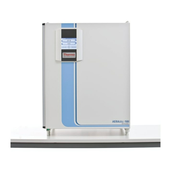
® Operating Instructions | HERAcell 150i / 240i Description of the device ® 4.1 Front view of HERAcell 150i [1] Stacking elements Front view [2] Plug caps [3] Glass door [4] Measuring cell with blower wheel and sensors [5] Door switch [6] Oxygen sensor (optional) [7] Pressure compensation opening with insert [8] Measuring opening... -
Page 27: Fig. 4: Front View Heracell ® 150I
® Operating Instructions | HERAcell 150i / 240i Description of the device Description of the device Description of the device ® Fig. 4: Front view HERAcell 150i 50115191 A / 08.2009... -
Page 28: Rear View Heracell ® 150I
® Operating Instructions | HERAcell 150i / 240i Description of the device Description of the device 4.2 Rear view HERAcell ® 150i [1] Access port, Ø 42 mm Rear view [2] Pressure compensation opening [3] Control box with supply interface for combined gas connection (optional) CO and O without gas monitoring... -
Page 29: Fig. 5: Rear View Heracell ® 150I
® Operating Instructions | HERAcell 150i / 240i Description of the device Description of the device Description of the device ® Fig. 5: Rear view HERAcell 150i 50115191 A / 08.2009... - Page 30 ® Operating Instructions | HERAcell 150i / 240i Description of the device Description of the device ® HERAcell Looped-through gas supply for 150i: [1] Control box with supply interface for combined gas connection (optional) CO and O with gas monitoring (optional) [2] Distributor connection for looping through the CO gas supply for up to three additional devices (independent of device type)
-
Page 31: Fig. 6: Looped-Through Gas Supply Heracell ® 150I
® Operating Instructions | HERAcell 150i / 240i Description of the device Description of the device Description of the device Fig. 6: Looped-through gas supply ® HERAcell 150i 50115191 A / 08.2009... -
Page 32: Front View Heracell ® 240I
® Operating Instructions | HERAcell 150i / 240i Description of the device Description of the device 4.3 Front view HERAcell ® 240i [1] Stacking elements Front view [2] Plug caps [3] Glass door [4] Measuring cell with blower wheel and sensors [5] Door switch [6] Oxygen sensor (optional) [7] Receptacle for bottle turning device (optional) -
Page 33: Fig. 7: Front View Heracell ® 240I
® Operating Instructions | HERAcell 150i / 240i Description of the device Description of the device Description of the device ® Fig. 7: Front view HERAcell 240i 50115191 A / 08.2009... -
Page 34: Rear View Heracell ® 240I
® Operating Instructions | HERAcell 150i / 240i Description of the device Description of the device 4.4 Rear view HERAcell ® 240i [1] Pressure compensation opening Rear view [2] Access port, Ø 42 mm [3] Condensate drain gutter [4] Control box with supply interface for combined gas connection (optional) CO and O without gas monitoring... -
Page 35: Fig. 8: Rear View Heracell ® 240I
® Operating Instructions | HERAcell 150i / 240i Description of the device Description of the device Description of the device Fig. 8: Rear view HERAcell ® 240i 50115191 A / 08.2009... - Page 36 ® Operating Instructions | HERAcell 150i / 240i Description of the device Description of the device ® Looped-through gas supply for HERAcell 240i: [1] Control box with supply interface for combined gas connection (optional) CO and O with gas monitoring (optional) [2] Distributor connection for looping through the CO gas supply for up to three additional devices (independent of device type)
-
Page 37: Fig. 9: Looped-Through Gas Supply Heracell ® 240I
® Operating Instructions | HERAcell 150i / 240i Description of the device Description of the device Description of the device Fig. 9: Looped-through gas supply ® HERAcell 240i 50115191 A / 08.2009... -
Page 38: Safety Devices
® Operating Instructions | HERAcell 150i / 240i Description of the device Description of the device 4.5 Safety devices The device is equipped with the following safety devices: • A door switch interrupts the CO supply and the work space heating when the glass door is opened. - Page 39 ® Operating Instructions | HERAcell 150i / 240i Description of the device Description of the device Termination of warranty! Using chlorinated tap water or additives that contain chlorine will void the manufacture warranty. Similarly, the use of ultrapure water whose conductivity is out of the range of 1 to 20 μS (and whose resistivity is out of the range of 50 kΩ...
-
Page 40: Door Switch
® Operating Instructions | HERAcell 150i / 240i Description of the device Description of the device Description of the device 4.7 Door switch A door switch [1] is installed at the upper edge of the work space opening. If the door switch is activated by opening the glass door, the gas supply and the heating of the work space are interrupted and the display shows a corresponding message. -
Page 41: Sensor System
® Operating Instructions | HERAcell 150i / 240i Description of the device Description of the device Description of the device 4.8 Sensor system The blower wheel and two sensor modules are integral to the baseplate [1] of the measuring cell: •... -
Page 42: Supply Interface
® Operating Instructions | HERAcell 150i / 240i Description of the device Description of the device Description of the device 4.9 Supply interface All supply connections are installed in the supply interface (control box [1]) in the rear of the device. Gas connection: The gas supply lines between the device and the gas supply system are connected using the supplied... - Page 43 ® Operating Instructions | HERAcell 150i / 240i Description of the device Description of the device Alarm contact: Fig. 12: The device can be connected to an on-site, external alarm system External alarm system (e.g. telephone system, building monitoring system, visual or audible alarm system).
-
Page 44: Work Space Components
® Operating Instructions | HERAcell 150i / 240i Description of the device Description of the device Description of the device 4.10 Work space components The work space of the incubator has only a minimum of surface, thereby supporting both the prevention of contamination and easy, effective decontamination. -
Page 45: Water Reservoir
® Operating Instructions | HERAcell 150i / 240i Description of the device Description of the device Description of the device of the openings are smaller when samples are accessed. 4.10.3 Water reservoir The water reservoir [1] is integral to the interior container floor and inclines toward the rear. -
Page 46: Rear Panel Openings
® Operating Instructions | HERAcell 150i / 240i Description of the device Description of the device Description of the device 4.10.6 Rear panel openings A pressure compensation opening with insert in the rear panel of the device allows a compensation between the pressures in the work space and in the operating room. -
Page 47: Shelf System
® Operating Instructions | HERAcell 150i / 240i Description of the device Description of the device Description of the device 4.10.7 Shelf system Fig. 16: The support rails [1] of the shelf system are perforated every 42 mm so that the support hooks [8] can be inserted variably for any culture container size required. -
Page 48: Water Pump
® Operating Instructions | HERAcell 150i / 240i Description of the device Description of the device Description of the device Receptacles: To prevent corrosion due to moisture in the work space, unassigned receptacles of the bottle turning device must always be plugged with the protective cap. -
Page 49: Start-Up
® Operating Instructions | HERAcell 150i / 240i Start-up 5.1 Preparing the work space 7. Upon delivery, the CO incubator is not in a sterile state. Before the initial start-up, the device must be decontaminated. Before the decontamination is performed, the following work space components must be cleaned: •... -
Page 50: Installing The Shelf Supports
® Operating Instructions | HERAcell 150i / 240i Start-up Start-up Start-up 5.2.2 Installing the shelf supports: 1. Fig. 19: Insert the shelf supports [3] into the perforations [1] of the support rail with the bar facing down. 2. Make sure that the two vertical elements [2] of the shelf support are flush with the support rail. -
Page 51: Installing The Optional Bottle Turning Devices Heracell 240I
® Operating Instructions | HERAcell 150i / 240i Start-up Start-up Start-up 5.4 Installing the optional bottle turning ® devices HERAcell 240i 1. Align the roller insert so that the roller holder [8] and the crossmember [7] are flush and facing the work space opening. - Page 52 ® Operating Instructions | HERAcell 150i / 240i Start-up Start-up Example: – Bottle diameter: 56 mm – Desired speed: 3.5 rpm – Determined set value: 48% In the dialog box S , the value 48% is set (see chap. PEED BOTTLE TURN DEVICE 7.11.3‚...
-
Page 53: Fig. 22: Bottle Turning Speed
® Operating Instructions | HERAcell 150i / 240i Start-up Start-up Start-up Fig. 22: Bottle turning speed 50115191 A / 08.2009... -
Page 54: Installing The Optional Center Strut Heracell ® 240I For Split Inserts
® Operating Instructions | HERAcell 150i / 240i Start-up Start-up Start-up 5.5 Installing the optional center strut ® HERAcell 240i for split inserts ® If HERAcell 240i is equipped with the optional 6- segment insert, two center struts [1] with perforations at each side must be installed. -
Page 55: Gas Connection
® Operating Instructions | HERAcell 150i / 240i Start-up Start-up Start-up 5.6 Gas connection Gas quality: The gases must have one of the following qualities: • Purity 99.5 % min, • medical gas quality. Overpressure! The operating pressure of the gas applied to the device must not exceed 1 bar. -
Page 56: Installing Devices Without The Optional Gas Monitoring System
® Operating Instructions | HERAcell 150i / 240i Start-up Start-up Start-up pressure compensation opening must not be extended or redirected. 5.6.2 Installing devices without the optional gas monitoring system The gas supply from the gas supply system to the device is established using the supplied flexible gas pressure hoses (see chap. -
Page 57: Combined Co Connection With Gas Monitoring System (Optional)
® Operating Instructions | HERAcell 150i / 240i Start-up Start-up Start-up 5.6.3 CO connection with gas monitoring system (optional) The gas supply from the gas supply system to the device is established by the supplied flexible gas pressure hoses. Fig. 26: Devices with CO connections that are equipped with the optional gas monitoring system are connected according to the connection diagram [7]. -
Page 58: Fig. 27: Combined Connection With Gas Monitoring System (Optional)
® Operating Instructions | HERAcell 150i / 240i Start-up Start-up Start-up connection of the gas monitoring system, • connect the gas container A [3] to the lower connection of the gas monitoring system, • The outlet of the gas monitoring system [4] is connected at the factory to the gas inlet filter [9] by a short gas pressure hose [11]. -
Page 59: Power Supply Connection
® Operating Instructions | HERAcell 150i / 240i Start-up Start-up Start-up 5.7 Power supply connection Electric shock! Contact with current-carrying components may cause a lethal electric shock. Before connecting the device to the power supply, check plug and power supply cable for damage. -
Page 60: Connecting The Rs 232 Interface
® Operating Instructions | HERAcell 150i / 240i Start-up Start-up 5.8 Connecting the RS 232 interface The RS 232 data communication interface has been designed for a cable Data communication via RS 232 connection with 9-pin connector and a contact assignment of 1:1. Data exchange is accomplished by a predefined structure of command sequences (see annex at the end of this section). -
Page 61: Connecting The Alarm Contact
Start-up Start-up 5.10 Connecting the alarm contact Skilled work: Thermo Scientific warrants the operational safety and the operativeness of the device only if installation and repairs are performed properly. The connection of the device to an external alarm system must... -
Page 62: Fig. 29: Connection Example
® Operating Instructions | HERAcell 150i / 240i Start-up Start-up Start-up Connection example: The connector [5] for the connecting cable is included in the standard equipment. The values for the operating voltage of the external circuits and of the fusing of the alarm system are given in the table on the previous page. -
Page 63: Operation
® Operating Instructions | HERAcell 150i / 240i Operation 6.1 Preparing the device The device must only be released for operation after all major measures for the start-up have been taken (see Section 5, page 45). Device check: Prior to starting operation, the following device components must be Device check checked for their correct function •... -
Page 64: Starting Operation
® Operating Instructions | HERAcell 150i / 240i Operation Operation 6.2 Starting operation 1. Fill the water tray with a sufficient quantity of processed water. Do not exceed the upper level mark. 2. Make sure that the CO supply system valves are open. 3. -
Page 65: Handling And Control (Ican™ Touchscreen Controller)
® Operating Instructions | HERAcell 150i / 240i Handling and control (iCan™ touchscreen controller) 7.1 Power switch Fig. 30: Depending on which side the door hinges are installed, the power switch [1] is integral to the front cover [2] of one of the front device stands. •... -
Page 66: Fig. 32: Ican™ Touchscreen Withouto 2 /N 2 Gas Supply
® Operating Instructions | HERAcell 150i / 240i Handling and control (iCan™ touchscreen controller) Handling and control (iCan™ touchscreen controller) Handling and control (iCan™ touchscreen controller) Versions without O control: Fig. 32: Function keys and value displays of the operating panel for a device version without O supply: [1] Type designation of the device [2] Temperature display... -
Page 67: Fig. 34: Menu Structure Overview
® Operating Instructions | HERAcell 150i / 240i Handling and control (iCan™ touchscreen controller) Handling and control (iCan™ touchscreen controller) Handling and control (iCan™ touchscreen controller) Fig. 34: Menu structure overview 50115191 A / 08.2009... -
Page 68: Factory Presettings Of The Ican™ Touchscreen Controls
® Operating Instructions | HERAcell 150i / 240i Handling and control (iCan™ touchscreen controller) Handling and control (iCan™ touchscreen controller) Handling and control (iCan™ touchscreen controller) 7.3 Factory presettings of the iCan™ touchscreen controls Upon delivery of the device, the following set values have been preset: •... -
Page 69: Event Actions For Settings
® Operating Instructions | HERAcell 150i / 240i Handling and control (iCan™ touchscreen controller) Handling and control (iCan™ touchscreen controller) Exposure to CO gas: During the 5-minute heat-up phase of the O control loop, the work space is not exposed to CO gas and the CO control and is disabled. -
Page 70: Setting The Temperature Set Value
® Operating Instructions | HERAcell 150i / 240i Handling and control (iCan™ touchscreen controller) Handling and control (iCan™ touchscreen controller) Handling and control (iCan™ touchscreen controller) 7.6 Setting the temperature set value 1. Press the T key [1]. EMPERATURE DISPLAY >... -
Page 71: Setting The Co Set Value
® Operating Instructions | HERAcell 150i / 240i Handling and control (iCan™ touchscreen controller) Handling and control (iCan™ touchscreen controller) Handling and control (iCan™ touchscreen controller) 7.7 Setting the CO set value 1. Press the CO key [1]. 2 DISPLAY >... -
Page 72: Setting The O Set Value
® Operating Instructions | HERAcell 150i / 240i Handling and control (iCan™ touchscreen controller) Handling and control (iCan™ touchscreen controller) Handling and control (iCan™ touchscreen controller) 7.8 Setting the O set value This setting is possible only on versions with the optional O control. -
Page 73: Auto-Start Routine
® Operating Instructions | HERAcell 150i / 240i Handling and control (iCan™ touchscreen controller) Handling and control (iCan™ touchscreen controller) 7.9 Auto-start routine The auto-start function is an automated routine for the start and the subsequent adjustment of the CO measuring system. - Page 74 ® Operating Instructions | HERAcell 150i / 240i Handling and control (iCan™ touchscreen controller) Handling and control (iCan™ touchscreen controller) • set value not plausible, • calibration values too high or too low, • sensor communication failure, • sensor parameter not plausible, •...
-
Page 75: Activating Auto-Start
® Operating Instructions | HERAcell 150i / 240i Handling and control (iCan™ touchscreen controller) Handling and control (iCan™ touchscreen controller) Handling and control (iCan™ touchscreen controller) 7.9.1 Activating auto-start Preparations for the start: 1. Make sure that the CO gas supply system valves are open. -
Page 76: Interrupting The Auto-Start Routine
® Operating Instructions | HERAcell 150i / 240i Handling and control (iCan™ touchscreen controller) Handling and control (iCan™ touchscreen controller) Handling and control (iCan™ touchscreen controller) • the outer door is opened on a device with optional gas-tight screen, • the power supply is interrupted. 7.9.2 Interrupting the auto-start routine If the S key in the status display is depressed (see... -
Page 77: Settings
® Operating Instructions | HERAcell 150i / 240i Handling and control (iCan™ touchscreen controller) Handling and control (iCan™ touchscreen controller) Handling and control (iCan™ touchscreen controller) • Keypad lock, • Software versions. To make a user-specific setting in a dialog box, navigate through the submenus listed in the illustrations and open the dialog box. -
Page 78: Fig. 42: Date / Time Setting
® Operating Instructions | HERAcell 150i / 240i Handling and control (iCan™ touchscreen controller) Handling and control (iCan™ touchscreen controller) Handling and control (iCan™ touchscreen controller) Fig. 41: To set the cursor to the left to overwrite a value: 5. Press the B key (<<) [6]. -
Page 79: Fig. 43: Display Contrast Setting
® Operating Instructions | HERAcell 150i / 240i Handling and control (iCan™ touchscreen controller) Handling and control (iCan™ touchscreen controller) Handling and control (iCan™ touchscreen controller) Setting the contrast: The input dialog allows the color contrast of the operating panel to be set within the value range of 48% to 80%. -
Page 80: Fig. 45: Rs 232 Interface Baud Rate Setting
® Operating Instructions | HERAcell 150i / 240i Handling and control (iCan™ touchscreen controller) Handling and control (iCan™ touchscreen controller) Handling and control (iCan™ touchscreen controller) Setting the interface baud rate: The input dialog allows the setting of the stepping rate for data communication of the: •... -
Page 81: Fig. 47: Language Setting
® Operating Instructions | HERAcell 150i / 240i Handling and control (iCan™ touchscreen controller) Handling and control (iCan™ touchscreen controller) Handling and control (iCan™ touchscreen controller) Setting the user display screen language: The input dialog allows the language of the display screen to be set. -
Page 82: Fig. 48: Reminder Interval Setting
® Operating Instructions | HERAcell 150i / 240i Handling and control (iCan™ touchscreen controller) Handling and control (iCan™ touchscreen controller) Handling and control (iCan™ touchscreen controller) Setting the reminder intervals: The reminder intervals are integral components of the alarm and monitoring system of the device control. For the two essential functions contra-con and auto- start as well as for routine service work, the user can set dates that trigger an alarm whenever they occur. -
Page 83: Event Logging
® Operating Instructions | HERAcell 150i / 240i Handling and control (iCan™ touchscreen controller) Handling and control (iCan™ touchscreen controller) Handling and control (iCan™ touchscreen controller) 7.11.2 Event logging The input dialogs of the category EVENT LOGGING comprise all settings for logging and outputting events during the operation of the device: •... -
Page 84: Fig. 51: Error Table Display
® Operating Instructions | HERAcell 150i / 240i Handling and control (iCan™ touchscreen controller) Handling and control (iCan™ touchscreen controller) Handling and control (iCan™ touchscreen controller) Fig. 50: The settings can be made within the value range of 10 seconds to 3600 seconds. 1. -
Page 85: Options
® Operating Instructions | HERAcell 150i / 240i Handling and control (iCan™ touchscreen controller) Handling and control (iCan™ touchscreen controller) Handling and control (iCan™ touchscreen controller) Troubleshooting: For a detailed overview of causes for errors and their correction, please refer to the end of this chapter! 7.11.3 Options The input dialogs of the O... -
Page 86: Fig. 53: Low Humidity Setting
® Operating Instructions | HERAcell 150i / 240i Handling and control (iCan™ touchscreen controller) Handling and control (iCan™ touchscreen controller) Handling and control (iCan™ touchscreen controller) Setting low humidity: If condensation occurs on the culture containers due to high relative humidity, the humidity in the work space can be set to a lower level. -
Page 87: Fig. 54: Gas Tight Screen Setting
® Operating Instructions | HERAcell 150i / 240i Handling and control (iCan™ touchscreen controller) Handling and control (iCan™ touchscreen controller) Handling and control (iCan™ touchscreen controller) Setting the gas-tight screen: As the aperture cross-sections are smaller when accessing the samples, devices equipped with the optional gas-tight screen achieve shorter recovery times for the incubation parameters: •... -
Page 88: Fig. 56: Alarm Relay Setting
® Operating Instructions | HERAcell 150i / 240i Handling and control (iCan™ touchscreen controller) Handling and control (iCan™ touchscreen controller) Handling and control (iCan™ touchscreen controller) > Press the E key [3]. NTER > The system returns to the Options menu. Switching the audible alarm on/off: If the device-integral monitoring system detects an error:... -
Page 89: Fig. 58: Switching The O 2 Control On And Off
® Operating Instructions | HERAcell 150i / 240i Handling and control (iCan™ touchscreen controller) Handling and control (iCan™ touchscreen controller) Handling and control (iCan™ touchscreen controller) Quick access to bottle turning device levels: To directly access the Bottle turning device submenu, touch the Bottle turning device icon in the main menu. -
Page 90: Icon Description
® Operating Instructions | HERAcell 150i / 240i Handling and control (iCan™ touchscreen controller) Handling and control (iCan™ touchscreen controller) Handling and control (iCan™ touchscreen controller) Gas monitoring: The switching state of the O control loop does not affect the function of the optional gas monitoring system. -
Page 91: Fig. 60: Gas Monitoring Icons
® Operating Instructions | HERAcell 150i / 240i Handling and control (iCan™ touchscreen controller) Handling and control (iCan™ touchscreen controller) Handling and control (iCan™ touchscreen controller) Gas cylinder empty: Error message, indicating, that the filling level of one or of serveral gas cylinders is too low to ensure regular gas supply. -
Page 92: Enabling/Disabling The Keypad Lock
® Operating Instructions | HERAcell 150i / 240i Handling and control (iCan™ touchscreen controller) Handling and control (iCan™ touchscreen controller) Handling and control (iCan™ touchscreen controller) Cylinder changeover: A manual or automatic changeover of a gas cylinder is entered into the event display. 7.11.5 Enabling/disabling the keypad lock This input dialog box allows the keypad lock to be enabled or disabled. -
Page 93: Software Versions
® Operating Instructions | HERAcell 150i / 240i Handling and control (iCan™ touchscreen controller) Handling and control (iCan™ touchscreen controller) Handling and control (iCan™ touchscreen controller) 7.11.6 Software versions This menu shows the unit software versions in the display [1]. •... -
Page 94: Scaling The Trend Display
® Operating Instructions | HERAcell 150i / 240i Handling and control (iCan™ touchscreen controller) Handling and control (iCan™ touchscreen controller) Handling and control (iCan™ touchscreen controller) 7.12 Scaling the trend display The trend display of the three control loops: • Temperature, •... -
Page 95: Error Messages
® Operating Instructions | HERAcell 150i / 240i Handling and control (iCan™ touchscreen controller) Handling and control (iCan™ touchscreen controller) Handling and control (iCan™ touchscreen controller) 7.13 Error messages The error detection system is an integral element of the device-internal control system. It monitors the control loops and their sensors. - Page 96 ® Operating Instructions | HERAcell 150i / 240i Handling and control (iCan™ touchscreen controller) Handling and control (iCan™ touchscreen controller) Handling and control (iCan™ touchscreen controller) Error message overview: Control Error message Cause Repair Alarm relay Buzzer loop Device door open Doors open for more than 10 System Close device doors...
- Page 97 ® Operating Instructions | HERAcell 150i / 240i Handling and control (iCan™ touchscreen controller) Handling and control (iCan™ touchscreen controller) Handling and control (iCan™ touchscreen controller) Error message overview: Control Error message Cause Repair Alarm relay Buzzer loop LM75 sensor cannot not Tempe- Failure LM75 communicate with...
- Page 98 ® Operating Instructions | HERAcell 150i / 240i Handling and control (iCan™ touchscreen controller) Handling and control (iCan™ touchscreen controller) Handling and control (iCan™ touchscreen controller) Error message overview: Control Error message Cause Repair Alarm relay Buzzer loop Gas cylinder changeover Failure gas cylinder switch cannot commuicate Contact Service...
-
Page 99: Shut-Down
® Operating Instructions | HERAcell 150i / 240i Shut-down 8.1 Shutting the device down Contamination hazard! If the work space surfaces are contaminated, germs can be transferred to the environment of the device. In case of a shut-down, the device must be decontaminated! 1. -
Page 100: Cleaning And Disinfection
® Operating Instructions | HERAcell 150i / 240i Cleaning and disinfection 9.1 Cleaning Incompatible cleaners! Some device components are made of plastic. Solvents can dissolve plastics. Strong acids or caustic solutions can cause to become brittle of the plastic. For cleaning plastic components and surfaces, do not use solvents that contain hydrocarbons, solvents with an alcohol content of more than 10% or strong acids or caustic solutions. -
Page 101: Decontamimation Procedures
® Operating Instructions | HERAcell 150i / 240i Cleaning and disinfection Cleaning and disinfection 9.2 Decontamimation procedures The operator must prepare hygiene regulations for the decontamination of the device in accordance with the application of the device. The following disinfection procedures are compatible with the device: Disinfection procedure Wipe/spray disinfection: The wipe/spray disinfection is used as the standardized manual disinfection... - Page 102 ® Operating Instructions | HERAcell 150i / 240i Cleaning and disinfection Cleaning and disinfection Preparing the manual wipe/spray disinfection: Electric shock! Contact with current-carrying components may cause a lethal electric shock. Prior to cleaning and disinfection work, disconnect the device from the power supply! •...
- Page 103 ® Operating Instructions | HERAcell 150i / 240i Cleaning and disinfection Cleaning and disinfection of the measuring cell. The wheel and the cover can be autoclaved. Removing blower wheel and cover: Electric shock! Contact with current-carrying components may cause a lethal electric shock.
-
Page 104: Contra-Con Decontamination Routine
The effectiveness of the contra-con decontamination routine has been certified by independent institutes. Information on these tests is available from Thermo Scientific upon request. After the run has been completed, the device must be started up again using the auto-start routine. - Page 105 ® Operating Instructions | HERAcell 150i / 240i Cleaning and disinfection Cleaning and disinfection Optional bottle turning device: Before starting the contra-con decontamination routine, all rollers must be removed from the incubator. The electrical connection sockets must then be sealed with the protecting caps.
-
Page 106: Fig. 65: Decontamination Routine Phases
® Operating Instructions | HERAcell 150i / 240i Cleaning and disinfection Cleaning and disinfection Cleaning and disinfection Operating phases of contra-con decontamination: The remaining run time of the contra-con decontamination routine describes the time between the start or the current time status to the end of the drying phase. -
Page 107: Activating The Contra-Con Routine
® Operating Instructions | HERAcell 150i / 240i Cleaning and disinfection Cleaning and disinfection Cleaning and disinfection 9.4.1 Activating the contra-con routine Fig. 66: The contra-con decontamination routine is used to decontaminate the complete work space . 1. Press the key [1]. -
Page 108: Contra-Con Interruption Due To Error
® Operating Instructions | HERAcell 150i / 240i Cleaning and disinfection Cleaning and disinfection Cleaning and disinfection If the S key is pressed, the routine is interrupted and the contra-con Stop dialog box is opened as a security request. The routine can now be ultimately cancelled or resumed. -
Page 109: Completing Contra-Con
® Operating Instructions | HERAcell 150i / 240i Cleaning and disinfection Cleaning and disinfection Cleaning and disinfection 9.4.4 Completing contra-con After the five phases have been completed, the Stop dialog box [1] CONTRA CON DECONTAMINATION ROUTINE is displayed. The decontamination routine must be stopped manually. -
Page 110: Maintenance
® Operating Instructions | HERAcell 150i / 240i Maintenance 10.1 Inspections and checks To ensure the operativeness and the operational safety of the device, the functions and device components listed below must be checked at different intervals. Daily check: • Gas supply of the CO supply system. -
Page 111: Preparing The Temperature Calibration
® Operating Instructions | HERAcell 150i / 240i Maintenance Maintenance Maintenance 10.3 Preparing the temperature calibration To determine the exact measured value of the device- integral temperature sensor, a temperature comparison measurement has to be performed every three months. If a major temperature deviation is found during this check, a temperature calibration is required. -
Page 112: Temperature Calibration Procedure
® Operating Instructions | HERAcell 150i / 240i Maintenance Maintenance Maintenance 4. Close the doors. 5. Wait until the temperature value displayed on the measuring instrument has stabilized. 6. Calibrate the temperature control as described in (see chap. 10.4‚ pg. 112) 10.4 Temperature calibration procedure Measurement example: •... -
Page 113: Preparing The Co Calibration
® Operating Instructions | HERAcell 150i / 240i Maintenance Maintenance Maintenance Value reset: If the value isn’t changed within the next 30 seconds, the system automatically exits the menu, and the most recently confirmed value is preserved. 10.5 Preparing the CO calibration To determine the exact measured value of the device- integral CO... -
Page 114: Fig. 72: Gas-Tight Screen Measurement Opening
® Operating Instructions | HERAcell 150i / 240i Maintenance Maintenance Maintenance 4. For devices equipped with the optional gas-tight screen, the measurement opening is located: ® – on HERAcell 150 i [1] in the center gas-tight screen, ® – on HERAcell 240 i [2] in the left center gas- tight screen. -
Page 115: Co Calibration Procedure
® Operating Instructions | HERAcell 150i / 240i Maintenance Maintenance Maintenance 10.6 CO calibration procedure Measurement example: • CO set value: 5 % Reference temperature: 5,6 % 1. Press the CO key [1]. ISPLAY > The CO menu is displayed. 2. -
Page 116: Replacing The Gas Inlet Filter
® Operating Instructions | HERAcell 150i / 240i Maintenance Maintenance Maintenance 10.7 Replacing the gas inlet filter Fig. 74: The gas inlet filter (CO supply) has plastic threads and is screwed by hand into the threaded hole at the control box. Procedure for gas supply gas inlet filter: 1. -
Page 117: Replacing The Door Seal
® Operating Instructions | HERAcell 150i / 240i Maintenance Maintenance Maintenance 10.9 Replacing the door seal The door seal (magnetic seal) [3] of the outer door is located in the retaining slot. No tools are required to replace the seal. 1. -
Page 118: Disposal
® Operating Instructions | HERAcell 150i / 240i Disposal Contamination hazard! The device may have been used for treating and processing infectious substances. Therefore, the device and device components may have been contaminated. Prior to disposal, all device components must be decontaminated. - Page 119 ® Operating Instructions | HERAcell 150i / 240i Disposal Disposal Disposal Overview of the materials used: Component Material Thermal insulation components Polystyrene foam EPS/PPS-Compound Enclosed electrical components coated with different Printed circuit boards plastics, equipped on epoxy resin-bound boards. Plastic components, general Note material labelling Exterior housing Galvanized steel sheet, painted...
-
Page 120: Technical Data
® Operating Instructions | HERAcell 150i / 240i Technical data ® HERAcell 150i Description Unit Value Mechanical External dimensions (W x H x T) 637 x 867 x 782 Interior dimensions (W x H x T) 470 x 607 x 530 Chamber volume approx 151 Shelves (W x T) - Page 121 ® Operating Instructions | HERAcell 150i / 240i Technical data Technical data Technical data ® HERAcell 150i Description Unit Value gas supply system Gas purity min. 99.5 or medical quality Prepressure min. 0.8 - max. 1 Measuring and control range % vol.
- Page 122 ® Operating Instructions | HERAcell 150i / 240i Technical data Technical data Technical data ® HERAcell 240i Description Unit Value Mechanical External dimensions (W x H x T) 780 x 934 x 834 Interior dimensions (W x H x T) 607 x 670 x 583 Chamber volume approx 238...
- Page 123 ® Operating Instructions | HERAcell 150i / 240i Technical data Technical data Technical data ® HERAcell 240i Description Unit Value gas supply system Gas purity min. 99.5 or medical quality Prepressure min. 0.8 - max. 1 Measuring and control range % vol.
-
Page 124: Annex: Data Communication
® Operating Instructions | HERAcell 150i / 240i Annex: Data communication 13.1 Interfaces 13.1.1 RS 232 interface The RS 232 data communication interface has been designed for a cable RS 232 configuration connection with 9-pin connector and a contact assignment of 1:1. Setting the transmission speed: •... -
Page 125: Installing The Usb Port Driver
® Operating Instructions | HERAcell 150i / 240i Annex: Data communication Annex: Data communication 13.1.3 Installing the USB port driver ® Connect the USB cable (optional) to the control box of the HERAcell 150 i / 240 i and to a PC. As soon as the Windows Hardware Detector has identified the USB port, the F dialog box opens. - Page 126 ® Operating Instructions | HERAcell 150i / 240i Annex: Data communication Annex: Data communication 2. Select the data CD as source. 3. On the data CD, select the D sub-directory. RIVER 4. The installation routine installs the driver: EVAL22 Board USB. After the installation has been completed successfully, the routine is completed with F INISH...
-
Page 127: Structure Of The Command Sequences For Data Communication
® Operating Instructions | HERAcell 150i / 240i Annex: Data communication Annex: Data communication 13.2 Structure of the command sequences for data communication All characters sent and received in the data exchange between a PC and the ® incubator HERAcell 150 i / 240 i are ASCII characters that can be displayed on a conventional terminal. -
Page 128: Overview Of General Parameters (Addresses 0Xxx)
® Operating Instructions | HERAcell 150i / 240i Annex: Data communication Annex: Data communication checksum and <CR> XX = 2 bytes error message (see table below) Example of an unknown command: Query: ?:0005:00::cc<CR> Response !:0005:02:?1:cc<CR> Significance of the two bytes in the error mesage: Error message Description Error in telegram structure or checksum... -
Page 129: Overview Of Incubator Parameters (Addresses 2Xxx)
® Operating Instructions | HERAcell 150i / 240i Annex: Data communication Annex: Data communication 13.4 Overview of incubator parameters (addresses 2xxx) Incubator parameters are divided into: Incubator parameters • the basic parameters of the three control loops temperature, CO , and •... -
Page 130: Reading Internal Function Parameters
® Operating Instructions | HERAcell 150i / 240i Annex: Data communication Annex: Data communication 13.4.2 Reading internal function parameters Reading internal functions Address Description Note Status of run*1) and remaining 25 bytes / decimal value in run time [hours:minutes] for 2100 format disinfection, also date and time... - Page 131 ® Operating Instructions | HERAcell 150i / 240i Annex: Data communication Annex: Data communication Note on *3) disinfection and autostart run status: Disinfection auto-start 0x00 contra-con not active auto-start not active 0x01 Initialization Initialization 0x02 Await door opening time Await door opening time 0x03 Await door closing Await door closing...
-
Page 132: Error Memory Structure
® Operating Instructions | HERAcell 150i / 240i Annex: Data communication Annex: Data communication 13.5 Error memory structure The error memory contains 22 error messages. A query is responded with 11 data sets with a colon as separator and can be queried using the following command: Query: ?:2300:00::cc<CR>... -
Page 133: Error Memory Data Set Structure Scheme
® Operating Instructions | HERAcell 150i / 240i Annex: Data communication Annex: Data communication 13.5.1 Error memory data set structure scheme: 0b 01 8000 0002 Faulty control loop type 0x00 = Error in temperature control loop Date / Day 0x0b = 11th day of the month Date / Month 0x01 = January Date / Year... -
Page 134: Overview Of The Possible Error Messages In Bit Coding
® Operating Instructions | HERAcell 150i / 240i Annex: Data communication Annex: Data communication 13.5.3 Overview of the possible error messages in bit coding General device status, control loop for temperature and CO Bit-coded error messages for temperature and CO General device status 0x0002 Device door open too long... - Page 135 ® Operating Instructions | HERAcell 150i / 240i Annex: Data communication Annex: Data communication Control loop for O and water level: Bit-coded error messages for and water level control loop error status 0x0001 Sensor breakage 0x0002 Value above set value upper limit 0x0004 Value below set value lower limit 0x0020...
-
Page 136: Data Logger Structure
® Operating Instructions | HERAcell 150i / 240i Annex: Data communication Annex: Data communication 13.6 Data logger structure The data logger can store up to 10,000 events. Depending on the setting for the logging cycle (in sections of seconds), e.g. for a value of 60 s (default value), the events of about 5 days can be stored. -
Page 137: Data Logger Data Set Structure Scheme
® Operating Instructions | HERAcell 150i / 240i Annex: Data communication Annex: Data communication 13.6.1 Data logger data set structure scheme: 01 0b 01 06 0f 37 0000 0177 0028 00d4 0000 Data logger entry type 0x01 = Standard entry that is stored every 60 s Date / Day... -
Page 138: Overview Of Possible Event Entries In Bit Coding
® Operating Instructions | HERAcell 150i / 240i Annex: Data communication Annex: Data communication 13.6.2 Overview of possible event entries in bit coding Overview of event entries, Part I: Bit-coded event entries Code Event Special information (byte 8-15) Set values from all control Current values for temperature, 0x01 loops (periodically in minute... - Page 139 ® Operating Instructions | HERAcell 150i / 240i Annex: Data communication Annex: Data communication Overview of event entries, Part II: Bit-coded event entries Code Event Special information (byte 8-15) Status / error registration for 0x52 auto-start completed with error temperature, CO , and rh Status / error registration for 0x53...
-
Page 140: Examples Of Data Logger Codes
® Operating Instructions | HERAcell 150i / 240i Annex: Data communication Annex: Data communication 13.7 Examples of data logger codes An entry in the data logger is 16 bytes large and has the following structure: Data logger entry 1. byte: indicates the event (e.g. door open 0x31, measured value entry 0x01) 2. - Page 141 ® Operating Instructions | HERAcell 150i / 240i Annex: Data communication Annex: Data communication // calculate checksum: inverted XOR of all bytes // without checksum and <CR> for (i = 0; i < 11; i ++) bcc = (bcc^string[i]); // copy checksum string[11] = hexa(bcc/16);...
- Page 142 ® Operating Instructions | HERAcell 150i / 240i Annex: Data communication Annex: Data communication // cut off decimal place z = z / 10; // calculate and copy number before decimal separator for (i = 0; i < 12; i++){ // calculate value a[i] = z%10+0x30;...
- Page 143 ® Operating Instructions | HERAcell 150i / 240i Annex: Data communication Annex: Data communication // length of sent payload len = (ahex(buffer[7]) * 0x10 + ahex(buffer[8])) / 2; // converting ASCII string into usable numeric string for (i = 0; i < (len); i++) zahlenstring [i] = (ahex(buffer[10 + (2*i)]) * 0x10 + ahex(buffer[11 + (2*i)]));...
- Page 144 ® Operating Instructions | HERAcell 150i / 240i Annex: Data communication Annex: Data communication else{ str_cpy (&excelstring[len], "ok;", 3); len += 3; // copy nominal values from numerical string to Excel string len += num_2_str ((zahlenstring[8+i*SIZE_DATA2]*0x100+ zahlenstring[9+i*SIZE_DATA2]), &excelstring[len]); excelstring[len ++] = ';'; len += num_2_str ((zahlenstring[10+i*SIZE_DATA2]*0x100+ zahlenstring[11+i*SIZE_DATA2]), &excelstring[len]);...
-
Page 145: Program Heracell 150I & 240I
150i / 240i Annex: Data communication Annex: Data communication 13.8 Program Heracell 150i & 240i The program provides a user surface (only with English menu designation) User surface for data communication for handling the data communication between a device and a connected This program is used for: •... -
Page 146: Installing The Heracell 150I & 240I
Operating Instructions | HERAcell 150i / 240i Annex: Data communication Annex: Data communication 13.8.1 Installing the Heracell 150i & 240i 1. Starting the installation routine: Installation routine > On the data CD in the subdirectory P , double-click on the... -
Page 147: Operating The Heracell 150I & 240I
Operating Instructions | HERAcell 150i / 240i Annex: Data communication Annex: Data communication 13.8.2 Operating the Heracell 150i & 240i User menu structure: The user surface is divided into two main menus: • MAIN with two functional elements: – Program version output F IRMWARE VERSION –... - Page 148 ® Operating Instructions | HERAcell 150i / 240i Annex: Data communication Annex: Data communication Function of the user menu: PRESETTING The submenu PRESETTING is used to set the transmission speed and to Presetting select the serial port. 1. Select a transmission speed within the range of 9,600 to 115,200 baud. 2.
- Page 149 ® Operating Instructions | HERAcell 150i / 240i Annex: Data communication Annex: Data communication TEST COM The submenu TEST COM is used for testing the communication Test Com connection with the settungs defined in the submenu PRESETTING. 1. Example of a query for the currently measurable temperature values of the incubator: >...
- Page 150 ® Operating Instructions | HERAcell 150i / 240i Annex: Data communication Annex: Data communication DATE & TIME The submenu DATE & TIME is used for adjusting date and time to the Date & Time desired time zone. 1. Data in the two text boxes must be entered in the format DD.MM.YY (day, month, year).
- Page 151 ® Operating Instructions | HERAcell 150i / 240i Annex: Data communication Annex: Data communication • Saving data sets as files: > Press the S button. AVE TO FILE DATA LOGGER The submenu DATA LOGGER is used for reading the event entries into the Data Logger text box of the user surface.
- Page 152 ® Operating Instructions | HERAcell 150i / 240i Annex: Data communication Annex: Data communication SERVICEFILE The submenu SERVICEFILE is used for reading error informations and for Servicefile creating a service file from it, saved with the proprietary extension *srf. The service file is transmitted to the Technical Service of Thermo Fisher Scien- tific for fault analysis.
- Page 153 ® Operating Instructions | HERAcell 150i / 240i Annex: Data communication Annex: Data communication PASSWORD The submenu PASSWORD can only be accessed by the service personnel Password of Thermo Fisher Scientific. 50115191 A / 08.2009...
-
Page 154: Device Log
® Operating Instructions | HERAcell 150i / 240i Device log Please list carried out works here: Device type: Part number: Serial number: Service number: Location: Operator's note: Work carried out Notes Date Signature 50115191 A / 08.2009...
Need help?
Do you have a question about the HERAcell 150i and is the answer not in the manual?
Questions and answers