Table of Contents
Advertisement
Quick Links
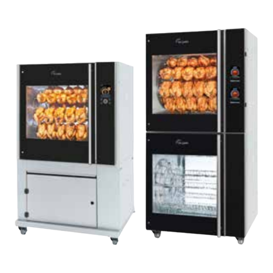
SERVICE MANUAL
MODELS
TDR7i auto clean
TDR7s auto clean
TDR7+7s auto clean
This manual is prepared for the use of trained Service Technicians and should not be used by
This manual is not intended to be all encompassing. If you have not attended a training for
Reproduction or other use of this Manual, without the express written consent of Fri-Jado, is
Service Manual TDRac
USA form 9120931 rev. 09/2022
PKII
TDR auto-clean
those not properly qualified. If you have attended a training for this product, you may be
qualified to perform all the procedures in this manual.
this product, you should read, in its entirety, the repair procedure you wish to perform to
determine if you have the necessary tools, instruments and skills required to perform the
procedure. Procedures for which you do not have the necessary tools, instruments and
skills should be performed by a trained technician.
TDR5s ac
- NOTICE -
prohibited.
TDR8i ac
TDR7i ac
TDR8+8s ac
TDR7+7s ac
Advertisement
Table of Contents
Troubleshooting

Subscribe to Our Youtube Channel
Related Manuals for Fri-Jado TDR7i auto clean


Summary of Contents for Fri-Jado TDR7i auto clean
- Page 1 Procedures for which you do not have the necessary tools, instruments and skills should be performed by a trained technician. Reproduction or other use of this Manual, without the express written consent of Fri-Jado, is prohibited. Service Manual TDRac USA form 9120931 rev.
- Page 2 Service Manual TDRac USA form 9120931 rev.09/2022 Page 2 PKII...
-
Page 3: Table Of Contents
Versions Version Issue date Remarks dd/mm/yy 1711 28/11/2017 First release 1803 07/03/2018 general update 1810 19/10/2018 Unpack instructions changed and minor changes in exploded views 1905 28/05/2019 Extended with TDR7+7 ac dimension drawing and electrical diagram + minor corrections in parts lists 2008 26-6-2020 Increased power connection. - Page 4 The Cleaning program .......................... 27 Cleaning the touch screen (while in operation) ..................27 Cleaning Process TDRac (3 cycles) ....................28 2 Pumps system and valves in action during cleaning................29 1 Pump system and valves in action during cleaning ................31 I/O test ..............................
- Page 5 TDRac, Rotor ............................90 TDRac, Partslist Rotor .......................... 91 TDR7ac, Blower & Heating from serial nr. 100105707 ................. 92 TDR7ac, Partslist Blower & Heating from serial nr. 100105707............93 TDRac, Blower & Heating ........................94 TDR7ac, Partslist Blower & Heating untill serial nr. 100099039 ............95 TDR7ac from 100099040 and TDR7+7ac, Blower &...
-
Page 6: Tdr-Ac Installation
TDR-AC INSTALLATION TDRAC, TECHNICAL DATA Consult the identification plate to get the proper specifications of the unit. The electrical data may vary from country to country. American models Models TDR 7-AC TDR 7+7-AC Dimensions approx. Width inch Depth inch 38½ 38½... - Page 7 TDR-ac Installation Service Manual TDRac USA form 9120931 rev. 09/2022 Page 7 PKII...
-
Page 8: Introduction
TDR-ac Installation INTRODUCTION • Unpacking of the unit. • Remove the pallet under the unit with the help of a fork lift. • Put the unit on his location. • Check if there is enough free space around the unit (see installation drawing). •... - Page 9 TDR-ac Installation Remove screws (front 4x and back 4x) Cut straps, remove box and tempex. Fasten the ramps ! Fasten the ramps ! Keep locked ! Keep locked ! Place the ramps in front of the pallet Tilt the unit slightly and remove the front beam. and fasten them.
-
Page 10: Location
TDR-ac Installation LOCATION The oven must be installed on a level surface. The installation location must allow adequate clearances for servicing and proper operation. The oven must be protected against falling moisture ! IMPORTANT: Make sure you lea- ve sufficient space around the ro- tisserie to easily remove or insert the rotor. -
Page 11: Legs / Castors
TDR-ac Installation LEGS / CASTORS The TDR ac is placed on a stand with 2 swivel and 2 locking swivel castors. TETHERING OF THE UNIT Warning: Safety standards require that, when this appliance is properly connected to the electrical power supply using flexible conduit, adequate means be provided to limit movement of the ap- pliance without depending on or transmitting stress to the electrical conduit. -
Page 12: Power, Water And Drain Connections Tdr7/8 Ac
TDR-ac Installation POWER, WATER AND DRAIN CONNECTIONS TDR7/8 AC The Power, water and drain connections can be found on the back of the unit. 200-230 V USA models Power connection NEMA 15-50 L= 1,9 mtr (75”) Water supply hose G 3/4”, L= 1,1 mtr (43”) Flush the tap before connecting Drain hose, Ø... -
Page 13: Water Requirements
TDR-ac Installation WATER REQUIREMENTS The supplied tap water must have the following conditions: 1. Minimum pressure 200 kPa (2 bar) 2. Maximum pressure 500 kPa (5 bar) 3. Maximum water temperature 40 °C (100 °F) 4. Acidity pH 7.0 - 8.0 5. -
Page 14: Connecting The Drain Tube
EXTRACTION OF THE ROTISSERIE An extraction hood is prescribed when the unit is NOT delivered with the special Fri-Jado Exhaust Hood mounted on it. The TDR8 produces about 10 m³ (350 cf) vapour during a cooking cycle. When placing the rotis- serie under an extraction hood, the following guide lines have to be considered: •... -
Page 15: Grease Collection
TDR-ac Installation GREASE COLLECTION TDR7/8-ac: Place the bucket, which is delivered with the unit, inside the stand under the drain pipe. It is also possible to put other containers in the underframe to collect the grease. Note 1: In one run, 5 liters (1.3 gallon) grease can come out. Note 2: The temperature of the grease can go up to 80 °C (176 °F). - Page 16 TDR-ac Installation >100 (4”) 1305 (51 3/8”) >50 (2”) Location of mains connection Location of water connectionG 3/4” BSP Location of drain hose OD Ø 33 mm (1 1/16”) Minimum required space 1 2 3 Example of funnel Sewer pipe ID ≥ Ø 40 mm (1 5/8”) >50 (2”) 820 (32 1/4”) >300 (12”)
- Page 17 TDR-ac Installation >50 (4”) 1415 (55 5/8”) >50 (2”) Location of mains connection Location of water connectionG 3/4” BSP Location of drain hose OD Ø 33 mm (1 1/16”) 557 (22”) Minimum required space 1 2 3 Example of funnel Sewer pipe ID ≥...
-
Page 18: Tdr 7/8 Ac On Stand
TDR-ac Installation TDR 7/8 AC ON STAND >100 (4”) 1615 (63 5/8”) >50 (2”) Location of mains connection Location of water connectionG 3/4” BSP Location of drain hose OD Ø 33 mm (1 1/16”) Minimum required space Example of funnel Sewer pipe ID ≥... -
Page 19: Tdr 7/8Ac With Hood
TDR-ac Installation TDR 7/8AC WITH HOOD >50 (2”) 1730 (68 1/8”) >50 (2”) Location of mains connection Location of water connectionG 3/4” BSP Location of drain hose OD Ø 33 mm (1 1/16”) Minimum required space Example of funnel 650 (25 5/8”) Sewer pipe ID ≥... -
Page 20: Tdr 7+7 Ac / 8+8 Ac
TDR-ac Installation TDR 7+7 AC / 8+8 AC >100 (4”) 1615 (63 5/8”) >50 (2”) Location of mains connection Location of water connectionG 3/4” BSP Location of drain hose OD Ø 33 mm (1 1/16”) Minimum required space Delivered water hose G3/4”, 1,5 mtr (5ft) Sewer pipe ID ≥... - Page 21 TDR-ac Installation A= Power connection B= Water connection 3/4” C= Grease drain D= Waste water drain hose pillar 3/4” Service Manual TDRac USA form 9120931 rev. 09/2022 Page 21 PKII...
-
Page 22: Tdr 7/8 Ac On Counter
TDR-ac Installation TDR 7/8 AC ON COUNTER Support Driptray Driptray Space for intake cooling air Footprint dimensions, seen from above A= Power connection B= Water connection 3/4” C= Grease drain D= Waste water drain hose pillar 3/4” Service Manual TDRac USA form 9120931 rev.09/2022 Page 22 PKII... -
Page 23: Software "S" Controller (Touch Screen)
SOFTWARE “S” CONTROLLER (TOUCH SCREEN) SWITCHING ON Main functions Other symbols Touch the screen somewhere Language Pause Home screen Extra time ON / OFF or stop program Continue Recipes menu Create recipe Home screen Edit recipe Touch the ON / Cleaning program OFF symbol Confirm... -
Page 24: Running A Cooking Program
RUNNING A COOKING PROGRAM Push recipes icon Choose program Check fat container and Start program push “continue” Change fat container Cancel Continu The below 4 steps are only applicable in case the cooking program has a pre-heat step. Preheat starts. Preheat done, open the Load products and close Push... -
Page 25: Creating A Cooking Program
CREATING A COOKING PROGRAM Chose product icon and fill in recipe name. Push recipes icon Push icon Chose or change step name if applicable. Drag up for an extra cooking step. Chicken Create Recipe My Recipe Other name if applicable Push time and temperature and adjust. -
Page 26: Example Of Error Message
EXAMPLE OF ERROR MESSAGE In the “log” menu the er- Select the error Example motor failure Meta data is shown during cooking. ror can be found Motor failure In manager menu: Go to the manager menu to clear the error. Scroll to “Clear errors”... -
Page 27: The Cleaning Program
THE CLEANING PROGRAM Push cleaning icon Choose program If unit is too hot, it will Now it is asked to place cool down first. the detergent. Follow the instructions that can be found in the container with detergent. Place the detergent. Push to pause, if appli- Cleaning program has... -
Page 28: Cleaning Process Tdrac (3 Cycles)
CLEANING PROCESS TDRAC (3 CYCLES) Descale – Full Descale Disabled / Full / Short Daily Clean Daily clean – Enabled / Disabled Quick clean – Enabled / Disabled Clean start Clean Cycles - 3 Clean temp 2 - 60 °C Soap safe temp - 75 °C Soap cooling Add cleaner... -
Page 29: Pumps System And Valves In Action During Cleaning
2 PUMPS SYSTEM AND VALVES IN ACTION DURING CLEANING Valve position during cooking cooking cooking The pictures below show each stage in the cleaning pro- gram. -Tubes in red, are flowing -Pump or valves in yellow are active / open. -Soap has to be added after stage 1 -The first cycle is following stage 1 untill 10. - Page 30 The stage 3 and 4 are rehearsing alternately, during 1 minute each, over a period of 40 minutes, with the heating on and after that, during 5 minutes with the heating off. The third cycle has only heating on. In case of a sanitation step, that will be like stage 10, but then only with the heating on. Rinse B left 10 sec Drain 180 sec rinse B left 10 sec...
-
Page 31: Pump System And Valves In Action During Cleaning
1 PUMP SYSTEM AND VALVES IN ACTION DURING CLEANING Valve position during cooking cooking cooking The pictures below show each stage in the cleaning pro- gram. -Tubes in red, are flowing -Pump or valves in yellow are active / open. -Soap has to be added after stage 1 -The first cycle is following stage 1 untill 10. - Page 32 The stage 3 and 4 are rehearsing alternately, during 1 minute each, over a period of 40 minutes, with the heating on and after that, during 5 minutes with the heating off. The third cycle has only heating on. In case of a sanitation step, that will be like stage 10, but then only with the heating on. Drain 180 sec Rinse B left 10 sec rinse B left 10 sec...
-
Page 33: I/O Test
I/O TEST Gain access to the service menu 4878 Select “I/O test” “Analog input” shows PT1000 temperature (in 0,1 degrees) Example below is 67°C, (which is 152°F), see table below “Digital inputs” is showing the available inputs and also which contacts are closed. -
Page 34: Exchanging Data With The Usb Drive
EXCHANGING DATA WITH THE USB DRIVE The password for service is 4878. Once the service menu is entered, also the manager menu is unlocked. Copies recipes from the controller to the USB drive Copies recipes from the USB drive to the con- troller. -
Page 35: Updating Software Tdrac (S-Control)
UPDATING SOFTWARE TDRAC (S-CONTROL) Preparing the software (firmware) 4. The following messages appear Bootloader version V4.03.04 The software comes in a .zip file. The name cor- -USB stick found responds with the version of the software. For starting upgrade example: V1_00_3.zip. -Copying update.tar 1. -
Page 36: Automatic Cook Correction
AUTOMATIC COOK CORRECTION The automatic cook correction facility will automaticly add or deduct time to the pro- grammed cooking time in order to have constant cooking quality. To activate it, the parameter “auto correct” has to be put on “time”. Go to the manager menu -->... -
Page 37: Default Parameters Version 1.00.38 Tdrs-Ac 230V Eur
DEFAULT PARAMETERS VERSION 1.00.38 TDRS-AC 230V EUR About / software version 1.00.34 Manager Change Pin code 0000 - 9999 Toggle Light on - off Temperature unit °F °C - °F Volume unit filter gallons liters-gallon UTC time Local time UTC date Actual date Time zone offset -12 / 12... - Page 38 demo clean start no-yes auto off time 60 min no or 10 - 240 change pin **** read out of the manager pin code Drain duration 40 sec. 10 -40 Fat drain auto open - auto Clean Cycles Clean temperature temp 1 48 °C 25 - 60...
- Page 39 Digital outputs read the inputs and set the outputs Board Feed- read the inputs and set the outputs back Board Version read the inputs and set the outputs Board Variant read the inputs and set the outputs Test program no -yes Ignore errors no - yes save HACCP...
- Page 40 Rotor Reset rotor time no - yes Light Reset light time no - yes Pump Reset Pump time no - yes Start/End Counters #started recipes #ended recipes #started quick clear #ended quick clean #started daily clean #ended daily clean #started full descale #ended full descale #started short descale #ended short descale...
-
Page 41: Explanation Of Parameters
EXPLANATION OF PARAMETERS Level 1 Level 2 Level 3 Change Pin code Option to change the manager pin code Toggle Light Option to switch on or off the interior light. Temperature unit Change the temperature units from Fahrenheit to Celcius or from Clecius to Fahrenheit. Volume unit filter Change the volulme units from Liters to Gallon or from Gallon to Liters. - Page 42 Level 1 Level 2 Level 3 Drain time Option to set the drain time when demo mode is activated Supply time 1 Option to set the (water) Supply time when demo mode is activated demo clean start Option to start a demo clean cycle auto off time Option to swith off the rotisserie automaticly after the set time when not operated.
- Page 43 Wifi Smartphone Optin to allow a connection to an Smartphone Wifi smart Cloud Option to enable a connection to the Fri-Jado Smart Connect website. Wifi RSSI Shows the signal level of the WiFi connection. Values are between -101dBm and -1dBm. In practice values are between -85dBm and -25dBm.
- Page 44 Level 1 Level 2 Level 3 Customer ID By entering the a maching customer code the correct story boards and explanations are given in the help function Restart soft This performs a 'soft' reboot of the entire S control software. This means that the entire soft- ware restarts internally without an external electrical reset signal being issued.
-
Page 45: Software "I" Controller
SOFTWARE “I” CONTROLLER MENU SETTINGS TDRAC To enter the set up of the TDR AC press the on/off key for 3 seconds. Selection buttons The main screen will show 3 options: • operate Display • program • settings Select the program by pushing the corresponding key. -
Page 46: Cleaning Program Tdrac
CLEANING PROGRAM TDRAC An overview of the various steps of the cleaning program. Go to: Settings->service. The amount of time of the various steps can be adjusted in minutes or seconds. Service Manual TDRac USA form 9120931 rev. 09/2022 Page 46 PKII... -
Page 47: Menu Settings Tdrac
MENU SETTINGS TDRAC Settings Information The Information screen will display the following information about the rotisserie: • Device type (TDRi) • Firmware version of the CPU board (version: 6.01.00) • Last error • Firmware version of the I/O board (MFMB:v1.00) Manager The manager settings are used to change local settings like tem- perature, date/time or to load recipes. -
Page 48: First Settings And Diagnostic Tools Tdr Ac
FIRST SETTINGS AND DIAGNOSTIC TOOLS TDR AC Miscellaneous service settings device type After replacing a cpu board the device type needs to be filled in. set language The next setting after replacing a board is to set language to local. Error history Read out Save on USB stick... -
Page 49: I/O Test Tdrac (I-Control)
I/O TEST TDRAC (I-CONTROL) Several I/O test can be executed: Go to settings -> service -> I/O test. All switched electrical parts can be tested via TEMB outputs. Go to: settings -> service -> I/O test -> TEMB outputs See next page for an overview of connectors and relays. Note that a led will illuminate if a relay is switched on. - Page 50 Device Relay Connec- 2 pumps system BROWN WHITE R1 -> J2-4 M1 Rotor J2-4 WHITE/A Rotor motor R3 -> J2-3 M2 Blower J2-3 P1 / P2 Blower Q3 / K4 R2 -> J2-1 K1 Heater J2-1 Heating Rd Ye Bu J8-2 J8-1 Q2 / ---...
-
Page 51: Updating Software Tdrac (I-Control)
UPDATING SOFTWARE TDRAC (I-CONTROL) Preparing the software (firmware) 3. Connect the mains supply The software comes in a .zip file. The name cor- responds with the version of the software. For example: V5_00_13.zip. After extracting 4. The following messages appear Bootloader version V1.02.02 -USB stick found 1. - Page 52 Service Manual TDRac USA form 9120931 rev. 09/2022 Page 52 PKII...
-
Page 53: Default Parameters Version 6.01.25 Tdr8I-Ac
DEFAULT PARAMETERS VERSION 6.01.25 TDR8I-AC Level 1 Level 2 Level 3 Default Possibilities Information 6.01.25 software version Manager Change Pin code 0000 0000 - 9999 Save Recipes save cookbook to USB Load Recipes load cookbook from USB Load messages on - off Light on - off Temperature... - Page 54 Level 1 Level 2 Level 3 Default Possibilities auto off 60 min no or 10 - 240 pin code **** read out of the manager pin code Sensor offset 0 °C -5°C - 5°C Fat drain open open - programmed Drain time 40 sec.
-
Page 55: Cleaning Process Tdrac (3 Steps) ( Parameter "Cleaning Cycles)
CLEANING PROCESS TDRAC (3 STEPS) ( PARAMETER “CLEANING CYCLES) Cycle 1 Cycle 2 Cycle 3 (shine) Cooling •Cool down <75°C [Clean temp 25-60°C] Rinsing Rinsing Rinsing •Water supply time 45 sec. •Water supply time 45 sec. •Water supply time 50 sec. [Clean Cycle 1 1-120 sec.] [Clean cycle2 1-120 sec.] [Clean Cycle 1 1-120 sec.]... - Page 56 Service Manual TDRac USA form 9120931 rev. 09/2022 Page 56 PKII...
-
Page 57: Electrical Tests
ELECTRICAL TESTS WARNING: Disconnect the electrical power to the machine at the main circuit box. Place a tag on the circuit box indicating the circuit is being serviced. MEASURING THE HEATING ELEMENTS ±600Ω A1 A2 Heating element TDR 7 / 8 500V 200-208V (USA) 3300W 11,4 Ω... -
Page 58: Measuring The 500W Lamp
Electrical tests The 6µF capacitor General >50 MΩ Even with a capacitance meter it is impossible to 6 µF Insulation test determine for sure if the capacitor is ok or not, because it can be leaking when it is connected to 500V mains power. -
Page 59: Measuring The Rotor (Drive) Motor
Electrical tests MEASURING THE ROTOR (DRIVE) MOTOR White 120 Ω Brown 240 Ω 120 Ω White (A) ∞ MΩ 500V MEASURING THE PT1000 SENSOR The oven temperature is controlled by a PT1000 sensor, mounted in the top at the side. See the resistance overview for the PT1000 sensors. -
Page 60: Measuring The Motor Valve
Electrical tests MEASURING THE MOTOR VALVE >1MΩ >1MΩ >1MΩ Valve position. closed in this view 24V= Pull to open manual. Ccw = open Cw= close 24V= 24V= MEASURING THE PUMP 2 Amp. at free run 5-6 Amp. at full load 0 Ω... -
Page 61: Service Procedures
SERVICE PROCEDURES WARNING: Disconnect the electrical power to the machine at the main circuit box. Place a tag on the circuit box indicating the circuit is being serviced. ACCESS TO SERVICE PARTS TDR-AC Side view TDR7ac Unscrew 4 screws and open the panel from the electric compartment . - Page 62 SERVICE PROCEDURES Close up view of water inlet valves and drain valves TDR7ac TDR5ac 23. Blower motor 24. 5 pole socket / plug connection of blower 25. Connections of heating element. 26. Illumination 27. Air funnel lamp cooling 28. Heating element 29.
-
Page 63: Access To Service Parts Stacked Units
SERVICE PROCEDURES ACCESS TO SERVICE PARTS STACKED UNITS 32. Waste water pump upper unit 33. Waste water pump lower unit 34. Double solenoïd valve, water inlet. 35. Heated grease drain hose. 36. Thermostat for heated drain hose 36. Drain heating upper unit 37. - Page 64 SERVICE PROCEDURES Service Manual TDRac USA form 9120931 rev.09/2022 Page 64 PKII...
-
Page 65: Blower Motor
SERVICE PROCEDURES BLOWER MOTOR Dismounting the blower assembly in the TDR7ac and top unit of the TDR7+7ac 1. Remove both side panels and the top pa- 2. Remove the blower panel 3. Remove the M5 nut and washer from the motor shaft 4. -
Page 66: Blower Motor In Lower Unit Of Tdr7+7Ac
SERVICE PROCEDURES BLOWER MOTOR IN LOWER UNIT OF TDR7+7AC Dismounting the blower assembly in the lower unit of the TDR7+7ac 1. Remove the blower panel. 2. Unscrew 10 screws arond the turbine. The assembly will come down a little. If not, the seal is sticking. -
Page 67: Heating Element Tdr7Ac Untill Serial Nr. 100099039
SERVICE PROCEDURES HEATING ELEMENT TDR7AC UNTILL SERIAL NR. 100099039 Dismounting the heating element. 1. Remove both side panels and the top pa- nel. 2. Note the wiring number and write down if necessary. TDR7ac 3. Disconnect the wiring. Note! Hold the rear nut with an open end spanner! 4. -
Page 68: Heating Element Tdr7Ac (From Serial Nr. 100099040) And 7+7Ac
SERVICE PROCEDURES HEATING ELEMENT TDR7AC (FROM SERIAL NR. 100099040) AND 7+7AC Dismounting the heating element. 1. Remove the blower panel. 2. Unscrew the three M4 nuts that secure the heating element to the ceiling. 3. Unscrew the 5 screws from the mounting plate. -
Page 69: Rotor Drive Motor
SERVICE PROCEDURES ROTOR DRIVE MOTOR Dismounting the rotor motor: Note, #4 and #5 are applicable from serial number 100075954. 1. Remove the side panel at the operator- panel side. 2. Mark the position of the motor on the bracket. 3. Take the rotor shaft out of the cooking cavity. - Page 70 SERVICE PROCEDURES Centering of Mounting the rotor motor shaft in hole 1. Mount the motor on the bracket using the previous made mark (see #2 from disassembling). 2. The motor shaft should come through the center of the hole!! 3. Connect the wiring of the (new) motor. See previous page for position of wires.
-
Page 71: Trouble Shooting
TROUBLE SHOOTING OVERVIEW OF ERROR CODES TDRAC. Error message Description Possible causes Top sensor open (i) The temperature sensor input Wiring loose Sensor overflow (s) reads higher than 320°C (600°F). Broken sensor Broken I/O board In resistance, this is higher than 2200Ω. -
Page 72: Trouble Shooting By Symptom
TROUBLE SHOOTING TROUBLE SHOOTING BY SYMPTOM. Symptom Possible cause Caused by Unit will not switch on. Power disconnected Power plug disconnected Mains switch in OFF position. Mains breaker open Short circuit or insulation problem Fuse(s) blown Power surge Check fuse(s) on the electric panel Wiring problem Wiring loose of plugs or sockets inside and out- side of unit. - Page 73 TROUBLE SHOOTING Symptom Possible cause Caused by Beep functions missing Buzzer / speaker not func- Loose connection tioning Broken buzzer / speaker Parameter “key beep” switch off Mains fuse or breaker Short circuit or insulation Mains plug burned, or wet switched off problem Heating element broken...
- Page 74 TROUBLE SHOOTING Symptom Possible cause Caused by Bad cleaning result. Water issue Water tap closed Check parameter settings! Descale filter saturated No descaling filter applied while the water hardness is high Detergent issue Cleaning cartridge not placed on the right place Wrong (amount) detergent Drain issue Sewer drain malfunction (Q5)
-
Page 75: Trouble Shooting By Part / Function
TROUBLE SHOOTING TROUBLE SHOOTING BY PART / FUNCTION. Descrip- Symptoms Possible cause Action tion of part / function Inside door Broken glass Slamming of door. Give instruction to operator. Fastening bolts and nuts Tighten all fastenings. are loose. No PTFE ring between Mount new door. - Page 76 TROUBLE SHOOTING Descrip- Symptoms Possible cause Action tion of part / function Drive motor Motor doesn’t Wiring. Check the wiring. Check the power to the motor. Coil malfunction. Check insulation value of coil with Megger and / or on 500V. Minimum value is 0.5 MΩ. main fuse burned Check resistance of the coils.
- Page 77 TROUBLE SHOOTING Descrip- Symptoms Possible cause Action tion of part / function PT-sensor Temperature Resistance of sensor lower, Replace sensor inside rotisserie caused by moist inside higher than set Short circuit in sensor. Replace sensor temperature Sensor not in right positi- Check / adjust position of sensor on.
- Page 78 TROUBLE SHOOTING Descrip- Symptoms Possible cause Action tion of part / function Pump Not pumping Suction valve Q1 Check the valve if it is closed while the wa- (9311008s) malfunctio- terinlet valve is opened and the unit is being See below over- ning filled.
-
Page 79: Hydraulic Overview
TROUBLE SHOOTING HYDRAULIC OVERVIEW 2 pumps system Suction filter Descaling filter By-pass on zero!! 1 pump system Suction filter Descaling filter By-pass on zero!! Service Manual TDRac USA form 9120931 rev. 09/2022 Page 79 PKII... -
Page 80: Exploded Views And Partslists
EXPLODED VIEWS AND PARTSLISTS TDRAC, ELECTRICAL PARTS TDR7/8 ac TDR5 ac 6µF i-control 81 80 s-control 9310099 52,1 200-208V 36 37 1 2 3 4 5 6 7 8 9 10 11 12 13 14 15 16 17 L1 L2 L3 PE 400V L1 L2 L3 N PE 6µF... -
Page 81: Tdrac, Partslist Electrical Parts
TDRAC, PARTSLIST ELECTRICAL PARTS Part nr. Description Comment Untill the end of 2019 9172552s CPU + LCD board i-control 9172329 Keypad, set of 2 9172362 Buzzer 12V 9172314 Ribbon cable 14p 9192400s Power & I/O board from ser nr 10008518 from ser nr 10008518 9192401s Interface board... -
Page 82: Tdrac, Electrical Parts
TDRAC, ELECTRICAL PARTS 1050 mm (41 1/4”) 950 mm (37 3/8”) 9310852s <--1 <--2 <--3 <--4 <--5 <--6 450 mm (17 3/4”) <--2 <--1 <--3 <--2 9291172 Service Manual TDRac USA form 9120931 rev.09/2022 Page 82 PKII... -
Page 83: Tdrac, Partslist Electrical Parts
TDRAC, PARTSLIST ELECTRICAL PARTS Pos Part nr. Description Priority Comment 9291122 Connector, 2 pole 9291123 Connector, 3 pole 9272016 Thermostat 86-230° 9311031 Heat tracing 9291176 Crimp contact, inputs 9291175 Socket, 2 p, inputs 9291177 Socket, 3 p, inputs 9310850s Wire repair set inputs 3701231 Crimp contact, outputs 9291179... -
Page 84: Tdrac, Control Panels
TDRAC, CONTROL PANELS TDR 7i ac (i-control) TDR 7i ac (i-control) TDR 8i ac (i-control) TDR 5s / 8s ac (s-control) TDR 8 TDR 8 TDR 5 TDR 5 TDR 5 TDR 8 TDR 8+8s ac (s-control) TDR 7+7s ac (s-control) TDR 7+7s ac (s-control) Service Manual TDRac USA form 9120931 rev.09/2022... -
Page 85: Tdr7/8 I Ac, Partslist Control Panels
TDR7/8 I AC, PARTSLIST CONTROL PANELS Pos Part nr. Description Priority Comment 9318520s Operator panel, ass.TDR8-i Right-contr 9318521s Operator panel, ass.TDR8-i, Left-contr 9310150s Panel, customer side L+R, ass. TDR8, with rotor button 9318522s Panel, customer side L+R, ass. TDR8 TDR7/8 S AC, PARTSLIST CONTROL PANELS control panels 3 9318534s Operator panel, ass.TDR8-s Right-contr... -
Page 86: Tdrac, Doors
TDRAC, DOORS TDR7/8 ac untill serial number 100095331 118 (5) 101 (5) 103 (5) 103sb (5) 105 (5) 118 (5) 102 (5) 104 (5) 100 (5) Service Manual TDRac USA form 9120931 rev.09/2022 Page 86 PKII... -
Page 87: Tdr 7/8 (+7/8)Ac, Outer Doors
TDR 7/8 (+7/8)AC, OUTER DOORS Part num- Description Prio- rity Outer doors TDR8(+8) ac from serial number 100095332 9318515s Ass. Outer door Left turning TDR8ac from 100095332 9318516s Ass. Outer door Right turning TDR8ac from 100095332 Outer doors TDR8(+8) ac untill serial number 100095331 9318510s Ass. -
Page 88: Tdrac, Lighting And Sensors
TDRAC, LIGHTING AND SENSORS 171(5) 173(8) Service Manual TDRac USA form 9120931 rev.09/2022 Page 88 PKII... -
Page 89: Tdrac, Lighting And Sensors
TDRAC, LIGHTING AND SENSORS Pos Part nr. Description Priority Comment 9040970 Thermostat 50-320° 9291001s Lamp 500W see 9312055s, lamp replacement kit 9311015 Lamp holder R7s ceramic 9172310s Temperature sensor PT 1000 3500020 Reed switch 9171110 Connector, 2 pole ceramic 9314113 Cover, lamp 9314114 Mounting bracket, lamp fixture. -
Page 90: Tdrac, Rotor
TDRAC, ROTOR Untill serial number 100089663 TDR7ac TDR5 TDR5 ac TDR 7 TDR 7 TDR8 TDR 7ac TDR 7ac TDR8 ac Service Manual TDRac USA form 9120931 rev.09/2022 Page 90 PKII... -
Page 91: Tdrac, Partslist Rotor
TDRAC, PARTSLIST ROTOR Pos Part nr. Description Priority Comment 9310070s Gearmotor, complete with drive head 9310108s Ass. Rotor TDR7 ac 9070272 Rotor shaft 9314220 Rotor disk 9302027 Support pin, meat baskets 9310180s Bearing ass., rotor TDR7ac 9294649 Pressure ring, 6 holes untill ser nr 100089663 9292244 Shaft seal, 6 holes... -
Page 92: Tdr7Ac, Blower & Heating From Serial Nr. 100105707
TDR7AC, BLOWER & HEATING FROM SERIAL NR. 100105707 6µF 6µF 24,1 Service Manual TDRac USA form 9120931 rev.09/2022 Page 92 PKII... -
Page 93: Tdr7Ac, Partslist Blower & Heating From Serial Nr. 100105707
TDR7AC, PARTSLIST BLOWER & HEATING FROM SERIAL NR. 100105707 Pos Part nr. Description Priority Comment for blower 9192034 Capacitor 6µF 9312081s Heating element 10,8kW 208V 9310148s Blower, ass. TDR7 ac 9310149s Blower, ass. TDR7ac (lower unit) 9293020s Blower motor, with conversion cable 9312082 Gasket heating element, 5 holes 9314528... -
Page 94: Tdrac, Blower & Heating
TDRAC, BLOWER & HEATING TDR 5ac 6µF TDR 7ac / TDR7+7ac TDR 7ac / TDR7+7ac TDR 8 ac / TDR 8+8 ac TDR7ac TDR8ac ..==> 100104166 6µF 17,1 TDR7ac & TDR8ac & TDR7+7ac TDR8+8ac 6µF 24,1 Service Manual TDRac USA form 9120931 rev.09/2022 Page 94 PKII... -
Page 95: Tdr7Ac, Partslist Blower & Heating Untill Serial Nr. 100099039
TDR7AC, PARTSLIST BLOWER & HEATING UNTILL SERIAL NR. 100099039 Pos Part nr. Description Priority Comment 9192034 Capacitor 6µF 9302045s Heating element 10,8kW 208V 17,1 0 9298551s Blower, ass. TDR7 ac 9293020s Blower motor, with conversion cable #N/B TDR7AC FROM 100099040 AND TDR7+7AC, BLOWER & HEATING 9192034 Capacitor 6µF 9312081s Heating element 10,8kW 208V... -
Page 96: Tdrac, Cleaning System
TDRAC, CLEANING SYSTEM 314 350 Service Manual TDRac USA form 9120931 rev.09/2022 Page 96 PKII... -
Page 97: Tdrac, Partslist Cleaning System
TDRAC, PARTSLIST CLEANING SYSTEM Pos Part nr. Description Pos Part nr. Description Pri- Pri- ority ority 2650217 Clamp, suspension, 9311006s Pump 32-38 9311008s Motor valve -2/2 1/2" 9301059 Hose, ø25xØ33 1,5mtr 9311007s Solenoïd valve E 2/2 - 9314070 Splash guard 1/2"... -
Page 98: Tdrac, Cleaning System
TDRAC, CLEANING SYSTEM Location of parts in TDR5 ac may di er. 300 mm 1700 mm (x18) 180 mm 396 397 1500 mm 329 (TDR5ac) Service Manual TDRac USA form 9120931 rev.09/2022 Page 98 PKII... -
Page 99: Tdrac, Partslist Cleaning System
TDRAC, PARTSLIST CLEANING SYSTEM Pos Part nr. Description Pos Part nr. Description Pri- Pri- ority ority 2650217 Clamp, suspension, 9311006s Pump 32-38 9311008s Motor valve -2/2 1/2" 9301059 Hose, ø25xØ33 1,5mtr 9311007s Solenoïd valve E 2/2 - 9314070 Splash guard 1/2"... - Page 100 826 834 Service Manual TDRac USA form 9120931 rev.09/2022 Page 100 PKII...
- Page 101 Service Manual TDRac USA form 9120931 rev. 09/2022 Page 101 PKII...
-
Page 102: Tdr7Ac, Sheet Metal
TDR7AC, SHEET METAL 826 834 Service Manual TDRac USA form 9120931 rev.09/2022 Page 102 PKII... -
Page 103: Tdr7 Ac, Partslist Sheet Metal
TDR7 AC, PARTSLIST SHEET METAL Pos Part nr. Description Priority Comment 3500020 Reed switch 9290444 Suspension plate, rotor motor 9171015 Grommet Ø 33 mm 9314766 Support, sprinkler valves 9314318 Bracket door adjustment 9292082 Seal top 9294160 Top cover 9070840 Grommet Ø 23 mm 9314454 Side panel L/R, TDR7ac 9314481... - Page 104 Service Manual TDRac USA form 9120931 rev.09/2022 Page 104 PKII...
- Page 105 Service Manual TDRac USA form 9120931 rev. 09/2022 Page 105 PKII...
-
Page 106: Tdr7 Ac, Underframe
TDR7 AC, UNDERFRAME Service Manual TDRac USA form 9120931 rev.09/2022 Page 106 PKII... -
Page 107: Tdr7 Ac, Partslist Underframe
TDR7 AC, PARTSLIST UNDERFRAME Pos Part nr. Description Priority Comment 9172065 Swivel castor 9172066 Swivel castor with brake 9314557 Shim L 9314556 Shim R 9171141 Grommet, 88.4mm 9314775 Drawer 9314832s Door 9311025 Hinge 9314781 Bottom plate 9191099 Bucket, plastic 11.3 ltr 9294298 Tether bracket 9314002s Side panel L... -
Page 108: Tdr7 Ac, Open Underframe And Cladding From 100108720
TDR7 AC, OPEN UNDERFRAME AND CLADDING FROM 100108720 Service Manual TDRac USA form 9120931 rev.09/2022 Page 108 PKII... -
Page 109: Tdr7 Ac, Partslist Open Underframe And Cladding
TDR7 AC, PARTSLIST OPEN UNDERFRAME AND CLADDING Pos Part nr. Description Priority Comment 9070840 Grommet Ø 23 mm 9314320 Drip tray 9310488s Welded frame 9190177 Castor ass. 9314603s Side panel L/R ass. 9314610s Rear Panel ass. 9344117 Center panel 9314611 Bottom 9191176 Knurled knob... -
Page 110: Tdr7+7 Ac, (Extra) Parts
TDR7+7 AC, (EXTRA) PARTS Service Manual TDRac USA form 9120931 rev.09/2022 Page 110 PKII... -
Page 111: Tdr7+7 Ac, Partslist (Extra) Parts
TDR7+7 AC, PARTSLIST (EXTRA) PARTS Pos Part nr. Description Priority Comment 9312085 Solenoïd double valve 1/2" (reduced 9 ltr/ min) 9313055s Heated hose 9311061 Resistor 2 ohm 50Watt 9311063 Resistor 4 ohm 50Watt 9311064 Resistor 39 ohm 50Watt 9172065 Swivel castor 9172066 Swivel castor with brake 9314465... - Page 112 826 834 Service Manual TDRac USA form 9120931 rev.09/2022 Page 112 PKII...
- Page 113 Service Manual TDRac USA form 9120931 rev. 09/2022 Page 113 PKII...
-
Page 114: Tdr7 Ac Sheet Metal Untill 100104166
TDR7 AC SHEET METAL UNTILL 100104166 826 834 Service Manual TDRac USA form 9120931 rev.09/2022 Page 114 PKII... -
Page 115: Tdr7 Ac Parts List Sheet Metal Untill 100104166
TDR7 AC PARTS LIST SHEET METAL UNTILL 100104166 Pos Part nr. Description Priority Comment 3500020 Reed switch 9291122 Connector, 2 pole 9293004 Spacer. 12 mm 9171015 Grommet Ø 33 mm 9314100 Electric compartment, TDR7ac 9310185 Sub frame for TDR7ac on counter 9310421 Bracket, reed switch 9314063... -
Page 116: Tdr7 Ac Underframe Untill 100104166
TDR7 AC UNDERFRAME UNTILL 100104166 Service Manual TDRac USA form 9120931 rev.09/2022 Page 116 PKII... -
Page 117: Tdr7 Ac Parts List Underframe Untill 100104166
TDR7 AC PARTS LIST UNDERFRAME UNTILL 100104166 Pos Part nr. Description Priority Comment 9070840 Grommet Ø 23 mm 9314069 Support, sewer valve, TDR7ac 9172065 Swivel castor 9172066 Swivel castor with brake 9171141 Grommet, 88.4mm 9191099 Bucket, plastic 11.3 ltr 9314313 Guide, bucket 9314300 Drawer support... -
Page 118: Tdr7+7 Ac, (Extra) Parts Untill 100104166
TDR7+7 AC, (EXTRA) PARTS UNTILL 100104166 9310203 9310204 9310206 Service Manual TDRac USA form 9120931 rev.09/2022 Page 118 PKII... -
Page 119: Tdr7+7 Ac, Partslist (Extra) Parts Untill 100104166
TDR7+7 AC, PARTSLIST (EXTRA) PARTS UNTILL 100104166 Pos Part nr. Description Priority Comment 9314510 Upper back, frame 9314509 Upper front, frame 9310461 Ass. frame hinge 9314505 Oven suspension 9314511 Fixation bracket 9314506 Lower back, frame 9314507 Lower front, frame 9314538 Position plate, hose 9310462 Rear beam, underframe... - Page 120 Service Manual TDRac USA form 9120931 rev.09/2022 Page 120 PKII...
- Page 121 Service Manual TDRac USA form 9120931 rev. 09/2022 Page 121 PKII...
-
Page 122: Tdrac, Cleaning System, Untill Ser Nr 100087797
TDRAC, CLEANING SYSTEM, UNTILL SER NR 100087797 375 (4x) 379(2x) Only serial number: 10008554 100085612 336 (2x) 100084935 337 (2x) Service Manual TDRac USA form 9120931 rev.09/2022 Page 122 PKII... -
Page 123: Tdrac, Partslist Cleaning System, Untill Ser Nr 100087797
TDRAC, PARTSLIST CLEANING SYSTEM, UNTILL SER NR 100087797 Part num- Description Prio- Comment rity 9311006s Pump 9311008s Motor valve -2/2 1/2" CR03 from ser nr 100085818 9311007s Solenoïd valve E 2/2 - 1/2" (reduced 9 ltr/ min) 9312019 Seal 9301007 Nozzle, spoon shape 9312117 Spray arm TDR 7ac... -
Page 124: Fasteners
FASTENERS Pos Part nr Description Pos Part nr Description 800 4280107 Bolt M6x20 ZP 862 9191041 Circlips, E type for 6mm shaft 801 4289559 Lockwasher M6, serrated ZP 863 4287540 Screw M4x10, BNP 802 4288321 Screw M5x16, SS socket button head. 864 4285319 Screw 4,8x13, ZP Self drilling and tapping. - Page 125 Pos Part nr Description Pos Part nr Description 972 6390168 Rivet nut, M6 ss 922 2800066 Connection nut M8x24, ZP 973 9261029 Wing screw M5x10 SS 923 4285051 Connection nut M10x30, ZP 974 0141131 M5x12 kruiskop 925 0195596 Bolt M8x10, ZP Socket head 975 9008543 Nut M12, SS 926 9070793 Connection nut M6x18, ZP 976 4280110 Bolt M6x20, SS hexagon head...
-
Page 126: Electrical Diagrams
ELECTRICAL DIAGRAMS CIRCUIT DIAGRAM TDRAC FROM SERIAL NR. 100108720 (2 RINSE PUMPS) RINSE PUMPPPLY RINSE LEFT FAT DRAIN SUCTION SIDE SEWER DRAIN * SEWER PUMP option WATER VALVE WATER VALVE back ush option lower unit Upper unit K5 Foot pedal option Options Heating Fat tray 125W... -
Page 127: Wiring Diagram Tdrac From Serial Nr. 100108720 2 Rinse Pumps)
WIRING DIAGRAM TDRAC FROM SERIAL NR. 100108720 2 RINSE PUMPS) SEWR DRAIN GREASE DRAIN SUCTION SIDE LAMP 500 W CUSTUMER SIDE LAMP 500 W SERVICE SIDE M1/BN *119 M1/WH/A 34 *22 M1/WH *110+114 +24volt *113+115 Bu Ye Bu Ye -24volt BK P2 BK P1 *116... -
Page 128: Overview Of I/O Board With Interface Board (Double Pump)
OVERVIEW OF I/O BOARD WITH INTERFACE BOARD (DOUBLE PUMP) J7-J11 (analog) J13-J15 (digital) Signal 205-204 lter position 26-53 Thermistor in Blower Signal J16-J17 203-202 ow detection 32-15 Doorswitch 5 Vdc red- white J12 J11 F1 = Fuse 1AT 250V J1 = Power socket J1.1 -PE Led lit in case: - Input contact closed... -
Page 129: Overview Of I/O Board With Interface Board (Single Pump)
OVERVIEW OF I/O BOARD WITH INTERFACE BOARD (SINGLE PUMP) J7-J11 (analog) J13-J15 (digital) Signal Input connectors 205-204 lter position 26-53 Thermistor in Blower Signal J16-J17 203-202 ow detection 32-15 Doorswitch 5 Vdc red- white J12 J11 F1 = Fuse 1AT 250V J1 = Power socket J1.1 -PE J1.3 -L1... -
Page 130: Circuit Diagram Tdrac Untill Serial Nr. 100108719 (Pump Resistor)
CIRCUIT DIAGRAM TDRAC UNTILL SERIAL NR. 100108719 (PUMP RESISTOR) RINSE PUMPPPLY RINSE LEFT FAT DRAIN SUCTION SIDE RINSE RIGHT SEWER DRAIN * SEWER PUMP option WATER VALVE WATER VALVE back ush option Upper unit S4 Foot pedal option Options Heating Fat tray 125W SEWER PUMP K5 24V= Foot pedal... -
Page 131: Wiring Diagram Tdrac Untill Serial Nr. 100108719 (Pump Resistor)
WIRING DIAGRAM TDRAC UNTILL SERIAL NR. 100108719 (PUMP RESISTOR) SEWR DRAIN GREASE DRAIN RINSE LEFT RINSE RIGHT SUCTION SIDE LAMP 500 W CUSTUMER SIDE LAMP 500 W SERVICE SIDE M1/BN *119 38 33 Bu Ye Bu Ye M1/WH/A 34 *22 M1/WH RD P1 *110+114... -
Page 132: Circuit Diagram Tdrac Untill Serial Nr. 100108719
CIRCUIT DIAGRAM TDRAC UNTILL SERIAL NR. 100108719 Service Manual TDRac USA form 9120931 rev.09/2022 Page 132 PKII... -
Page 133: Wiring Diagram Tdrac Untill Serial Nr. 100108719
WIRING DIAGRAM TDRAC UNTILL SERIAL NR. 100108719 Service Manual TDRac USA form 9120931 rev. 09/2022 Page 133 PKII... - Page 134 For technical support call: +1 877 374 5236 Fri-Jado Inc. • 1401 Davey Road • Suite 100 • Woodridge IL 60517 • USA • fax +1 630 689 1424 • us.info@frijado.com • www.frijado.com • USA • toll free 877-FRI-JADO Service Manual TDRac USA form 9120931 rev.09/2022...
Need help?
Do you have a question about the TDR7i auto clean and is the answer not in the manual?
Questions and answers