
Related Manuals for Coremorrow E82.C256K Series


Summary of Contents for Coremorrow E82.C256K Series
- Page 1 E82.C256K Series Piezo Controller User Manual Version: V1.0 This document describes the following products: ■ E82.C256K Open loop controller 256 channels...
- Page 2 DECLARATION Declaration! This user manual is a integrated user manual of the E82.C256K series piezoelectric controller. Please read this user manual carefully before using this controller. Follow the instructions in the manual during use. If there is any problem, please contact us for technical support. If you do not follow this manual or disassemble and modify the product yourself, the company will not be liable for any consequences arising therefrom.
-
Page 3: Table Of Contents
Contents 1.Security …………………………………………………………………………………………………………………………………… 2 1.1 Introduction ……………………………………………………………………………………………………………………… 2 1.2 Safety Instructions …………………………………………………………………………………………………………… 2 1.3 Notes ………………………………………………………………………………………………………………………………… 2 2. Introduction …………………………………………………………………………………………………………………………… 3 2.1 Features …………………………………………………………………………………………………………………………… 4 2.2 Block Diagram …………………………………………………………………………………………………………………… 6 2.3 Circuit Composition …………………………………………………………………………………………………………… 6 2.4 Piezo driving principle ……………………………………………………………………………………………………… 8 2.5 Ethernet Communication Interface and Software Protocol…………………………………………………... -
Page 4: Security
E82.C256K . Only authorized professional technicians with corresponding qualifications could open E82.C256K . When opening E82.C256K series controller, please disconnect the power plug. Please do not touch any internal parts when operating under bare conditions. 1.3 Notes The contents in the user manual are all standard descriptions, and the customized parameters are not explained in detail in this manual. -
Page 5: Introduction
The latest user manual is available for download on CoreMorrow website. When operating E82.C256K, the user manual should be placed near the system for easy reference in time. If the user manual is missing or damaged, please contact CoreMorrow customer service department. -
Page 6: Features
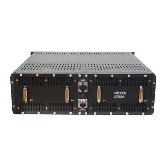
E82.C256K Series Piezo Controller User Manual 2.1 Features Adopt high thermal conductivity radiator for forced wind cooling, improve heat transfer ratio, heat dissipation efficiency and MTBF of the driver in limited space. The drive circuit adopts "module" design, each module integrates 16 drive output channels. - Page 7 2.1.2 Panel ⑤ ② ④ ① ③ ⑥ ⑦ Symbol Function Interface 1 Output drive Interface 1 drive output interface, (74pin connector) CH1-CH64 output terminal. Interface 2 Output drive Interface 2 drive output interface, (74pin connector) CH65-CH128 output terminal. Interface 3Output drive Interface 3drive output interface, (74pin connector) CH129-CH192 output terminal.
-
Page 8: Block Diagram
E82.C256K Series Piezo Controller User Manual 2.2 Block Diagram E82.C256K is composed of power supply module, main control module, power amplification module, heat dissipation module and control card. 2.3 Circuit Composition 2.3.1 Power supply The power supply module is designed based on DC/DC switching power supply, which can convert +127V, -29V, ±15V, +5V, +12V direct current, providing power supply voltage... - Page 9 Power supply for cooling part: +12V 2.3.2 Main control The main control is composed of high-performance MCU, Ethernet interface, DA module and AD module: High performance MCU:STM32H743IIT6 chip, containing SPI and ADC interfaces; Ethernet interface: WIZnet W5500 chip; DA module: DAC8568 DIGITal-to-analog converter, 16 bits, 8 channels, ultra-low burr, voltage output type, to provide the driver module to meet the requirements of -20V~120V analog signal;...
-
Page 10: Piezo Driving Principle
E82.C256K Series Piezo Controller User Manual 2.3.3 Power Amplification Power amplifier is composed of voltage amplifier circuit and power amplifier circuit, the 0~5V analog signal provided by the DA module is enlarged into -20V~+120V high voltage output, Case (1) single channel output power ≮ 5W. The most power amplifying circuit is the heating element, which is connected with the heat conduction department, and expends the heat through the heat dissipation module. -
Page 11: Ethernet Communication Interface And Software Protocol
2.5 Ethernet Communication Interface and Software Protocol W5500 Ethernet interface is used for E82.C256K ,On the one hand, in order to meet the compatibility problem of the communication control card with the user and the bandwidth requirement of 100 megabit Ethernet;On the other hand, to cooperate with MCU to maximize work efficiency. - Page 12 E82.C256K Series Piezo Controller User Manual Communication interface A hundred Megabyte Ethernet interface 19 inches 8U case Volume:480mm(W)×134mm(H)×495mm(D) Weight requirement 26kg Short-circuit protection Each channel has short circuit protection function Output connectors to the resistance between the Ground resistance "ground" Ω ≯ 1 2.6.2 Condition...
-
Page 13: Power Calculation
CoreMorrow immediately.Please take good care of the original packaging materials for subsequent maintenance. -
Page 14: Electrical Inspection
E82.C256K Series Piezo Controller User Manual ● Connect E82.C256K using the supplied power cable. ● If the power cable provided by our company must be replaced, please use a power line of sufficient diameter size and ensure effective connection. Attention! Improper installation or placement of E82.C256K may result in high temperature or overheating during operation! ●... -
Page 15: Cable Connection
should be kept indoors for more than half an hour and then electrified! 1)Connect the interface. 2) Connect the power line. 3)Turn on the green light of the chassis panel. 4)Connect the software. 3.4 Cable Connection After the system has passed the electrical inspection, the piezo actuator can be connected to the system for corresponding operation.Follow these steps: Turn off system equipment. -
Page 16: Transportation And Storage
5.1 Disposal When disposing of old equipment, please abide by the national regulations and local regulations.Please dispose of the old equipment properly. Please contact CoreMorrow for the upgrade and replacement of old equipment in order to meet the customer's handling of system products. -
Page 17: After-Sales Service
Any part of E82.C256K is dismantled, there will be no warranty service. E82.C256K is a precision instrument which should be handled with care. In case of any problem, please record the problem and contact CoreMorrow to be repaired by professional technicians. -
Page 18: Appendix
E82.C256K Series Piezo Controller User Manual Appendix Appendix1: Drawings... -
Page 19: Appendix2: Block Diagram
Appendix2: Block Diagram... -
Page 20: Appendix 3: Network Communication Protocol For Piezo Actuator
E82.C256K Series Piezo Controller User Manual Appendix 3: Network Communication Protocol for Piezo Actuator UDP packet structure Data field Type Length(byte) Description frame byte Seven 0xFF followed by one 0xFE header length unit :bytes.Length = the packet length of bytes from the Command... - Page 21 After the connect is successful, if AliveTest function is available, the upper computer will send at least one command to the PZT driver at least every 2 seconds,If there is no command, send alive command. If the piezo actuator does not receive at least one command within 5 seconds, it means that the upper computer has left.The piezo alive...
- Page 22 E82.C256K Series Piezo Controller User Manual Command = SetDriveVec, Set the drive vector of the piezo actuator Byte offset address in Type the data area the DA of no. 0 logic driving channel DAV[0] uint 16 output the DA of no. 256 logic driving...
- Page 23 Command = string command Byte offset address in the Type Length(byte) comment data area The length of the string command varies depending The number of on the command.When the String ASCII characters in a length is less than an even command string command number, a binary 0 is added...
-
Page 24: Appendix 4: Piezo Actuator String Command
E82.C256K Series Piezo Controller User Manual Appendix 4: Piezo Actuator string command Command format: < address/command [: parameter]> Address: host address. Slot address, address can be located to the specific circuit board. The host address starts at 1, and slot address 0 is the control board. - Page 25 Returns: < 0.0 / get_DriveScope: min = Vmin, Max = Vmax > Set the single-channel DA output value < address /set_DA:CH=DAV > CH: The drive channel number on the drive board, starting at 0. DAV: DA output value;0 ~ 65535. Reads the current DA output value of a single channel <...
- Page 26 E82.C256K Series Piezo Controller User Manual < address /set_DriveSource: CH=SignalSource> SignalSource: the SignalSource that drives the channel.0: DAC, 1: BNC. Read Select the monitor channel < address /set_monitor: CH > CH: Outputs channel CH as a monitoring signal. read Enables real-time sending of the current driver vector <...
- Page 27 <2.8/save> <1.7/get_CHMap:20> <1.8/set_offset:2=567> <1.9/get_offset> <2.0/set_gain:2=567> <2.1/get_gain> <2.2/set_DriveSource:2=1> <2.3/set_monito:4> <2.4/get_monito> <2.5/set_GetDriveVec> <2.6/get_error> <2.7/get_msg> <2.8/save>...
-
Page 28: Appendix 5: Main Technical Indicators
E82.C256K Series Piezo Controller User Manual Appendix 5: Main technical indicators Items Parameter Input voltage (V) AC 220V Output channel number 256 channels Catic photoelectric connector: J24H-74ZKH ×4 Output interface 220VAC power supply connector: JY27467T13E03PN - H x 1 Single channel output voltage -20V ~... -
Page 29: Appendix6: Connector Pin Definition
Appendix6: Connector pin definition J24H series miniature rectangular electrical connectors Introduction Meets GJB2446 The contact couple is the elastic strand insertion needle (braid needle) and the rigid socket, so the contact is reliable. Metal shielded enclosure with wire clip and quick locking device. Press joint, welding, straight type, bend type printed board welding various end - joint forms. - Page 30 E82.C256K Series Piezo Controller User Manual Impact: 980 m/S2 Random vibration: power spectral density 0.4G2/Hz, total added velocity RMS 23.1G Dielectric withstand voltage: 800V (9, 19, 25, 37, 52, 74 cores) 1000V(15, 26, 38, 51 cores) Arrangement of contacts ( pin insertion surface of pin insulator)
-
Page 31: Appendix7: Connector Wire Sequence Table
Appendix7: Connector wire sequence table ⑤ ② ④ ① ③ ⑥ ⑦ Symbol Function Interface 1 Output drive Interface 1 drive output interface, (74pin connector) CH1-CH64 output terminal. Interface 2 Output drive Interface 2 drive output interface, (74pin connector) CH65-CH128 output terminal. Interface 3Output drive Interface 3drive output interface, (74pin connector) -
Page 32: Appendix8: System Composition List And Vulnerable And Consumable Parts List
E82.C256K Series Piezo Controller User Manual Appendix8: System composition list and vulnerable and consumable parts list Moudle Description Quantity Remark 19inches 3U height case Volume 480mm(W)×134mm(H)×445mm(D) (custom) ① High voltage power supply: +127V, -29V Power supply ② Low-voltage power supply: +3.3V, +5V,...
Need help?
Do you have a question about the E82.C256K Series and is the answer not in the manual?
Questions and answers