Table of Contents
Advertisement
Quick Links
Advertisement
Table of Contents

Related Manuals for Coremorrow E00/E01 series


Summary of Contents for Coremorrow E00/E01 series
- Page 1 E00/E01 Series Modular Piezo Controller User Manual Version: V1.0 Date: 2017-08 This document describes the following products: ■ E00、E01 Chassis with Power Supply ■ E03、E05、E06、E07 Amplifier Modules ■ E09 PZT Sensor/Piezo Servo Control Modules ■ E17/E18 Display / Interface Modules...
- Page 2 DECLARATION Declaration! This user manual is a integrated user manual of the E00/E01 series piezoelectric controller. Customers can use the different modules to assemble and use. Please read this user manual carefully before using this controller. Follow the instructions in the manual during use. If there is any problem, please contact us for technical support.
-
Page 3: Table Of Contents
Contents 1.Safety ............................2 1.1 Design use ........................... 2 1.2 Safety Instructions ........................ 2 1.3 User Manual Notes ....................... 2 2. Introduction ..........................3 2.1 Overview ..........................3 2.2 System Component Module ....................5 2.4 Product Series Introduction ....................6 ...................... -
Page 4: Safety
E00/E01 Series Modular Piezo Controller User Manual 1.Safety 1.1 Design use The E00/E01 system is designed for integrated user use and laboratory equipment. Keep the surface of the E00/E01 system clean and dry. Do not operate in a humid or Large electrostatic environment. -
Page 5: Introduction
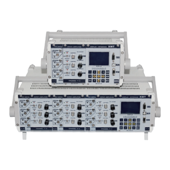
2.1 Overview Figure 1. E00/E01 Control System The E00/E01 series piezoceramic controller is a high quality drive power source designed for piezoelectric ceramic actuators. It provides piezoelectric ceramics with high stability, high resolution voltage, excellent frequency response and extremely low static ripple. E00/01 Series Products with multiple control modes, multiple models, and multiple configurations can meet the needs of different users. - Page 6 E01 control system can combine up to 9 independent control channels. Standard modular design provides great flexibility Thanks to its modular construction, the E00/E01 series of piezo controllers can be used in many different applications. Many types of sensor modules can be mounted in a 19" / 9.5" chassis.
-
Page 7: System Component Module
in conjunction with SGS resistance strain gauge/LVDT inductive/CAP capacitive sensors, fully synchronized with the sensor, reduces cycle times and provides high resolution . Fast response Dynamic Use Operation PZT movement requires high charging and discharging currents, and the power amplification module can solve these problems through different power supply channels. All power amplifier modules provide short-term peak current that gives PZT movements with extremely short rise and settling times. -
Page 8: Product Series Introduction
E00/E01 Series Modular Piezo Controller User Manual Sensor control module E09.S1 PZT sensor control module, SGS sensor, single channel E09.L1 PZT sensor control module, LVDT sensor, single channel E09.C1 PZT sensor control module, CAP sensor, single channel E09.S2 PZT sensor control module, SGS sensor, three channels E09.L2 PZT sensor control module, LVDT sensor, three channels... - Page 9 modules. A series products (open loop) - power amplification module The PZT sensor control module slot and display/interface slots are unused and covered by the blank panel. The A series products consist only of power amplifier modules and chassis and multiple power modules.
-
Page 10: Product Series Picture
E00/E01 Series Modular Piezo Controller User Manual panel of the position sensing module. The other end is connected to the measuring instrument for detection. The connector red fish clip is the positive pole and the black fish clip is the negative pole. -
Page 11: Compatibility Note
C Series 1×E01 chassis and power 1×E00 chassis and power 1×E01 chassis and power supply module supply module supply module 1×E05 power amplifier 3×E03 power amplifier 1×E03 power amplifier module module module 1×E17 display 1×E17 display 1×E17 display interface module interface module interface module D Series... -
Page 12: System Block Diagram
E00/E01 Series Modular Piezo Controller User Manual other position and cause unnecessary loss. Older modular components combined with newer modular components in the E00/E01 system can cause system failures and damage to the system. If you need to replace a new E00/E01 system chassis or module assembly, please contact our customer service department. -
Page 13: Maximum Rating
2.8 Maximum rating Basic nominal data for the operation of the E00/E01 system: Max operating voltage Max output power Models Operating frquency range range 200 ~ 240VAC E00 system 50-60Hz 136VA (fuse:2A-250V) 200 ~ 240VAC E01 system 50-60Hz 66VA (fuse:2A-250V) 2.9 Environmental conditions The environment in which the E00/E01 system operates must comply: Environmental conditions... -
Page 14: System Operation And Safety Measures
●PZT output line (depending on the presence or absence of piezo actuators, nanopositioning stage, micro-motion stage) ● E00/E01 Series Piezo Controller User Manual (this document) 3.1.2 If one or more E09 modules are installed, the following items are included: ● Sensor monitoring cable for E09.Sx/Lx models 3.1.3 If one or more E17/E18 modules are installed, the following items are included:... -
Page 15: Electrical Inspection
If you find oscillation, please proceed as follows: ● When using the closed loop operation mode, please turn off the servo mode immediately. ● When using open loop operation, stop driving the piezoelectric actuator immediately. ● Turn off the E00/E01 system power. NOTE! E00/E01 system is directly powered, and there will be thermal instability! ●... -
Page 16: Connecting Cables
E00/E01 Series Modular Piezo Controller User Manual the voltage display. The voltage display reading is the current PZT output voltage, and the value of the displacement or angle is not meaningful because the piezoelectric actuator and sensor are not connected. -
Page 17: Module Description
after the corresponding amplification factor. The output signal can be controlled by manual and DC offset OFFSET potentiometer. In open loop mode, the display module will display the voltage reading information in real time. The information of the position reading is not meaningful at this time.) Turn on the power. -
Page 18: Chassis And Power Supply
E00/E01 Series Modular Piezo Controller User Manual 4.1 Chassis and power supply 4.1.1 E00 System Chassis Technical Specifications Models E00.00 Piezoelectric controller system for 19-inch chassis: Function Including power amplifier module, PZT sensor control module, display / interface module Channel... - Page 19 4.2.2 E01.00 Chassis Module Dimensional Drawing 360mm 280mm 4.3 E03 HVPZT Power Amplifier Module Danger! The E03 power amplifier module can output high voltages, and touching this high voltage can cause serious or even fatal injuries. Only qualified professional technicians can install, operate, maintain and clean the E03 Power Amplifier Module! 4.3.1 Introduction to the front panel Figure 3.
- Page 20 E00/E01 Series Modular Piezo Controller User Manual Identifier Model Function The power amplifier module works abnormally. Red light on: the power amplifier module is in OVER LED red an overcurrent state; Red light off: The power amplifier module is operating properly...
- Page 21 4.4 E05 HVPZT Power Amplifier Module Danger! The E05 power amplifier module can output high voltages, and touching this high voltage can cause serious or even fatal injuries. Only qualified technicians can install, operate, maintain and clean the E05 Power Amplifier Module! 4.4.1 Introduction to the front panel Figure 6.E05.00 Power Amplifier Module Figure 7.
- Page 22 E00/E01 Series Modular Piezo Controller User Manual 4.4.2 Load - Voltage - Frequency Graph 0.1uf 0.3uf 1.8uf 3.6uf 7.2uf 14uf 25uf 1000 10000 100000 Frequency[Hz] Figure 8. E05.00 Load - Voltage - Frequency Graph 4.5 E06 HVPZT Power Amplifier Module Danger! The E06 power amplifier module can output high voltages, and touching this high voltage can cause serious or even fatal injuries.
- Page 23 Identifier Model Function The working status indication of the power amplifier module: POWER LED green Green light on: E06 operating normally; Green light off: E00/E01 system is off The power amplifier module works abnormally. The red light is on: the power amplifier module is in OVER LED red an overcurrent state;...
- Page 24 E00/E01 Series Modular Piezo Controller User Manual 4.6 E07 HVPZT Power Amplifier Module Danger! The E07 power amplifier module can output high voltages, and touching this high voltage can cause serious or even fatal injuries. Only qualified technicians can install, operate, maintain and clean the E07 Power Amplifier Module! 4.6.1 Introduction to the front panel...
- Page 25 NOTE! DANGER! Directly measure the PZT OUTPUT end or both ends of the accessory cable with an instrument such as an oscilloscope. When the output voltage exceeds 300V, pay attention to the measurement voltage range of the oscilloscope and other instruments, otherwise it will damage your measuring instrument! 4.6.2 Load - Voltage - Frequency Graph 0.1uf...
- Page 26 E00/E01 Series Modular Piezo Controller User Manual The combined bipolar power amplifier module is a combination of two unipolar high-voltage operational amplifiers. The principle is shown in Figure 8. The input voltage value of amplifier CH1 and amplifier CH2 are same , but with opposite polarity of the output voltage. One end of PZT piezoelectric ceramic or capacitive load is connected to the output electrode end of amplifier CH1, and the other end is connected to the output electrode end of amplifier CH2.
- Page 27 Uo1= Ui×A Input Voltage Output Voltage Amplification Factor High Voltage Operational Amplifier PZT/ Capacitive Load High Voltage Operational Amplifier Amplification Factor Uo2= -(Ui×A) Output Voltage Figure 14 . Block diagram of the combined two-electrode piezoelectric ceramic controller 4.7.2 Front Panel Introduction Figure 15.
- Page 28 E00/E01 Series Modular Piezo Controller User Manual Identifier Model Function The working status indication of the power amplifier module: POWER LED green Green light on: operating normally; Green light off: E00/E01 system is off The power amplifier module works abnormally.
- Page 29 clip being the signal input line and the black being the input ground. The matching cable at the output PZT OUTPUT terminal is a three-wire output. Two red clips are two independent single- electrode output lines, and the black clip is a common ground. When connecting a load such as a piezoceramic (PZT) through a three-wire output cable, carefully determine the polarity of the marking on the matching cable, otherwise the load such as piezoelectric ceramic (PZT) may be damaged.
- Page 30 E00/E01 Series Modular Piezo Controller User Manual 4.7.4 Load - Voltage - Frequency Graph 2000 1800 E07.20 1600 1400 1200 1000 0.1uf 0.3uf 1.8uf 3.6uf 7.2uf 14uf 25uf 1000 10000 100000 Frequency[Hz] Figure 17. E07.20 Load - Voltage - Frequency Graph 4.7.5 Pin Definition...
-
Page 31: E09 Pzt Sensor Control Module
Pin electrode output voltage conditions, including 1800V and 600V voltage output parameter table E07.20 Combined bipolar power amplifier module 1800V Channel CH1 (Pin 1) CH2 (Pin 2) CH1 and CH2 Input voltage Ui 0 ~ +10V 0 ~ +10V 0 ~ +10V Nominal output voltage Uo 0 ~ +900V 0 ~ -900V... - Page 32 E00/E01 Series Modular Piezo Controller User Manual Figure 20. E09.Sx/Lx Piezoelectric Servo Control Module 4.8.1 Introduction to the front panel of SGS sensor and LVDT sensor module Identifier Model Function Sensing output (SENSOR MONITOR end) signal RANGE 25-turn Potentiometer amplitude range adjustment hole, generally no adjustment.
- Page 33 4.8.2 Introduction to the front panel of the capacitive sensor module Figure 21. E09.C1 Piezoelectric Servo Control Module Identifier Model Function POWER LED green Power on indication SENSOR Sensor input signal of the probe of the capacitive sensor The sensing output signal terminal that can determine the SENSOR displacement value of the piezoceramic or micro-motion MONITOR...
- Page 34 E00/E01 Series Modular Piezo Controller User Manual 4.8.3 Pin Definition E09.Sx sensor input connector - LEMO ERA.0S.304.CLL The pin signals are defined as follows: Pin No. Cable color Pin definition +10V White Sensor feedback signal 1 Blue Sensor feedbak signal 2 Black Figure 22.
- Page 35 E09.C1 sensing module connector - 32 pin DIN41612 European connector (male) (1) European connector as shown below: (2) The pins are defined as follows: Pin Number Pin Number Pin Definition +15VDC -15VDC Uout: 0~10V Uout: 0~10V Note: The unlabeled pin is empty.
- Page 36 E00/E01 Series Modular Piezo Controller User Manual 4.8.4 Capacitive sensor image and fixed way (1) The sensor probe is like a cylindrical structure and is equipped with an integrated wire joint. The capacitive sensor probe is as shown in the following figure: (2) The cylindrical probe used in the capacitive sensor module can be installed and fixed by a clamp, and the probe can be flush with the fixed surface or partially protruded outward.
-
Page 37: E17/E18 Display And Interface Module
of unstable measurement data! When installing the probe of the capacitive sensor, consider the safe distance from the moving contact surface to prevent damage to the probe due to too close distance! When applying the board module, the working power supply should be powered by a linear power supply or a switching power supply with extremely low ripple noise! Do not drag SGS (resistance strain gauge), LVDT (inductive), CAP (capacitive) sensor cables! Please strictly abide by the signal definition of each sensor, do not arbitrarily change the pin line... - Page 38 E00/E01 Series Modular Piezo Controller User Manual 4.9.1 Front Panel Introduction Figure 25. E17/E18 Display and Interface Module Identifier Model Function The window is a blue-screen white-character liquid crystal Chinese character display. You can observe the window to understand the working status of the...
- Page 39 Identifier Model Function The interface cable will lead out four pin lines, black for ground and others for 1~3 channel for external MDR14 connection logic control and signal acquisition. A program writer Digital In/Out socket interface that can be used for internal retention. ●For details, refer to the E17/E18 Software Operation User's Manual.
-
Page 40: Electrical Operation Formula
E00/E01 Series Modular Piezo Controller User Manual Yellow I/O signal of CH3 Black Operating voltage ground Operating voltage ground Prompt! The unlabeled pins in the above connectors are empty signals. 5. Electrical operation formula Power amplification module power calculation formula Average power (sine wave operation) Pa ≈... -
Page 41: Transportation And Storage
Note! The E00/E01 system relies on 200 to 240V AC to work, and touching the line voltage can cause fatal injuries! If the fuse fails and the entire system is not working, unplug the power cord from the E00/E01 system and replace it with a new one. The fuse is model AC250V-3A and the power supply connection and fuse are located on the right side of the rear panel of the E00/E01 chassis. -
Page 42: Service And Repair
E00/E01 Series Modular Piezo Controller User Manual 7. Service and repair 7.1 Disposal of used equipment Please follow the national regulations and local regulations when handling old equipment. Please handle the old equipment correctly and environmentally. In order to meet the customer's handling of system products, the company provides upgrades and replacements for old equipment, please contact your sales engineer or contact customer service department. -
Page 43: System Accessories
8. System accessories PZT output coaxial cable E05.20 Output cable (aviation E07.20 output cable (aviation (LEMO) plug) plug) negative signal Positive signal USB cable Sensor output cable Serial cable (9-pin to 9-hole) (Type A male to B male) Analog input cable Digital I/O port cable (MDR14) Power cable... -
Page 44: Customer Service
E00/E01 Series Modular Piezo Controller User Manual 9. Customer Service If you have questions about the products you are currently using, please let us know the following information: Product model number and related number Controller model for this product Software driver version for this product Computer operating system 10.
Need help?
Do you have a question about the E00/E01 series and is the answer not in the manual?
Questions and answers