Table of Contents

Related Manuals for StarTech.com A2-LAPTOP-DESK-MOUNT


Summary of Contents for StarTech.com A2-LAPTOP-DESK-MOUNT
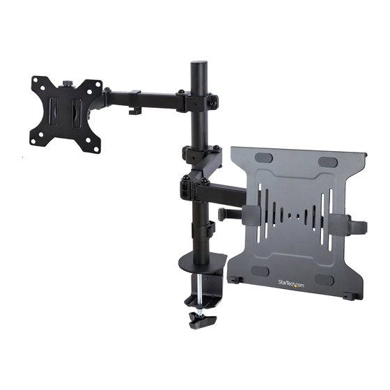
- Page 1 Articulating Monitor Arm and Laptop Holder Actual product may vary from photos User Manual SKU: A2-LAPTOP-DESK-MOUNT For the latest information and specifications visit www.StarTech.com/A2-LAPTOP-DESK-MOUNT Manual Revision: 11/11/2021...
- Page 2 This manual may make reference to trademarks, registered trademarks, and other protected names and/or symbols of third-party companies not related in any way to StarTech.com. Where they occur these references are for illustrative purposes only and do not represent an endorsement of a product or service by StarTech.com, or an endorsement of the product(s) to which this manual...
-
Page 3: Safety Statements
Säkerhetsåtgärder • Installation och/eller montering får endast göras av behöriga yrkespersoner och enligt gällande lokala förordningar för säkerhet och byggnormer. To view manuals, videos, drivers, downloads, technical drawings, and more visit www.startech.com/support... -
Page 4: Warning Statements
• Dra inte åt skruvarna för hårt när du monterar produkten. Om du måste ta i när du skruvar åt kan du sluta skruva åt. • Det krävs Monitorå personer för att montera produkten. Försök inte montera produkten och installera utrustning utan hjälp. To view manuals, videos, drivers, downloads, technical drawings, and more visit www.startech.com/support... - Page 5 • Gevaar voor beknelling! Houd uw vingers weg van de bewegende onderdelen als u. 注意 • 必ず取扱説明書に従って本製品の組み立てを行って下さい。 • 最初に取扱説明書を最後まで読み、 本製品の組み立て方をすべて理解して から組み立て作業を始めて下さい。 • 本製品で定められた最大積載重量を超えないようにして下さい。 最大積載 重量をオーバーした場合、 怪我をする恐れや器物破損の恐れがあります。 • モニターマウントの耐荷重 : 8 kg (17.6ポンド) • ラップトップマウントの耐荷重 : 4.5 kg (9.9 lb.) To view manuals, videos, drivers, downloads, technical drawings, and more visit www.startech.com/support...
- Page 6 • Assemblez ce produit conformément aux instructions. • Lisez tout le manuel et assurez-vous que vous comprenez les instructions avant de commencer à assembler et utiliser ce produit. To view manuals, videos, drivers, downloads, technical drawings, and more visit www.startech.com/support...
- Page 7 • Antes de começar a mover o carro, certifique-se de que desbloqueia os rodízios. To view manuals, videos, drivers, downloads, technical drawings, and more visit www.startech.com/support...
- Page 8 • Überschreiten Sie nicht die Tragkraft dieses Produkts. Ein Überladen dieses Produkts kann zu Verletzungen oder zur Beschädigung des Produkts führen. • Gewichtskapazität der Monitorhalterung: 8 kg (17,6 lb.) • Belastbarkeit der Laptophalterung: 4,5 kg (9,9 lb.) To view manuals, videos, drivers, downloads, technical drawings, and more visit www.startech.com/support...
- Page 9 Gewicht der Geräte, die Sie hinzufügen möchten, tragen kann. • Stellen Sie sicher, dass die Rollen entriegelt sind, bevor Sie den Wagen in Bewegung setzen. • Einklemmgefahr! Halten Sie Ihre Finger fern von beweglichen Teilen. To view manuals, videos, drivers, downloads, technical drawings, and more visit www.startech.com/support viii...
-
Page 10: Table Of Contents
Attach the Monitor Mount Assembly to the Arm (B) ..............13 Attach the Laptop Tray (C) to the Pole Assembly ................14 Attach the Laptop Arms ......................... 14 To view manuals, videos, drivers, downloads, technical drawings, and more visit www.startech.com/support... - Page 11 Adjust the Swivel Angle of the Laptop/Monitor ................19 Rotate the Monitor ........................... 19 Warranty Information ................20 To view manuals, videos, drivers, downloads, technical drawings, and more visit www.startech.com/support To view manuals, videos, drivers, downloads, technical drawings, and more visit www.startech.com/support...
-
Page 12: Product Diagram
Product Diagram Front View Pole (G) Cable Management Clip (I) Arm (B) VESA Mount Laptop Arm Clip (D) Grommet Mount Laptop Tray (C) Desk Desk Clamp(F) Mount To view manuals, videos, drivers, downloads, technical drawings, and more visit www.startech.com/support... -
Page 13: Product Dimensions
Product Dimensions Front View Product Information Requirements For the latest manuals, product information, technical specifications, and Declarations of Conformance, please visit: www.StarTech.com/A2-LAPTOP-DESK-MOUNT Phillips Head Screwdriver • To view manuals, videos, drivers, downloads, technical drawings, and more visit www.startech.com/support... -
Page 14: Package Contents
Qty: 1 Qty: 2 Cable Laptop Tray Grommet Clamp Grommet Base Management Mounting Screws Plate (K) Plate (J) Clip (I) To view manuals, videos, drivers, downloads, technical drawings, and more visit www.startech.com/support Qty: 1 Qty: 1 Qty: 1 Qty: 4... - Page 15 4 mm Hex Key (P) Pole Mounting VESA Mount Rubber Pads (N) Screws (O) Knobs (M) Qty: 1 Qty: 5 Qty: 3 Qty: 2 6 mm Hex Key (Q) M4 x 12 mm M4 x 16 mm M5 x 12 mm Screws (M-A) Screws (M-B) Screws (M-C)
-
Page 16: Installation
Attach the Pole Cap (H) to the Pole (G) Figure 1 Insert the Pole Cap (H) into the end of the Pole (G) that does • not feature any screw holes. (Figure 1) To view manuals, videos, drivers, downloads, technical drawings, and more visit www.startech.com/support... -
Page 17: Attach The Pole (G) To The Mounting Surface
Mounting Surface (e.g. Desk or Table). 4. Slide the Desk Pole Assembly Clamp onto the Mounting Surface. 5. Tighten the Hand Screw, located on the Desk Pole Assembly, by hand, until hand-tight. To view manuals, videos, drivers, downloads, technical drawings, and more visit www.startech.com/support... -
Page 18: Mounting Option #2 - Grommet Mount
Slide the Grommet Clamp Plate (K) over the end of the Hand Screw, completing the Grommet Hand Screw. Affix the Rubber Pads (N)(x5) to the side of the Grommet Base Plate (J) that does not feature the Peg. To view manuals, videos, drivers, downloads, technical drawings, and more visit www.startech.com/support... -
Page 19: Attach The Arms (B) To The Pole Assembly
Adjustment Screw Figure 4 Slide one Arm (B) onto the Pole Assembly, ensuring the hole in the VESA Mount Attachment Point is oriented towards the top. (Figure 4) To view manuals, videos, drivers, downloads, technical drawings, and more visit www.startech.com/support... -
Page 20: Mount The Display
Remove any Screws or Place Holders from the VESA Mounting Holes on the back of the Monitor. (Figure 5) Note: Be careful not to remove any of the Screws holding the Monitor’s Casing together. To view manuals, videos, drivers, downloads, technical drawings, and more visit www.startech.com/support... - Page 21 Note: Do not over-tighten the Screws. If you encounter resistance while you’re tightening the Screws, stop tightening. Failure to do so could result in damage to the Monitor. To view manuals, videos, drivers, downloads, technical drawings, and more visit www.startech.com/support...
- Page 22 100 x 100 mounting pattern. Note When attached, the VESA Attachment Tab, located on the VESA Mount (A), should be positioned toward the top of the VESA Mount (A). To view manuals, videos, drivers, downloads, technical drawings, and more visit www.startech.com/support...
- Page 23 Note: Do not over-tighten the Screws. If you encounter resistance while you’re tightening the Screws, stop tightening. Failure to do so could result in damage to the Monitor. To view manuals, videos, drivers, downloads, technical drawings, and more visit www.startech.com/support...
-
Page 24: Attach The Monitor Mount Assembly To The Arm (B)
Insert one VESA Mount Knob (M) through the hole in the VESA Attachment Tab and into the VESA Mount Attachment Point and tighten, by hand, until hand tight. (Figure 8) To view manuals, videos, drivers, downloads, technical drawings, and more visit www.startech.com/support... -
Page 25: Attach The Laptop Tray (C) To The Pole Assembly
Laptop atop the Laptop Tray (C) and make adjustments to the Laptop Arm Clips (D) as necessary. Remove the Laptop before proceeding to the next step. To view manuals, videos, drivers, downloads, technical drawings, and more visit www.startech.com/support... -
Page 26: Attach The Vesa Mount (A) To The Laptop Tray (C)
VESA Mount (A) and into the Laptop Tray (C), and tighten, using a Phillips Head Screwdriver, to complete the Laptop Mount Assembly. Attach the Laptop Mount Assembly to the Arm (B) Figure 11 To view manuals, videos, drivers, downloads, technical drawings, and more visit www.startech.com/support... -
Page 27: Mount The Laptop
Place a Laptop atop the Laptop Mount Assembly and collapse the Laptop Arm Clips inwards, until they are flush with the sides of the Laptop. Lock the Laptop Arm Clip Lock Tabs. To view manuals, videos, drivers, downloads, technical drawings, and more visit www.startech.com/support... -
Page 28: Cable Management
Slide the 4 mm Hex Key (P) and the 6 mm Hex Key (Q) into • the Tool Slots, located on the Cable Management Clip (I). (Figure 14) To view manuals, videos, drivers, downloads, technical drawings, and more visit www.startech.com/support... -
Page 29: Operation
Tilt Adjustment Screw, using the 6 mm Hex Key (Q). (Figure 15) Note: Hold the Monitor while adjusting the tilt angle. To view manuals, videos, drivers, downloads, technical drawings, and more visit www.startech.com/support... -
Page 30: Adjust The Swivel Angle Of The Laptop/Monitor
Monitor Mount Assembly by hand. No tools are required to complete this adjustment. Rotate the Monitor Rotate the Monitor by hand. No tools are required to • complete this adjustment. To view manuals, videos, drivers, downloads, technical drawings, and more visit www.startech.com/support... -
Page 31: Warranty Information
Limitation of Liability In no event shall the liability of StarTech.com Ltd. and StarTech.com USA LLP (or their officers, directors, employees or agents) for any damages (whether direct or indirect, special, punitive, incidental, consequential, or otherwise), loss of profits, loss of business, or any pecuniary loss, arising out of or related to the use of the product exceed the actual price paid for the product. - Page 32 Hard-to-find made easy. At StarTech.com, that isn’t a slogan. It’s a promise. StarTech.com is your one-stop source for every connectivity part you need. From the latest technology to legacy products — and all the parts that bridge the old and new — we can help you find the parts that connect your solutions.
Need help?
Do you have a question about the A2-LAPTOP-DESK-MOUNT and is the answer not in the manual?
Questions and answers