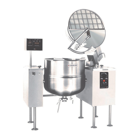
Cleveland (T) MKDL-100-T (-CC) Operator's Manual
Direct steam mixer kettles
Hide thumbs
Also See for (T) MKDL-100-T (-CC):
- Specifications (2 pages) ,
- Operator's manual (85 pages)
Table of Contents
Advertisement
Operators Manual
Installation, Operation & Service
Direct Steam Mixer Kettles
MODELS: (T) MKDL-40-T (-CC)
(T) MKDL-60-T (-CC)
(T) MKDL-80-T (-CC))
(T) MKDL-100-T (-CC)
(T) MKDL-125-T (-CC)
(T) MKDL-150-T
(-CC)
™
Cleveland
1333 East 179th St., Cleveland, Ohio, U.S.A. 44110
Phone: (216) 481-4900 Fax: (216) 481-3782
Enodis
Visit our web site at www.clevelandrange.com
SE95018 Rev. 5
Advertisement
Table of Contents

Related Manuals for Cleveland (T) MKDL-100-T (-CC)


Summary of Contents for Cleveland (T) MKDL-100-T (-CC)
- Page 1 Operators Manual Installation, Operation & Service Direct Steam Mixer Kettles MODELS: (T) MKDL-40-T (-CC) (T) MKDL-60-T (-CC) (T) MKDL-80-T (-CC)) (T) MKDL-100-T (-CC) (T) MKDL-125-T (-CC) (T) MKDL-150-T (-CC) ™ Cleveland 1333 East 179th St., Cleveland, Ohio, U.S.A. 44110 Phone: (216) 481-4900 Fax: (216) 481-3782 Enodis Visit our web site at www.clevelandrange.com SE95018 Rev.
-
Page 2: Gas Appliances
For your safety Keep clear of pressure relief discharge. Inspect unit daily for proper operation. Surfaces may be extremely hot! Use protective equipment. Do not lean on or place objects on kettle lip. Shut off power at main fuse disconnect prior to servicing. -
Page 3: Installation
INSTALLATION GENERAL Installation of the kettle must be accomplished by qualified installation personnel working to all applicable local and national codes. Improper installation of product could cause injury or damage. This unit is built to comply with applicable standards for manufacturers. -
Page 4: Moving Unit
Shim as required to make level with center console (front and back) 4"x4" or larger (front and back) Skid MOVING UNIT 1. While still on skid, move unit as close to final installation position as possible. 2. Prepare unit for lifting as shown in diagram. 3. -
Page 5: Electrical Service Connections
⇒ D/ Lower bridge. ⇒ E/ Bridge pins should enter pin hole on kettle perfectly, If not return to step 1 and repeat leveling steps. ⇒ F/ Raise bridge and swing to far right (for twin mixers only). ⇒ G/ Repeat steps D and E (for twin mixers only). -
Page 6: Piping Schematic
PIPING SCHEMATIC STEAM REQUIREMENTS FOR KETTLES Kettle Cap. Kettle 25 psi Steam 265°F U.S. Gal. Dia. Lbs./Hr. 26" 29.5" 33" 36" 40" 40" Steam requirements are maximum per hour. If more than one unit is on the same line then add the steam usage for each one to reach a total. STEAM PIPE SIZING Required pipe length in feet/meters Steam Required... -
Page 7: Quality Assurance Checklist
QUALITY ASSURANCE Follow this list only after all other installation steps are completed. Some steps require the use of equipment. Follow operating instructions. The following will be performed before the unit is connected to utilities: 1. Visual Examine unit for scratches, dents, or other defects. 2. - Page 8 OPTIONAL CONTROLS Some units may not have the following items to test 13. Meter Complete this test using markings on mixer arm or a measuring strip if there are no markings on the unit. Test the meter at the following values up to capacity (Should be approx.
-
Page 9: Operating Instructions
OPERATING INSTRUCTIONS Operating Controls & Indicators for Standard Direct Steam Mixer Kettles ITEM NO. DESCRIPTION FUNCTION Air Quick Connect ..Connection for air to food pump. Air Regulator ....Opens and closes air operated product discharge valve (Item 10). Hand Wheel . - Page 10 Operating Controls & Indicators for Cook Chill Direct Steam Mixer Kettles ITEM NO. DESCRIPTION FUNCTION Air Quick Connect ..Connection for air to food pump. Air Regulator ....Opens and closes air operated product discharge valve (Item 10). Hand Wheel .
-
Page 11: General Operation
Operating Suggestions Cleveland Range Mixer Kettles are simple and safe to operate. The following tips will allow you to maximize the use of your new mixer. 1. To achieve optimum performance on tilting kettles; Before applying steam to a cold kettle, open the DRAIN COCK to drain condensate from the kettles jacket. -
Page 12: Discharge Valve
Discharge Valve 1. For air valve: turn AIR REGULATOR clockwise to open, or counterclockwise to close. 2. For butterfly valve: push handle in and pull upwards to open. Adding Water Manually 1. Locate FAUCET SPOUT over desired kettle. 2. Turn on HOT or COLD WATER VALVES. -
Page 13: Mixer Kettle Operation Using Cal 9900
CAL 9900 Error View Set Point Decrease Increase CAL 9900 Controls Drawing MIXER KETTLE OPERATION USING CAL 9900 Note: Temperature probe on mixer bridge must be covered with a minimum of three inches of product to function correctly. 1. Open STEAM VALVE completely 2. - Page 14 OUT1 OUT2 ALRM Heat Cooling Manual Output 1 Output 2 OUT1 OUT2 ALRM Setpoint Minus Sign MRC 7000 Controls Drawing (1 pen) Display ˚C ˚F Pen1 key - AUTO/MAN SCROLL Key AUTO HEAT AUTO COOL UP Key DOWN Key BYPASS ACTIVE Alarm ˚C ˚F...
-
Page 15: Cleaning Instructions
CLEANING INSTRUCTIONS CAUTION SURFACES MAY BE EXTREMELY HOT! CARE AND CLEANING Cooking equipment must be cleaned regularly to maintain its fast, efficient cooking performance and to ensure its continued safe, reliable operation. The best time to clean is shortly after each use (allow unit to cool to a safe temperature). -
Page 16: Scraper Blades
SCRAPER BLADES 1. Remove retaining ring and slide scraper blades off agitator arm. 2. Place parts in a pan of warm water to soak. 3. Clean in a sink, using a warm water and mild detergent solution. 4. Rinse with fresh water. 5. -
Page 17: Stainless Steel Equipment Care And Cleaning
STAINLESS STEEL EQUIPMENT CARE AND CLEANING (Suppied courtesy of Nafem. For more information visit their web site at www.nafem.org) Contrary to popular belief, stainless steels ARE susceptible to rusting. Corrosion on metals is everywhere. It is recognized quickly on iron and steel as unsightly yellow/orange rust. -
Page 18: Warranty
SERVICE PARTS WARRANTY Our Company supports a worldwide network of Maintenance and Repair Centers. Contact your nearest Maintenance and Repair Centre for replacement parts, service, regarding the proper maintenance and repair of your cooking equipment In order to preserve the various agency safety certification (UL, NSF, ASME/Ntl. -
Page 19: Hydraulic Components
HYDRAULIC COMPONENTS Scraper Blades: KETTLE SIZE GALLONS QUANTITY Cooling Fan: Fan ..KE54860 Fan Cover . . . KE601236 Fan Guard . . . KE54861 NOTE: For Hydraulic Hoses order Part No. RT00505 and specify length required ITEM NO. - Page 20 KE51834 KE51875-3 KE51875-4 KE51875-5 KE51889 KE52222 KE52222-1 KE52223 KE52224 KE52190 KE52171 KE51844 FI05060 SE50280 FI05061 SE50094 KE51874 KE52382 KE00860 KE51622 FA95022 KE51623 SE50353 KE51624 KE50295 KE50294 FA95055-3 T40527 T40528 T40529 T40530 T40531 T40532 T405321 T405322 KE51921 KE51925 FA19506 FA19507 KE00935 KE00936 KE00937 KE00938...
-
Page 21: Remote Control Assembly
REMOTE CONTROL ASSEMBLY For Standard Direct Steam Mixer Kettles NOTE: See SWITCH CONFIGURATIONS for applicable contact cartridge/capacitor combinations and part numbers ITEM NO. PART NO. DESCRIPTION KE53479 Digital Temperature Controller and Indicator .....1 KE53257 Digital Counter . - Page 22 REMOTE CONTROL ASSEMBLY For Cook Chill Direct Steam Mixer Kettles NOTE: See SWITCH CONFIGURATIONS for applicable contact cartridge/capacitor combinations and part numbers ITEM NO. PART NO. DESCRIPTION KE53257 Digital Counter ..........1 SE50354 Pen Tip, red (pkg.
-
Page 23: Main Console Controls
MAIN CONSOLE CONTROLS For Standard Direct Steam Mixer Kettles NOTE: See SWITCH CONFIGURATIONS for applicable contact cartridge/capacitor combinations and part numbers ITEM NO. PART NO. KE52190 KE00860 KE53193 KE53377 SK50315-1 KE003209-5 KE003209-1 KE003209-7 KE52180 FA10032 FA32002 FA20000 KE95230-E DESCRIPTION Knob, Speed Control ........1 Cable and Bracket, Speed Control (includes items 9 - 13) . - Page 24 MAIN CONSOLE CONTROLS For Cook Chill Direct Steam Mixer Kettles NOTE: See SWITCH CONFIGURATIONS for applicable contact cartridge/capacitor combinations and part numbers ITEM NO. PART NO. KE52190 KE00860 KE53193 KE53377 KE003209-8 KE52180 FA10032 FA32002 FA20000 KE003209-5 KE95230-E " M DESCRIPTION Knob, Speed Control .
-
Page 25: Switch Configuration
SWITCH CONFIGURATION For Standard Direct Steam Mixer Kettles INDEX Capacitor Contactor Cartridges PART NO. KE52074 KE603208-9 KE603208-8 NOTES: For units built prior to December 2006, the complete switch assembly must be ordered (see applicable drawing). Refer to Maintenance Section for Switch Disassembly Instructions. - Page 26 SWITCH CONFIGURATION For Cook Chill Direct Steam Mixer Kettles INDEX Capacitor Contactor Cartridges PART NO. KE52074 KE603208-9 NOTES: For units built prior to December 2006, the complete switch assembly must be ordered (see applicable drawing). Refer to Maintenance Section for Switch Disassembly Instructions.
-
Page 27: Electrical Component Assembly
ELECTRICAL COMPONENT ASSEMBLY For Standard Direct Steam Mixer Kettles THERMAL OVERLOAD RELAY ITEM PART NO. DESCRIPTION KE50343-7 KE50753-10 KE51139 SK50445 KE52936 KE50750-1 KE51982 KE52055 KE52051 SK50055-1 SK50054-1 KE53838-5 KE53838-6 FA10133 FA10239 FA12500 FA10245 FA10362 FA32005 FA32006 KE02274 Component Mounting Plate ........1 Relays . - Page 28 ELECTRICAL COMPONENT ASSEMBLY For Cook Chill Direct Steam Mixer Kettles THERMAL OVERLOAD RELAY ITEM NO. PART NO. KE50343-8 KE52710 KE52835 KE50753-10 KE51139 SK50445 KE52936 KE50750-1 KE51982 KE52055 KE52051 SK50055-1 SK50054-1 KE53838-5 KE53838-6 FA10133 FA10135 FA10239 FA12500 FA10245 FA10362 FA32004 FA32005 FA32006 FA20002 KE02274...
- Page 29 PLUMBING ASSEMBLY - 10" CONSOLE ITEM NO. PART NO. DESCRIPTION KE02055-2 Steam Valve 3/4" ..........1 KE02055-4 Steam Valve 1 1/4"...
- Page 30 PLUMBING ASSEMBLY - 18" CONSOLE ITEM NO. PART NO. FI00096 F100179 F105130 KE52702 KE52701 FI00151 FI00441 FI00363 KE54834-5 SE50407 SE50401 KE54834-4 SE50410 SE50404 FI00143 KE51653 KE51654 KE52666 UR50077 FA11052 FA11060 FI00178 FI05089 KE54834-2 SE50408 SE50404 *NOTE: See SOLENOID VALVE MAINTENANCE section for further information. DESCRIPTION Union .
- Page 31 MANUAL TILT - 10" CONSOLE ITEM NO. PART NO. KE51730 KE50375 KE503751 FA19505 KE00508 FA95007-1 FA05002-6 FA95048 FA19201 KE00151 KE52833 KE00699 FA19177 FA20047 KE52191 KE52193 KE50315 FA95005 FA95008 FA30088 KE52192 DESCRIPTION Tilt Shaft Bearing ..........1 Tilt Shaft, Small Gear, 40 to 80 gal.
- Page 32 POWER TILT - 10"/12" CONSOLE...
- Page 33 POWER TILT - 10"/12" CONSOLE ITEM NO. PART NO. KE50581 KE51007 KE52192 KE52193 KE52191 FA30088 FA95008 SE00028 KE50315 FA95005 KE51730 KE00151 KE52833 KE00699 KE001182 FA95007-1 FA05002-6 FA05002-27 FA95048 FA19201 FA19177 FA20047 KE50582 KE50583 KE52832-1 SK50055-1 SK50054-1 KE50579-1 FA05002-34 KE50580 KE003209-11 KE603208-4 KE603208-7 KE603208-9...
- Page 34 WATER METER ASSEMBLY - 18" CONSOLE...
- Page 35 WATER METER ASSEMBLY - 18" CONSOLE ITEM NO. PART NO. FI05058 KE02055-2 N0640B4.5 FI00063 FI000356 KE600812-1 FI05029 KE54834-5 SE50407 SE50401 N0640B3 N0640B3.5 FI00363-3 KE51861 KE51860 FI00062 KE52173 FI05220-3 FI00179 FI05074 KE600362 N0640B1.5 FA11091 KE51369 SE00028 KE95321 KE95322 SD50097 KE51585 KE50825-12 FA05002-19 FA95022 KE51736...
-
Page 36: Flush Piston - Valve
FLUSH PISTON - VALVE (USED PRIOR TO 2003) ITEM NO. PART NO. DESCRIPTION T40430 Valve Assembly (includes parts 1 - 16) ......1 FA05000 "O"... - Page 37 FLUSH PISTON - AIR SYSTEM, 10" CONSOLE (USED PRIOR TO 2003) ITEM NO. PART NO. FA30512 FA32500 KE52697 KE52931 FI00266 FI00595-17 FI00178 FI00595-12 FI05047 KE52342 FI05167 KE52815 KE52895 KE52339 KE52932 FA32006 FA21006 FA11091 KE53209 KE53210 KE52031 KE53251 FA11144 FI05166 KE54280 KE53215 DESCRIPTION Spacer .
- Page 38 FLUSH PISTON - LUBRICATOR (USED PRIOR TO 2003) ITEM NO. PART NO. FA30512 1.-5 KE52815 SE50418 SE50419 SE50420 SE50422 SE50423 FLUSH PISTON - FILTER (USED PRIOR TO 2003) ITEM NO. PART NO. 1.-5 KE52031 SE50425 SE50426 SE50427 SE50428 SE50429 DESCRIPTION Spacer .
- Page 39 FLUSH PISTON - VALVE (USED AFTER TO 2003) ITEM ON. PART NO. KE55210 FI05144-3 KE52154-4 KE02291 KE55248 KE55249 KE55250 KE55251 KE55252 KE55253 KE55254 KE55255 KE55256 AIR VALVE ASSEMBLY FPVA-3 DESCRIPTION WELD RING, KETTLE BOTTOM OUTLET ......1 SANI CLAMP, 3”...
- Page 40 FLUSH PISTON - AIR SYSTEM, 10" CONSOLE (USED AFTER TO 2003) ITEM NO. PART NO. KE601603 KE601601 FA30512 FA32500 KE52697 KE601602 KE600814-1 FI00351 FI05318 FA30090 KE02369 FI05220-1 FA21002 KE532176 DESCRIPTION QUICK CONNECT ..........I SLIDE VALVE .
- Page 41 FLUSH PISTON - AIR SYSTEM, 10" CONSOLE (USED AFTER TO 2003) KE532177 FA32004 SEE FOLLOWING PAGE: FLUSH PISTON - AIR SOLENOID VALVE (Used after to 2003) KE50555-3 KE01812-1 KE95481-5 KE55232 P P O O W W E E R R T T I I L L T T O O P P T T I I O O N N KE02185 FA21007 FA40000-6...
- Page 42 FLUSH PISTON - AIR SOLENOID VALVE (USED AFTER TO 2003) ITEM ON. PART NO. KE55257 FI05317-1 KE55259-1 FI05317-2 KE55261-1 KE55262 KE55263-1 KE55264-1 FI05220-1 FI05030-2 KE55305 KE55259-2 FI05318 DESCRIPTION MALE QUICK PLUG ..........1 HOSE BARB, 1/8' NPT MALE TO 1/4”...
-
Page 43: Butterfly Valve
BUTTERFLY VALVE ITEM NO. PART NO. DESCRIPTION 1. - 7. KE51603 Butterfly Valve, 2" (includes housing) ......1 KE52286 Butterfly Valve, 3"... - Page 44 MAIN COMPONENT REFERENCE CHARTS Valves: KETTLE PRES- STEAM SAFETY SIZE SURE TRAP VALVE GALLONS 1/2" NPT 3/4" x 3/4" KE51248 KE51720 1/2" NPT 3/4" x 3/4" 60-80 KE51248 KE51720 1/2" NPT 1-1/4" x 1-1/4" 100-125 KE51248 KE53144 1/2" NPT 1-1/4" x 1-1/4" KE51248 KE53144 1/2"...
-
Page 45: Inspection And Maintenance Check List
MAINTENANCE INSPECTION AND MAINTENANCE CHECK LIST Cleveland Range equipment requires little preventative maintenance. We do however provide the following chart as a guide line for inspection and maintenance to keep your unit functioning at 100%. MONTHLY INSPECTIONS Item Item Switches... -
Page 46: Automatic Dump Valve
AIR LINE LUBRICATOR OIL FILLING PROCEDURE 1. Disconnect air supply and bleed system. 2. Remove cover on console (see PARTS LIST - PNEUMATIC COMPONENTS). 3. Check for oiler location. 4. Inspect oil level in bowl. Filler 5. Remove filler cap. 6. -
Page 47: Re-Installing Speed Control Cable
RE-INSTALLING SPEED CONTROL CABLE Speed Control Assembly 1. Turn sprocket of speed control so that wire."A" is fully extended towards shaft "B". 2. Insert end of cable through bracket "C". 3. Insert wire so it protrudes approximately 1/2" to 5/8" through hole in bolt "D". Tighten bolt and bend end of wire. -
Page 48: Disassembly Of Switch Assembly
LUBRICATION Lubricate the following parts every three months to insure smooth operation and reduce wear. MIXER BRIDGE HOUSING There are two grease nipples on the mixer Front Back bridge swivel housing Cover Cover which are accessed by removing the front Grease and back covers on Nipples... -
Page 49: Solenoid Valve Maintenance
SOLENOID VALVE MAINTENANCE Solenoid Valve Exploded View Drawing Ordering Information Parts marked with an asterisk (*) in the Solenoid Valve Exploded View Drawing are supplied in the Rebuild Kits. Valve # Rebuild (Description) KE54834-9 (2", 120V/60 Hz.) SE50400 KE54834-6 (1", 120V/60 Hz.) SE50402 KE54834-7 (1", 120V/60 Hz.) SE50403... - Page 50 Coil Replacement WARNING: Turn off electrical power supply. 1. Disconnect coil lead wires and green grounding wire if present. 2. Remove retaining clip, nameplate and housing. WARNING: When metal retaining clip disengages, it will spring upward. 3. Slip spring washer and coil off the solenoid base subassembly.
- Page 51 MRC 7000 ENABLE MODE PROCEDURE (1&2 PEN) For Cook Chill Direct Steam Mixer Kettles Reference page #36 in the MRC 7000 Installation, Wiring, Operation Manual, Form 2877, Edition 6, May 1994 update. To prevent tampering, your programmer comes from the factory with the programming modes turned "oFF ".
-
Page 52: Wiring Diagram
WIRING DIAGRAM SINGLE KETTLES... - Page 53 WIRING DIAGRAM TWIN KETTLES...
-
Page 54: Flow Path For Hydraulic System
FLOW PATH FOR HYDRAULIC SYSTEM 2 Way Solenoid Valve DOWN To Tank Hydraulic Cylinder Variable Restrictor Valve Secondary Hydraulic Motor Primary Hydraulic Motor Variable Restrictor Valve Relief Valve set at 1000 psi To Tank Check Valve LIFT 3 Way Solenoid Valve Pump... -
Page 55: Spare Parts List
SPARE PARTS LIST ITEM ON. DESCRIPTION Spare Parts SE50426 Air Filter Element SE50428 "O" Ring for Air Filter KE52895 Air Regulator KE52936 Fuse KE003209-1 Switch Assembly - On/Off - Maintained KE003209-3 Switch Assembly - On/Off/On - Maintained KE003209-6 Switch Assembly - Momentary Spring Return KE003209-7 Switch Assembly - Momentary Spring Return KE02274...
Need help?
Do you have a question about the (T) MKDL-100-T (-CC) and is the answer not in the manual?
Questions and answers