
Related Manuals for Kramer TP-205A


Summary of Contents for Kramer TP-205A
- Page 1 Kramer Electronics, Ltd. USER MANUAL Model: TP-205A XGA / Audio / RS-232 Line Transmitter / DA...
-
Page 2: Table Of Contents
Figure 4: Looping the TP-205A Figure 5: CAT5 PINOUT Figure 6: RS-232 PINOUT Connection Tables Table 1: TP-205A Features Table 2: Features of the TP-205A Underside Table 3: CAT5 PINOUT Table 4: RS-232 PINOUT Connection Table 5: Technical Specifications of the TP-205A Contents... -
Page 3: Introduction
GROUP 6: Accessories and Rack Adapters; GROUP 7: Scan Converters and Scalers; and GROUP 8: Cables and Connectors 2 Download up-to-date Kramer user manuals from the Internet at this URL: http://www.kramerelectronics.com 3 The complete list of Kramer cables is on our Web site at http://www.kramerelectronics.com Introduction... - Page 4 Getting Started KRAMER: SIMPLE CREATIVE TECHNOLOGY...
-
Page 5: Overview
Overview This section describes: The TP-205A XGA / Audio / RS-232 Line Transmitter / DA, see section The power connect feature, see section 3.2 Using shielded twisted pair (STP) / unshielded twisted pair (UTP), see section 3.3 Recommendations for achieving the best performance, see section 3.4 3.1 Your TP-205A... -
Page 6: Shielded Twisted Pair (Stp) / Unshielded Twisted Pair (Utp)
(often associated with low quality cables) Avoid interference from neighboring electrical appliances and position your Kramer TP-205A away from moisture, excessive sunlight and dust Caution Warning wall adapter that is provided with this unit Warning before installing or removing device or servicing unit. -
Page 7: Your Tp-205A
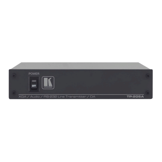
12V DC 1 Using a UTP CAT5 cable with RJ-45 connectors at both ends (the PINOUT is defined in Table 3 and Figure 5) 2 For example, the Kramer TP-124, the Kramer TP-46, and so on Your TP-205A Figure 1: TP-205A... -
Page 8: The Tp-205A Underside
4.1.1 The TP-205A Underside Figure 2 and Table 2 define the underside of the TP-205A Table 2: Features of the TP-205A Underside Feature HS Switch Slide the switch up, to set the H SYNC to negative polarity (NEGATIVE) Slide the switch down, to set the H SYNC to its input polarity (NORMAL) -
Page 9: Configuring The Tp-205A
3 If the digital audio input is selected, release the SELECT button 4 The two right pins (GND and LOOP) can be connected to the GND and IN connectors on an additional TP-205A unit 5 As defined in Figure 6 and Table 4 (see section 5.4) 6 You do not have to connect all the outputs 7 Refer to the separate user manual, which can be downloaded from the Internet at http://www.kramerelectronics.com... -
Page 10: Figure 3: Connecting The Xga / Audio / Data Line Transmitter / Receiver System
Figure 3: Connecting the XGA / Audio / Data Line Transmitter / Receiver System 1 By default, both switches are set down (for normal V SYNC and H SYNC polarity) Configuring the TP-205A KRAMER: SIMPLE CREATIVE TECHNOLOGY on the underside. -
Page 11: Looping The Tp-205A
TP-120 TP-122 1 The number of TP-205A units that can be looped depends upon the quality of the input signal that you require and the distance between the machines. We do not recommend cascading more than five TP-205A units Configuring the TP-205A... -
Page 12: Wiring The Cat5 Line In / Line Out Rj-45 Connectors
Pair 2 1 and 2 Pair 3 3 and 6 Pair 4 7 and 8 PC (Controller) to TP-205A Connector PIN: Figure 5: CAT5 PINOUT PIN 5 Connected to GND PIN 3 Connected to RxD To PC (DB9F) Figure 6: RS-232 PINOUT... -
Page 13: Technical Specifications
Technical Specifications Table 5 includes the technical specifications of the TP-205A: Table 5: Technical Specifications of the TP-205A INPUTS: VIDEO: 1 VGA / UXGA on an HD15 connector AUDIO: 1 audio ANALOG 3.5mm mini jack, 1 audio S/PDIF RCA connector... - Page 14 EXCLUSION OF DAMAGES The liability of Kramer for any effective products is limited to the repair or replacement of the product at our option. Kramer shall not be liable for: 1. Damage to other property caused by defects in this product, damages based upon inconvenience, loss of use of the product, loss of time, commercial loss;...
- Page 15 For the latest information on our products and a list of Kramer distributors, visit our Web site: www.kramerelectronics.com, where updates to this user manual may be found. We welcome your questions, comments and feedback. Safety Warning: Disconnect the unit from the power supply before opening/servicing.
Need help?
Do you have a question about the TP-205A and is the answer not in the manual?
Questions and answers