Table of Contents
Advertisement
Quick Links
Advertisement
Table of Contents

Subscribe to Our Youtube Channel
Summary of Contents for Kramer TA
- Page 1 Kramer Electronics, Ltd. USER MANUAL Model: Cobra TA Video / Audio Transmitter...
-
Page 2: Table Of Contents
Figure 1: Connecting the Cobra TA Video / Audio Transmitter Figure 2: Connecting the Cobra Receiver Figure 3: Transmitter to Receiver Connections Tables Table 1: Technical Specifications of the Cobra TA Video / Audio Transmitter Table 2: HD15 PINOUT Contents... -
Page 3: Introduction
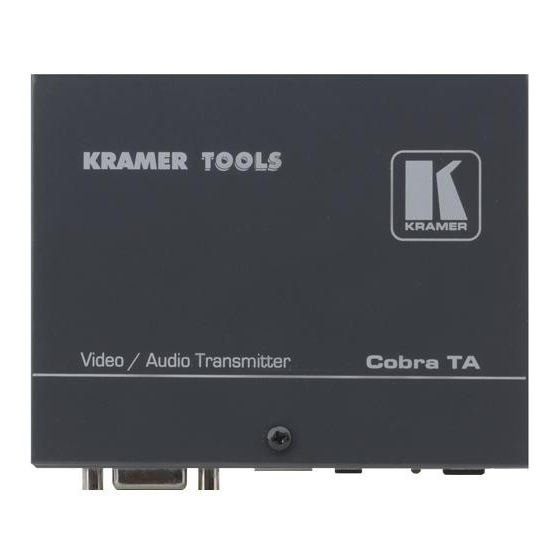
Congratulations on purchasing your Kramer TOOLS Cobra TA Video / Audio Transmitter, which extends VGA and audio signals over ordinary CAT5e cable. The package includes the Cobra TA Video / Audio Transmitter and this user manual Getting Started We recommend that you:... - Page 4 (often associated with low quality cables) Avoiding interference from neighboring electrical appliances that may adversely influence signal quality and positioning your Cobra TA in a location free from moisture and away from excessive sunlight and dust Caution...
-
Page 5: Setup And Installation
At the transmitter end: 1. Connect the source video to the Cobra TA Series transmitter video input port, which is an HD15 connector labeled VIDEO INPUT. 2. Make your audio connections via the 1/8” (3.5mm) audio connector. -
Page 6: Connecting The Cobra Ta Video / Audio Transmitter
4.2 Connecting the Cobra TA Video / Audio Transmitter The Cobra TA Video / Audio Transmitter supports video and audio signals over CAT5 cable. The audio signal is line-level audio, and powered speakers are required. Figure 1 shows the Cobra TA Video / Audio Transmitter connections, and Figure 2 shows a typical Cobra receiver connection. -
Page 7: Typical Single-Port Transmitter-Receiver Application
Setup and Installation 4.3 Typical Single-Port Transmitter–Receiver Application Figure 3 shows a typical application in which the Cobra TA Video / Audio Transmitter is connected over CAT5 to a receiver. Figure 3: Transmitter to Receiver Connections... -
Page 8: Solutions To Common Problems
Solutions to Common Problems There are no user configurable settings on the Cobra TA Video / Audio Transmitter. In most cases, nearly every issue with the Cobra Series can be resolved by checking the CAT5 termination and making sure that it is pinned to the 568B wiring specification. -
Page 9: Technical Specifications
WEIGHT: 1 Specifications are subject to change without notice Technical Specifications of the Cobra TA Video / Audio Transmitter Category 5, 5e, 6 shielded or unshielded twisted pair CE; FCC Class A, IC Class/class A RGBHV, RGB, Composite, S-Video, Component Video modes To 1920x1200 @ 60Hz (receiver dependent) Video OUT: 75 ohms;... -
Page 10: Table 2: Hd15 Pinout
V Sync — Technical Specifications Table 2: HD15 PINOUT RGsB Composite SVHS (Y/C) Red + Green+ Blue+ — Red- Green- Blue- — — — — — — — KRAMER: SIMPLE CREATIVE TECHNOLOGY Composite Video and Stereo Audio Audio Audio Shield Shield... - Page 11 Technical Specifications...
- Page 12 KRAMER: SIMPLE CREATIVE TECHNOLOGY...
- Page 13 For the latest information on our products and a list of Kramer distributors, visit our Web site: www.kramerelectronics.com, where updates to this user manual may be found. We welcome your questions, comments and feedback. Safety Warning: Disconnect the unit from the power supply before opening/servicing.


Need help?
Do you have a question about the TA and is the answer not in the manual?
Questions and answers