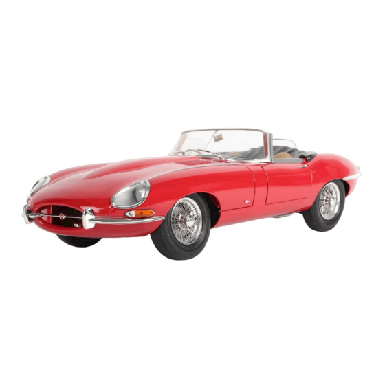
Agora Models JAGUAR E-TYPE Build Instructions
Hide thumbs
Also See for JAGUAR E-TYPE:
- Build instructions (60 pages) ,
- Build instructions (35 pages) ,
- Build instructions (55 pages)
Advertisement
Quick Links
Pack 06
B U I L D
I N S T R U C T I O N S
STAGE 41: RIGHT FRONT WHEEL
STAGE 46: REAR SUBFRAME
LEFT SUSPENSION
STAGE 42: FRONT FLOOR PANEL
STAGE 47: REAR SUBFRAME
STAGE 43: FLOOR PANEL ASSEMBLY
RIGHT SUSPENSION
STAGE 44: FINAL DRIVE UNIT
STAGE 48: INSTALLING THE
REAR SUBFRAME
STAGE 45: REAR SUBFRAME
Advertisement

Subscribe to Our Youtube Channel
Related Manuals for Agora Models JAGUAR E-TYPE


Summary of Contents for Agora Models JAGUAR E-TYPE
- Page 1 Pack 06 B U I L D I N S T R U C T I O N S STAGE 41: RIGHT FRONT WHEEL STAGE 46: REAR SUBFRAME LEFT SUSPENSION STAGE 42: FRONT FLOOR PANEL STAGE 47: REAR SUBFRAME STAGE 43: FLOOR PANEL ASSEMBLY RIGHT SUSPENSION STAGE 44: FINAL DRIVE UNIT STAGE 48: INSTALLING THE...
- Page 2 WARNING: Some parts are assembled using magnets. These magnets can cause serious injury if they are swallowed. Keep away from children. If you suspect a magnet has been swallowed, seek medical help straight away. AGORAMODELS JAGUAR E-TYPE...
- Page 3 In this stage you’ll fix the right front wheel to the subframe. S T A G E 4 1 P A R T S L I S T Name Tyre Washer Screws type AM07 x2 Tyre AM07 x2 Washer AGORAMODELS JAGUAR E-TYPE...
- Page 4 Working quickly while the tyre is pliable, push the wheel into the tyre Keep pushing and pulling, working around the tyre, until the side walls and twist to fit the outer wheel rim under the inner rim of the tyre. fit comfortably over the wheel rim on both sides. AGORAMODELS JAGUAR E-TYPE...
- Page 5 Position the wheel in place, ensuring the lugs fit into the notches. Take the washer and drop it onto the end of the stub axle, as shown in picture 8. AGORAMODELS JAGUAR E-TYPE...
- Page 6 Stage 41: Right Front Wheel AM07 Secure the washer and right wheel in place using a type AM07 screw. S T A G E C O M P L E T E AGORAMODELS JAGUAR E-TYPE...
- Page 7 There is no assembly in this Stage, unpack the front floor panel and move straight to Stage 43. S T A G E 4 2 P A R T S L I S T Name Front floor panel Front floor panel AGORAMODELS JAGUAR E-TYPE...
- Page 8 S T A G E 4 3 P A R T S L I S T Name Rear floor panel Screws type AG06 x5 Rear floor panel AG06 x5 AGORAMODELS JAGUAR E-TYPE...
- Page 9 Fit the rear panel onto the front panel. up the four screw holes on the rear panel with the protruding holes on the front panel as shown. AG06 AG06 Screw the parts together using 4x type AG06 screws. AGORAMODELS JAGUAR E-TYPE...
- Page 10 Stage 43: Floor Panel Assembly S T A G E C O M P L E T E AGORAMODELS JAGUAR E-TYPE...
- Page 11 Universal joint (right-hand) Lower casing Bonnet catch plate Screws typr AG06 x4 Screws type AG02 x2 Rear brake Rear brake (left-hand) (right-hand) AG06 x4 Universal joint Universal joint Upper casing (left-hand) (right-hand) AG02 x2 Lower casing Bonnet catch plate AGORAMODELS JAGUAR E-TYPE...
- Page 12 Match up the left rear brake with the left universal joint by locating the ‘L’ on the parts (inset). Do the same for the right rear brake and joint by locating the ‘R’. AGORAMODELS JAGUAR E-TYPE...
- Page 13 Take the left universal joint and align it with the slot in the left rear Fit the universal joint into the rear brake. brake as shown. AG06 Then fit the universal joint and brake assembly onto the lower casing Secure in place using a type AG06 screw. as shown. AGORAMODELS JAGUAR E-TYPE...
- Page 14 Stage 44: Final Drive Unit Take the right universal joint and fit into the right rear brake. AG06 Fit into the lower casing as shown. Fix in place with a type AG06 screw. AGORAMODELS JAGUAR E-TYPE...
- Page 15 (arrows). flush all the way around. AG06 Fit a type AG06 screw through the hole in the top of the casing to fix the two halves together. AGORAMODELS JAGUAR E-TYPE...
- Page 16 Stage 44: Final Drive Unit S T A G E C O M P L E T E AGORAMODELS JAGUAR E-TYPE...
- Page 17 S T A G E 4 5 P A R T S L I S T Name Rear subframe Handbrake linkage Screws type AG04 x2 Screws type AG06 x2 Screws type AM18 x3 Rear subframe Handbrake linkage AG04 x2 AG06 x2 AM18 x3 AGORAMODELS JAGUAR E-TYPE...
- Page 18 1. assembly with 1 x type AG04 screw and 1 x type AG06 screw. Note: be aware two different screws are used. Make sure to screw the correct type in place to avoid damaging the threads. AGORAMODELS JAGUAR E-TYPE...
- Page 19 (arrow). AM18 Once in place the handbrake linkage should look like this. Screw both of the arms to the subframe using 2 x AM18 type screws. AGORAMODELS JAGUAR E-TYPE...
- Page 20 Stage 45: Rear Subframe S T A G E C O M P L E T E AGORAMODELS JAGUAR E-TYPE...
- Page 21 Screws type AM16 x3 AG04 x2 AG05 x3 AG06 x2 AM16 x3 Long spindle Shock absorber Coil springs x2 Universal joint Mounting plate Shock absorber bodies pistons x2 Medium spindle Left-hand wishbone Left-hand halfshaft Hub carrier Short spindles x3 AGORAMODELS JAGUAR E-TYPE...
- Page 22 Holding the shock absorber together, take a type AG05 screw and spring into the shock absorber body, ensuring the piston shaft is insert it into the end of the shaft of the shock absorber body. inserted into the cylinder of the shock absorber body. AGORAMODELS JAGUAR E-TYPE...
- Page 23 Take the remaining coil spring and fit it onto the opposite shock Take the other shock absorber piston and attach to the body with a absorber body. type AG05 screw, repeating the steps shown in pictures 4 and 5. AGORAMODELS JAGUAR E-TYPE...
- Page 24 Place the shock absorber into the subframe as shown, so that the bar Take the mounting plate and align it so that the shorter end is on the shock absorber (arrow) is between the two holes on the base of pointing inwards towards the drive unit. the subframe. AGORAMODELS JAGUAR E-TYPE...
- Page 25 (circled) in the centre. end and a ribbed end (arrow). Ensure that the holes in the universal joint align with the holes on the end of the halfshaft. AGORAMODELS JAGUAR E-TYPE...
- Page 26 Take another short spindle, gripping the ribbed end with pliers or Using the opening on the side of the subframe, fit the smooth end of tweezers as shown. Hold the halfshaft in place. the spindle into the halfshaft and universal joint. AGORAMODELS JAGUAR E-TYPE...
- Page 27 Take the wishbone and align it with the rear subframe assembly as Ease the wishbone into the two eyes of the shock absorber pistons. shown. Note one of the pivots is slightly larger than the other, and there is a lug on one side of the shaft (arrows). AGORAMODELS JAGUAR E-TYPE...
- Page 28 Take the remaining short spindle and align it so the ribbed end is Push the spindle into the subframe and through the pivot of the facing outward. wishbone. Squeeze the spindle into place until it fits flush with the subframe. AGORAMODELS JAGUAR E-TYPE...
- Page 29 Take the hub carrier and align it with the free end of the wishbone the holes of the rear subframe and wishbone pivot. Squeeze the as shown. spindle with pliers until it fits flush. Position the hub carrier in the wishbone ensuring that the small holes are aligned. AGORAMODELS JAGUAR E-TYPE...
- Page 30 Stage 46: Rear Subframe Left Suspension Holding the hub carrier in place, push the smooth end of the long spindle through the wishbone/hub carrier joint. Squeeze the spindle into place until it sits flush. AGORAMODELS JAGUAR E-TYPE...
- Page 31 AM16 Insert a type AM16 screw into the eye of the shock absorber piston. Repeat on the opposite side with another type AM16 screw. S T A G E C O M P L E T E AGORAMODELS JAGUAR E-TYPE...
- Page 32 Screws type AM16 x3 AG04 x2 AG05 x3 AM16 x3 Long spindle AG06 x2 Shock absorber Coil springs x2 Universal joint Mounting plate Shock absorber bodies pistons x2 Medium spindle Right-hand wishbone Right-hand halfshaft Hub carrier Short spindles x3 AGORAMODELS JAGUAR E-TYPE...
- Page 33 Holding the shock absorber together, take a type AG05 screw and spring into the shock absorber body, ensuring the piston shaft is insert it into the end of the shaft of the shock absorber body. inserted into the cylinder of the shock absorber body. AGORAMODELS JAGUAR E-TYPE...
- Page 34 Take the remaining coil spring and fit it onto the opposite shock Take the other shock absorber piston and attach to the body with a absorber body. type AG05 screw, repeating the steps shown in pictures 4 and 5. AGORAMODELS JAGUAR E-TYPE...
- Page 35 Place the shock absorber into the subframe as shown, so that the bar Take the mounting plate and align it so that the shorter end is on the shock absorber is between the two holes on the base of the pointing inwards towards the drive unit. subframe. AGORAMODELS JAGUAR E-TYPE...
- Page 36 (circled) in the centre. end and a ribbed end (arrow). Ensure that the holes in the universal joint align with the holes on the end of the halfshaft. AGORAMODELS JAGUAR E-TYPE...
- Page 37 Fit the halfshaft so that the holes align with the holes of the universal Take a short spindle, gripping the ribbed end with pliers or tweezers as joint of the final drive unit (arrows). shown. Hold the halfshaft in place. AGORAMODELS JAGUAR E-TYPE...
- Page 38 The halfshaft should look like this once in place. Take the wishbone and align it with the assembly as shown. Note one of the pivots is slightly longer than the other, and there is a lug on one side of the shaft (arrows). AGORAMODELS JAGUAR E-TYPE...
- Page 39 Ease the wishbone into the two eyes of the shock absorber pistons (arrows). facing outward. Push the smooth end into the subframe and through the wishbone pivot. Squeeze the spindle into place. Take the medium spindle and push the smooth end into the subframe and wishbone pivot. AGORAMODELS JAGUAR E-TYPE...
- Page 40 The second wishbone has now been fitted. Position the hub carrier in the wishbone ensuring that the small holes Holding the hub carrier in place, push the smooth end of the long are aligned. spindle through the wishbone and hub carrier joint. AGORAMODELS JAGUAR E-TYPE...
- Page 41 Squeeze the spindle into place until it sits flush. Insert a type AM16 screw into the eye of the shock absorber piston. AM16 Repeat on the opposite side to secure the other piston with another type AM16 screw. AGORAMODELS JAGUAR E-TYPE...
- Page 42 Stage 47: Rear Subframe Right Suspension S T A G E C O M P L E T E AGORAMODELS JAGUAR E-TYPE...
- Page 43 Links x2 Screws type AM01 x5 Screws type AG06 x9 Screws type AM17 x3 AM17 x3 AM01 x5 AG06 x9 Radius arms (left and right) Safety straps x2 Bracing plate Links x2 Rear anti-roll bar Mounting brackets x2 AGORAMODELS JAGUAR E-TYPE...
- Page 44 Take the other link and repeat for the other side. The bar should look Take the radius arms and identify the left arm from the right arm like this, with both lugs facing inwards. using the ‘L’ and ‘R’ on the parts (circled). AGORAMODELS JAGUAR E-TYPE...
- Page 45 Take one of the mounting brackets and fit it over the anti-roll bar, and arms as shown, so the arch of the bar is pointing upwards. Rest aligning it with the mounting holes. the bar on the underside of the floor, between the pairs of mounting holes (arrows). AGORAMODELS JAGUAR E-TYPE...
- Page 46 Secure the bracket with 2 x type AG06 screws. AG06 Repeat to secure the bracket on the other side using another 2 x AG06 Flip the arms so that they rest on the underside of the floor as shown. screws. AGORAMODELS JAGUAR E-TYPE...
- Page 47 Take the rear subframe from Stage 47 and align it with the floor assembly as shown. The universal joint will fit under the arched section of the anti-roll bar (arrow). Fit the subframe into the floor assembly so that the flat surface of the subframe sits flush and the screw holes align (see picture 15). AGORAMODELS JAGUAR E-TYPE...
- Page 48 Check that the holes on the opposite ends of the radius arms align Push the pins on both the radius arms into the holes on both the wishbones (see also circled in picture 18). with the screw holes in the floor (arrows). AGORAMODELS JAGUAR E-TYPE...
- Page 49 In the orientation shown, fit one end of one of the safety straps Holding the safety strap in place, flip the assembly over. Locate the through the hole in the radius arm and the other end into the two indicated holes on the reverse side (arrows). floor panel. AGORAMODELS JAGUAR E-TYPE...
- Page 50 Turn the assembly over and fit the remaining safety strap to the other radius arm. AG06 Holding the safety strap in place, turn the assembly over once again and secure in place with another 2 x type AG06 screws. AGORAMODELS JAGUAR E-TYPE...
- Page 51 Stage 48: Installing the Rear Subframe S T A G E C O M P L E T E AGORAMODELS JAGUAR E-TYPE...
Need help?
Do you have a question about the JAGUAR E-TYPE and is the answer not in the manual?
Questions and answers