Table of Contents
Advertisement
Quick Links
Advertisement
Table of Contents

Related Manuals for Air Techniques Rxonly ProVecta 3D Prime


Summary of Contents for Air Techniques Rxonly ProVecta 3D Prime
- Page 1 ProVecta 3D Prime Operating instructions 2210200496L41 *2210200496L41* A7766...
- Page 3 Contents Contents Exposure button ... . . Memory card slot ... . Sensor window ....Important information About this document .
-
Page 4: Table Of Contents
Contents 10.1 Recommended maintenance schedule ....Troubleshooting 11 Tips for operators and service techni- cians ......Appendix 12 Program parameters . - Page 5 These installation and operating instructions are an integral part of the unit. – CAUTION Risk of minor injuries Air Techniques shall not be held liable and – NOTICE offers no guarantees of the safe and Risk of extensive material/property damage...
- Page 6 Printing or copying these Installation and Operat- ing Instructions, including excerpts thereof, may Stacking limits only be carried out with the written approval of Air Techniques. Recycling Keep dry This way up / store and transport in an upright position Keep away from sunlight during storage Refer to Operating Instructions.
- Page 7 Important information Safety General safety information Comply with the guidelines, laws, rules and ❯ The unit has been developed and designed regulations applicable at the site of operation appropriately such that hazards are largely when you use this unit. excluded if the unit is used in accordance with its Prior to each use, check the function and Normal Use.
- Page 8 All installation, resetting, alteration, expansion, ❯ reduced electromagnetic immunity, and repair work must be carried out either by leading to an erroneous operation Air Techniques personnel or by a suitably quali- mode. fied person approved by Air Techniques. NOTICE Protection from electric...
- Page 9 2.11 Only use genuine parts 2.14 Protection from cybersecurity threats Only Air Techniques accessories and special ❯ accessories or those approved by Air Techni- The unit is to be connected to a computer that ques may be used. can be connected to the Internet. Therefore, the Only use original spare and replacement parts.
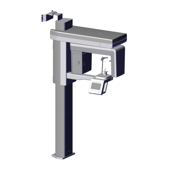
- Page 10 Product description Product description Overview 14 13 3D and panoramic X-ray unit Head supports with cushion Wall bracket Hygienic protective covers for bite block Frame grabber card 10 Bite block USB dongle 11 Adapter for bite block USB stick with device-specific calibration 12 Chin holder for maxillary joint image data 13 Chin holder for edentulous jaws...
- Page 11 Product description Consumables Scope of delivery The following materials are consumed during The following items are included in the scope of operation of the device and must be re-ordered: delivery (possible variations due to country-spe- Hygienic protective cover bite block (100 cific requirements and/or import regulations): pieces) .
- Page 12 Maximum power Fuses* (2 pcs.) T 10.0 AH / 250 V~ (IEC 60127-2, Sheet * The fuses may only be replaced by Air Techniques or by a body authorized by Air Techniques. Classification Medical device of class FDA classification (CFR Title 21)
- Page 13 Product description X-ray emitter Nominal voltage, high-voltage generator 50 - 99 (±10 %) Nominal current, high voltage generator 4 - 16 (± 10%, max. 75 kV 16 mA, max. 99 kV 10 mA) Cooling, high-voltage generator Automatic monitoring Shut-off at ≥ 60°C Additional filtering at 50 kV 2.0 + 3.0 (added automatically for CBCT) mm Al...
- Page 14 Product description Maximum Rating Charts DC (Center Grounded) Constant potential high-voltage generator Nominal Focus Spot Value: 0.5 70kV 80kV 60kV 90kV 50kV 100kV EXPOSURE TIME [s] Emission and Filament Characteristics Constant potential high-voltage generator Nominal Focus Spot Value: 0.5 80kV 100kV 50kV FILAMENT CURRENT [A]...
- Page 15 Product description Anode Thermal Characteristics 175 W COOLING HEATING TIME (min) Detector Pano/CBCT Brand Xmaru1404CF Type CMOS photodiode array Pixel size μm 49.5 99 (2x2 binning) 198 (4x4 binning) 0.001949 0.003898 (2x2 binning) 0.007795 (4x4 binning) Sensor size 230 x 160 x 26 9.06 x 6.30 x 1.02 Active surface area 135.8 x 36.4...
- Page 16 Product description Electromagnetic compatibility (EMC) Interference emission measurements High-frequency emissions in accordance with CISPR 11 Group 1 Interference voltage at the power supply connection Class A CISPR 11:2009+A1:2010 Electromagnetic interference radiation Class A CISPR 11:2009+A1:2010 Emission of harmonics Class A IEC 61000-3-2:2005+A1:2008+A2:2009 Voltage changes, voltage fluctuations, and emission of Conforms...
- Page 17 Product description Immunity to interference levels by near fields of wireless HF communication devices Radio service Frequency band Test level GSM 1800 CDMA 1900 GSM 1900 1700 - 1990 DECT LTE bands 1, 3, 4, 25 UMTS Bluetooth WLAN 802.11 b/g/n 2400 - 2570 RFID 2450 LTE band 7...
- Page 18 Product description Dimensions 572,5 mm 22,54 in 1212 mm 47,72 in 2210200496L41 1911V006...
- Page 19 Product description Model identification plate Type plate of the unit Type plate of the X-ray tube Conformity assessment This device has been subjected to conformity acceptance testing in accordance with the cur- rent relevant guidelines of the European Union. This equipment conforms to all relevant require- ments.
- Page 20 Product description Function Operating elements Touch screen Emergency stop switch Button for opening/closing the head sup- On/off switch ports X-ray tube Button for positioning beams on/off C-shaped elbow Buttons for height adjustment Status LED The touch screen can be used to operate the Operating elements unit.
- Page 21 Product description Status LED Lever for positioning the upper canine posi- tioning beam Mid-sagittal positioning beam Grips The applied parts in accordance with IEC 60601-1 are: – Grips – Head supports with cushion – Positioning aids (e.g. bite block and mounting for bite block, chin support for edentulous patients) Description of the positioning aids...
- Page 22 Product description Exposure button Sensor window The active sensor surface is indicated by the Exposure switch markers in the corners of the sensor window. The exposure switch is used to trigger the pre- The cross indicates the geometric mid-point of pared image acquisition and start the X-ray expo- the active sensor surface.
- Page 23 Usage Using menus Usage The menus integrated in a window contain addi- tional commands that can be selected. To open the menu, tap ❯ Operating the touch screen NOTICE Damage to the touch screen due to incorrect handling Only touch the touch screen with your ❯...
- Page 24 Usage Operation Use the main power switch to switch the unit ❯ CAUTION Health risks for the patient due to contraindications Before using the unit on the patient, ❯ make sure that none of the listed con- traindications are evident. In this section, the term "Child"...
- Page 25 Usage Children are more sensitive to radiation Image volume "Normal" than adults. Keep the exposure parame- Size (W x H): approx. 100 x 85 ters as low as possible taking into consid- eration the image quality. Refer also to Image volume "Child" the FDA information on pediatric X-ray Size (W x H): approx.
- Page 26 Usage Narrow jaw arch Wide jaw arch Child's jaw arch 2210200496L41 1911V006...
- Page 27 Usage Image acquisition programs CBCT images CBCT The CBCT image shows the jaw area. The size of the jaw area shown depends on the selected image volume. Resolution: 200 μm CBCT 5x5 Maxilla Molar right The X-ray image depicts the right molar region of the maxilla with a volume of 5x5 cm.
- Page 28 Usage Panoramic images Standard The standard panoramic image records the com- plete dental area with ascending dental branches and maxillary joints. Front The image shows a reduced dental area without ascending dental branches. Right The image only shows the right dental area. Left The image only shows the left dental area.
- Page 29 Usage Panoramic images Bite wing right The image shows the right posterior region with a size limited to the bite wings. Bite wing left The image shows the left posterior region with a size limited to the bite wings. Temporomandibular imaging Maxillary joint, lateral The image shows the lateral maxillary joints for an open and closed mouth in 4-fold depiction in one...
- Page 30 Usage Sinus images Sinus, PA The X-ray image shows the posterior-anterior sinuses. 2210200496L41 1911V006...
- Page 31 Usage Inserting the cushions of the head supports Inserting the positioning aids If no cushions are inserted in the head supports For the acquisition of the X-ray image, the patient or if they are dirty, insert new cushions before is positioned in the unit using the corresponding you position the patient.
- Page 32 Usage Inserting the positioning aid for CBCT images The bite block can be used with or with- We recommend using the holder for bite block out a hygienic protective cover. on CBCT images. The bite block can be used We recommend using the bite block with optionally in addition to this.
- Page 33 Usage In the case of edentulous patients, the chin ❯ WARNING support for edentulous jaws can be used. There is a danger of cross contamina- tion if hygienic protective covers are not used or if they are re-used Reprocess the bite block after using it ❯...
- Page 34 Usage Inserting the positioning aid for panoramic Inserting the positioning aid for the maxillary images with hygienic protective cover (optional) joint image Correct image acquisition is only possible with WARNING the chin support for maxillary joint images. Risk of cross contamination due to Inserting the chin support for the maxillary joint ❯...
- Page 35 Usage Opening the head supports CAUTION Danger of injury by moving rotating unit arm After the unit is switched on and the parameters are confirmed on the touch screen, the C-shaped angle connector piece is positioned. Persons can be injured during this. Nobody may be present in the area of ❯...
- Page 36 Usage CBCT image acquisition Sinus image acquisition The patient is positioned as follows depending on Position the patient so that his/her bottom lip ❯ the indication: presses lightly against the chin support. The patient bites onto the bite block, with the ❯...
- Page 37 Usage Check the X-ray positioning beam for the mid- Correct any inclination of the head via the ❯ ❯ sagittal plane and correct the position of the height of the unit. patient if necessary. If necessary, correct the X-ray positioning beam manually.
- Page 38 Usage If necessary, correct the X-ray positioning Close the head supports with the button. ❯ ❯ beam manually. To do this, just press the button briefly – don't press and hold. The head supports automatically touch against the head of the patient at a defined pressure. Once the patient has been correctly positioned ❯...
- Page 39 Usage Taking the X-ray image Press Start to confirm the parameters. ❯ The rotating unit is being positioned. The LED on the exposure switch and the status LED on CAUTION the unit light up green. Injuries due to X-rays The touch screen displays that the unit is ready X-rays can cause tissue damage.
- Page 40 Usage the unit is damaged. It can also be used to avert an unwanted collision. The yellow stickers on the patient positioning system with the symbol show the location of the emergency stop switch. After the acquisition of maxillary joint images, it is necessary to confirm a message on the touch screen and trig- ger a second image acquisition.
- Page 41 Usage Press the emergency stop switch. ❯ The unit automatically restarts. Device is switched off. Releasing the emergency stop switch CAUTION Danger of injury by moving rotating unit arm After the unit is switched on and the parameters are confirmed on the touch screen, the C-shaped angle connector piece is positioned.
- Page 42 Usage Cleaning and disinfection Remove any soiling with a soft, damp, lint-free ❯ cloth. Disinfect the surfaces with a disinfection wipe. ❯ NOTICE Alternatively, use a quick-acting surface disin- The use of unsuitable agents and fectant on a soft, lint-free cloth. Comply with methods can damage the unit and the operating instructions of the disinfectant.
- Page 43 Usage Disinfect the surfaces using a disinfection wipe. ❯ Alternatively, use a quick-acting surface disin- fectant on a soft, lint-free cloth. Comply with the operating instructions of the disinfectant. Reprocessing the cushions (see "9 Reprocess- ❯ ing"). 2210200496L41 1911V006...
- Page 44 Usage Reprocessing Reprocessing procedure in accordance with EN ISO The following accessories need to be reproc- 17664 essed: – Bite block: Perform the reprocessing procedure after each – Manual cleaning patient treatment and according to the reproc- – Automatic cleaning and disinfection essing procedure established by EN ISO 17664.
- Page 45 Usage The reprocessing procedure was validated as fol- Only use distilled or de-ionized water with a low ❯ lows: bacterial count (at least drinking water quality) – Pre-cleaning: that is free from facultatively pathogenic micro- – Monarch surface disinfection wipes (Air organisms (e.g.
- Page 46 Usage Check for function Comply with the exposure times of the cleaning ❯ agent. After the end of the cleaning and disinfection ❯ cycle, check the components for any residual Intermediate rinsing soiling and residual moisture. If necessary, After the action time prescribed by the manufac- repeat the cycle.
- Page 47 Usage Perform the following steps: Sterilize the parts for sterilization (at least 20 ❯ minutes at 250°F, at least 4 minutes at 270°F or at least 5 minutes at 274°F). Do not exceed 281 °F. Marking Mark the packaged, treated medical device ❯...
- Page 48 10 Maintenance 10.1 Recommended maintenance schedule Only qualified personnel or personnel trained by Air Techniques is allowed to service the unit. DANGER Risk of electric shock due to live parts Install an all-pole disconnect switch with a contact opening width of at least 3 mm in the elec- ❯...
- Page 49 Usage Maintenance Maintenance work interval Every 3 years ❯ Visually and acoustically check the linear movement on the rotating unit. ❯ Check the operation of the lift motor. Does the unit lift and lower with minimal noise? 2210200496L41 1911V006...
-
Page 50: Troubleshooting
Troubleshooting Troubleshooting CAUTION Any oil leaking from the X-ray tube in the event of a fault is harmful. Wipe up any oil immediately. ❯ Do not swallow the oil. ❯ Stop using the unit and inform a service technician. ❯ 11 Tips for operators and service technicians Any repairs above and beyond routine maintenance may only be done by suitably qualified per- sonnel or by one of our service technicians. - Page 51 Troubleshooting Error Possible cause Remedy Error messages during start of Energy-saving options incor- ❯ Deactivate the energy-saving the acquisition of an X-ray rectly configured options in Windows and the image or during shut down of BIOS completely. the PC Supply voltage for graphic card ❯...
-
Page 52: Appendix
Appendix Appendix 12 Program parameters The digital extraoral dental X-ray system meets the requirements set out in standard IEC 60601-2-63. The dosage information complies with the requirements of the standard and is stated in mGy. The accuracy of the DAP/dose values is ± 50%. 12.1 CBCT program parameters CBCT image acquisition, normal image volume, 16.4 s... - Page 53 Appendix 12.5 mA 14.0 mA mGycm mGycm 17.27 108.81 19.38 122.11 74 kV 80 kV 19.76 124.46 22.17 139.68 2210200496L41 1911V006...
-
Page 54: Information On Scattered Radiation
Appendix 1.5 m 13 Information on scattered ° mR/h mR/h mR/h radiation 76.4 19.4 13.1 CBCT scattered radiation Test equipment: Dosimeter Radcal 9015 Test conditions Program parameters CBCT Image acquisition vol- Normal Voltage 99 kVp Current 14 mA 1.5 m °... -
Page 55: Information On The Leakage Rate
Appendix 14 Information on the leak- Direction HD, Adult, HD, Child, 13.5 s 11.5 s age rate ° Test equipment: Dosimeter Victoreen 660 6.2 mR/h 2.4 mR/h Test conditions 1.2 mR/h 6.6 mR/h Program parameters HD / Adult, child / 1.6 mR/h 4 mR/h Standard Pano... - Page 60 For over 50 years, Air Techniques has been a leading innovator and manufacturer of dental products. Our priority is ensuring complete satisfaction by manufacturing reliable products and providing excel- lent customer and technical support. Whether the need is digital imaging, utility room equipment or merchandise, Air Techniques can provide the solution via our network of authorized professional deal- ers.
Need help?
Do you have a question about the Rxonly ProVecta 3D Prime and is the answer not in the manual?
Questions and answers