Table of Contents
Advertisement
Advertisement
Table of Contents

Related Manuals for Air Techniques MOJAVE LT3


Summary of Contents for Air Techniques MOJAVE LT3
- Page 1 Dry Vacuum System U s er’s an d Instal lation Manua l...
-
Page 2: Table Of Contents
MOJAVE LT3 Front Panel Controls and Indicators . . . . . . . . . . . . . . . . . -
Page 3: Congratulations
. With this balanced system, each user always has the flow rate necessary to do the job while conserving electricity and prolonging the life of your pump . SAFETY SUMMARY Use of the MOJAVE LT3 not in conformance with the instructions specified in this manual may result in permanent failure of the unit . WARNING: To prevent fire or electrical shock, do not expose this equipment to rain in or moisture. -
Page 4: Sizing Guide
To ensure optimum operation, the demands should not exceed the number of vacuum users shown below . The chart lists the number of simultaneous High Volume Evacuators (HVEs) and Saliva Ejectors (SEs) that can be used by the MOJAVE LT3 system . Recommended Number of Simultaneous HVE/SE Users Note: 1 HVE = 2 SE’s... -
Page 5: Product Description
An aluminum heat exchanger to cool the exhaust air from the pump before it travels through the exhaust vent . The LCD touch screen provides the operational user interface for the MOJAVE LT3 system . Electrical Sight Glass... -
Page 6: Mojave Lt3 Functional Connection Points
3 . Liquids and solids exit through the drain line of the separator . 4 . The LCD touch screen provides the operational user interface for the MOJAVE LT3 system . It monitors and displays the frequency, vacuum level, RPM reading and temperature as well as recording the run time in hours . -
Page 7: Installation Information
The suction line should not have any sharp right angle bends and must be sloped a minimum ¼ inch for every 10 feet toward the MOJAVE LT3 . The drain on the base of the air/water separator must be connected to a vented or an open floor drain capable of handling 5 gallons in 1 minute . - Page 8 2. Use maximum internal diameter for the main line when preparing any new installation. Recommended Space Requirement Unit Dimensions: Height 20 in . (51 cm) Width 24 in . (61 cm) Depth 16 .5 in . (42 cm) Page 8 Air Techniques, Inc.
-
Page 9: Mojave Lt3 System Floor Plan
MOJAVE LT3 . Schedule 40 pipe can be used on MOJAVE LT3. PUMP ELECTRIC SERVICE - The MOJAVE LT3 pump is wired directly with a dedicated 220V, 20 AMP , single phase 50/60 Hz circuit . If Main Circuit panel is not located in equipment room, a disconnect box with approved ground is needed for each pump . -
Page 10: Installation
Since the vacuum hose is rigid, make sure not to stress connections especially at the pump inlet. MOJAVE LT3 Connection Procedure. Using industry standard techniques, make the three connections between the LT3 with supplied components from accessory kits Refer to Figure 5 for the connection diagram and perform the following procedure . -
Page 11: Mojave Lt3 Detail Plumbing Connection
Drip Leg and Flex Tubing Exhaust Vent Assembly 1/4-inch Vent Condensation Drain Port 1" Drain Hose Open Drain Pipe Clamp Connection to Facility Sewer Closed Vented Drain Drain Figure 6. MOJAVE LT3 Detail Plumbing Connection Air Techniques, Inc. Page 11... -
Page 12: Electrical Connections
Make the 6 VDC connections shown by Figure 9, View A, for Remote Panel Switch #53202-1 pro- vided by Air Techniques . Make the 24 VDC connections shown by Figure 9, View B, for Remote Panel Switch #53201-1 . When using a switch not provided by Air Techniques, all remote system status indication is lost . -
Page 13: 3-Wire And 4-Wire Remote Switch Connection
BRN 1 Important: Terminals RED & BRN 1 are not used when making the 3-wire connection. View B. 3-Wire Green Indicator Only 24 VDC Remote Switch Installation Figure 9. 3-Wire and 4-Wire Remote Switch Connection Air Techniques, Inc. Page 13... -
Page 14: Operating Information
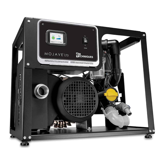
. When set to the ON (1) position, it applies input power to the internal electronics . Pump Power On/Off Switch and Circuit Breaker Touch Screen Figure 10. MOJAVE LT3 Front Panel Controls and Indicators Page 14 Air Techniques, Inc. - Page 15 OPERATING INFORMATION All MOJAVE LT3 units can be operated from either the LCD touch screen or an optional remote switch . The motor Power circuit breaker on the face of the compressor control box must be set in the ON position whether using the touch screen or the optional remote switch . The MOJAVE LT3 is designed for continuous operation .
-
Page 16: Touch Screen Controls
LCD touch screen display. See Operating Information on page 15. All MOJAVE LT3 units have a color LCD touch screen display located on the front control box panel . This display is used to start the unit and show system operating status . It also serves as an input for controlling operation and adjusting system parameters . - Page 17 Temperature ( ο F) Widget - Current ambient temperature of room with max temperature limit indicator . Temperature Digital Readout Max Temperature Voltage Indicator Range Indicator Voltage Digital Readout Note: Indicator will turn red when ο room temperature exceeds 105 Voltage Min/Max Temperature Indicator Range Indicator Air Techniques, Inc. Page 17...
- Page 18 Scroll Button 2. SETTINGS SCREEN a . INFORMATION Model - Air Techniques model number . ii. SN - Unit serial number . iii. PCB - Indicates control board serial number . iv. Firmware - Indicates latest installed firmware and revision .
- Page 19 Run-Time - Shows time that unit has been running (hours) g . ALARM HISTORY Shows the last forty (40) alarms triggered . Push any listed ALARM button to get details of alarm, such as suggested tasks and date alarm was triggered . Air Techniques, Inc. Page 19...
- Page 20 TOUCH SCREEN CONTROLS ALARMS MOJAVE LT3 checks operation via the Intelligent Monitoring System and alerts the user to problems by displaying Warnings or Errors in the upper left corner of the Home Screen . Warnings notify the user of conditions effecting operation while Errors are critical problems disabling operation . As shown below, explanation of the Warning or Error is expanded by pressing the displayed alert .
- Page 21 Separator below minimum speed. Re-enable motor? Motor VFD error detected. Contact Technician. Pressure Sensor Malfunction Pressure Sensor 3 1020011-0 Malfunction Alert Problem Fault Example Pressure Sensor Malfunction Contact Technician Hide Settings Next Home Screen Showing Error Example Error Screen Air Techniques, Inc. Page 21...
-
Page 22: Maintenance
. Using CleanStream Cleaner helps the MOJAVE LT3 system to remove any built up deposits in the piping system . Perform the initial cleaning by performing the daily maintenance procedure provided below . - Page 23 . 5 . With the vacuum pump on and handpiece valves open, aspirate the CleanStream solution from dispenser . 6 . After each cleansing procedure, disconnect the hand pieces and rinse the dispenser . Air Techniques, Inc. Page 23...
-
Page 24: Accessories/Options
ACCESSORIES/OPTIONS Accessories/Equipment Options. The following lists the ordering number and description for accessory components available to maintain the MOJAVE product family . Contact an authorized Air Techniques’ dealer for information . Description Part Number Remote Control Panels with 24V switches:... -
Page 25: Troubleshooting
Motor VFD error a. Various issues with the VFD a. Check for the VFD error code under detected. Contact can cause this problem the 'Settings -> Info' screen and Technician. contact Technical Support Air Techniques, Inc. Page 25... -
Page 26: Warranty
Any item returned under warranty, will be repaired or replaced at our option at no charge provided that our inspection shall indicate it to have been defective . Air Techniques, Inc . is not liable for indirect or consequential damages or loss of any nature in connection with this equipment . Dealer labor, shipping and handling charges are not covered by this warranty . - Page 27 NOTES Air Techniques, Inc. Page 27...
- Page 28 For over 50 years, Air Techniques has been a leading innovator and manufacturer of dental products . Our priority is ensuring complete satisfaction by manufacturing reliable products and providing excellent customer and technical support . Whether the need is digital imaging, utility room equipment or merchandise, Air Techniques can provide the solution via our network of authorized professional dealers .
Need help?
Do you have a question about the MOJAVE LT3 and is the answer not in the manual?
Questions and answers