Air Techniques ProVecta 3D Prime Installation Instructions Manual
Hide thumbs
Also See for ProVecta 3D Prime:
- Installation instructions manual (44 pages) ,
- Operating instructions manual (160 pages) ,
- Installation instructions manual (52 pages)

Related Manuals for Air Techniques ProVecta 3D Prime


Summary of Contents for Air Techniques ProVecta 3D Prime
- Page 1 ProVecta 3D Prime and ProVecta 3D Prime Ceph Installation instructions 0297 2210201032L41 *2210201032L41*...
-
Page 3: Table Of Contents
Overview ......ProVecta 3D Prime ... ProVecta 3D Prime Ceph .. -
Page 4: Important Information
These installation and operating instructions are an integral part of the unit. Part number Air Techniques shall not be held liable and offers no guarantees of the safe and Serial number smooth operation of this unit if you fail to... -
Page 5: Copyright Information
Printing or copying these Installation and Operat- ing Instructions, including excerpts thereof, may Recycling only be carried out with the written approval of Air Techniques. Keep dry This way up / store and transport in an upright position Keep away from sunlight during storage Refer to Operating Instructions. -
Page 6: Safety
ProVecta 3D Prime Ceph licensed medical practitioner. ProVecta 3D Prime Ceph is a computed tomog- Caution: By virtue of Federal Law, the raphy x-ray unit intended to generate 3D, panor- software may only be sold to dentists or amic and cephalometric X-ray images in dental bought on behalf of a dentist. -
Page 7: Specialist Personnel
All installation, resetting, alteration, expansion, ❯ reduced electromagnetic immunity, and repair work must be carried out either by leading to an erroneous operation Air Techniques personnel or by a suitably quali- mode. fied person approved by Air Techniques. Protection from electric NOTICE... -
Page 8: Essential Performance Charac
Only use accessories and optional items speci- ❯ The unit is to be connected to a computer that fied or approved by Air Techniques. can be connected to the Internet. Therefore, the Only use original working parts and spare ❯... -
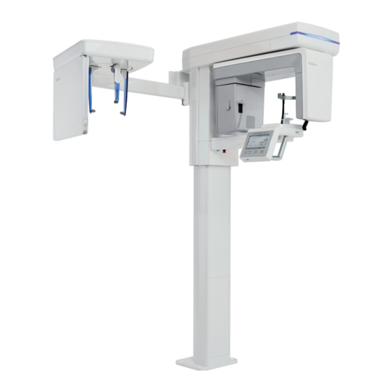
Page 9: Product Description
Product description Product description Overview ProVecta 3D Prime 15 14 3D and panoramic X-ray unit Hygienic protective covers for bite block Wall bracket Bite block Frame grabber card Holder for bite block USB dongle Chin holder for maxillary joint image... -
Page 10: Provecta 3D Prime Ceph
Product description ProVecta 3D Prime Ceph 15 14 3D, Ceph and panoramic X-ray unit Bite block Wall bracket Holder for bite block Frame grabber card Chin holder for maxillary joint image USB dongle Chin support for edentulous jaws USB stick containing device-specific cali-... -
Page 11: Scope Of Delivery
(possible variations due to country-spe- cific requirements and/or import regulations): ProVecta 3D Prime ....A7750 – Fiber optic cable 10 m / 33 ft –... -
Page 12: Optional Items
Bottom wall bracket set, 16 inch, short (wall/wall installation) ....A7754 ProVecta 3D Prime Ceph only Set of silicone pads Ear rods and nose support . -
Page 13: Technical Data
Maximum power Fuses* (2 pcs.) T 10.0 AH / 250 V~ (IEC 60127-2, Sheet * The fuses may only be replaced by Air Techniques or by a body authorized by Air Techniques. Classification Medical Device Class (MDR) FDA classification (CFR Title 21) -
Page 14: X-Ray Tube Performance Data
Product description X-ray emitter Nominal voltage, high-voltage generator 60 - 99 (±10 %) Nominal current, high voltage generator 4 - 16 (± 10%, max. 75 kV 16 mA, max. 99 kV 10 mA) Cooling, high-voltage generator Automatic monitoring Shut-off at ≥ 60°C Additional filtration 1.5 + 3.0 (added automatically for CBCT) mm Al... - Page 15 Product description Maximum Rating Charts DC (Center Grounded) Constant potential high-voltage generator Nominal Focus Spot Value: 0.5 70kV 80kV 60kV 90kV 50kV 100kV EXPOSURE TIME [s] Emission and Filament Characteristics Constant potential high-voltage generator Nominal Focus Spot Value: 0.5 80kV 100kV 50kV FILAMENT CURRENT [A]...
- Page 16 Product description Anode Thermal Characteristics 175 W COOLING HEATING TIME (min) Detector Pano/CBCT Cephalometric projec- tions Brand Xmaru1404CF Xmaru 2602CF Type CMOS photodiode array Pixel size μm 49.5 99 (2x2 binning) 200 (2x2 binning) 198 (4x4 binning) Sensor size 230 x 160 x 26 279 x 110 x 20 9.06 x 6.30 x 1.02 10.98 x 4.33 x 0.79...
- Page 17 Product description Electromagnetic compatibility (EMC) Interference emission measurements High-frequency emissions in accordance with CISPR 11 Group 1 Interference voltage at the power supply connection Class A CISPR 11:2009+A1:2010 Electromagnetic interference radiation Class A CISPR 11:2009+A1:2010 Emission of harmonics Class A IEC 61000-3-2:2005+A1:2008+A2:2009 Voltage changes, voltage fluctuations and flicker emis- sions...
- Page 18 Product description Immunity to interference levels by near fields of wireless HF communication devices Radio service Frequency band Test level GSM 1800 CDMA 1900 GSM 1900 1700 - 1990 DECT LTE bands 1, 3, 4, 25 UMTS Bluetooth WLAN 802.11 b/g/n 2400 - 2570 RFID 2450 LTE band 7...
-
Page 19: Dimensions
Product description Dimensions ProVecta 3D Prime 573 mm 22,56 in 1212 mm 47,72 in 2210201032L41 2108V005... - Page 20 Product description ProVecta 3D Prime Ceph 573 mm 22,56 in 1212 mm 47,71 in 1941 mm 76,42 in 2210201032L41 2108V005...
-
Page 21: Model Identification Plate
Product description Model identification plate Type plate of the unit Type plate of the X-ray tube Conformity assessment This device has been subjected to conformity acceptance testing in accordance with the cur- rent relevant guidelines of the European Union. This equipment conforms to all relevant require- ments. -
Page 22: Function
Product description Function Cephalometric X-ray unit 3D and panoramic X-ray unit Sensor (Ceph) Ear rods with holder Nose support On/off switch Emergency stop switch Recording digital cephalometric radiographs, the Status LED patient’s head is scanned line by line with a fan- Rotating unit shaped, flat X-ray beam. -
Page 23: Positioning Aids
Product description Positioning aids Panoramic Bite block and adapter bite block Chin holder for edentulous jaws Chin holder for maxillary joint image Lever for positioning the Frankfurt plane positioning beam Frankfurt plane of the X-ray positioning beam Head supports with cushion Chin holder for sinus image Positioning aid, e. -
Page 24: Exposure Button
Product description Sensor (Ceph) Ear rods with holder Nose support Cephalometric pro- jections Ear rods with holder Nose support Indicator lamp (LED) Exposure button Memory card slot Carpus plate The applied parts in accordance with IEC 60601-1 for the cephalometric unit are: –... - Page 25 Product description Panoramic X-ray device Active sensor surface Geometric mid-point of the active sensor surface Cephalometric X-ray unit Line sensor housing Active sensor surface 2210201032L41 2108V005...
-
Page 26: Requirements
Only qualified specialists or persons Children and pregnant women must consult a ❯ trained by Air Techniques may install, doctor before recording an X-ray image. connect, and commission the unit. No person other than the patient is permitted ❯... -
Page 27: System Requirements For The Reconstruction Computer
PC and the unit. The processor and graphics board must meet the specifications and system requirements to ensure a faultless reconstruction. Should these requirements not be met, Air Techniques does not provide any guarantee for faultless reconstruction. -
Page 28: Installation
Installation Check to see if the Tiltwatch display has been ❯ Installation activated. NOTICE Danger to components due to electro- static discharge (ESD) Establish equipotential bonding Tiltwatch ❯ between the person carrying out the work and the surroundings, e.g. via a wrist strap that is connected to the basic unit. - Page 29 Installation Take out the accessories carton, the Ceph part Fold the outer carton away to the outside. ❯ ❯ and the carton with cross-member and rotating unit and place them to one side. Take out the column with column slide and ❯...
-
Page 30: Setting Up The Unit
Installation Setting up the unit Installation variants for ProVecta 3D Prime Standard Standard Standard Walls not with addi- Without With under- able to take tional wall underfloor floor heating the load bracket at heating the bottom Weight in kg (with foot) - Page 31 Installation Installation variants for ProVecta 3D Prime Ceph Standard Standard Standard Walls not with addi- Without With under- able to take tional wall underfloor floor heating the load bracket at heating the bottom Weight in kg (with foot) Top wall bracket...
- Page 32 Installation Attach the upper wall mounting bracket (refer ❯ Requirements to the accessories carton) to the column. – Easily accessible electrical connections – The electrical connections comply with the requirements (see "4 Technical data") Tools required: – Hexagon key SW13 –...
- Page 33 Installation Secure the wall mounting bracket to the retain- Roughly align the column. ❯ ❯ ing plate. Here, the wall mounting bracket can be attached in several different mounting posi- tions. Mark the anchor holes centrally on the wall ❯ mounting bracket(s).
- Page 34 Installation Roughly align the column again. Attach the column with four screws and wash- ❯ ❯ ers to the stand. Roughly align the device via the floor stand. ❯ Drill the anchor holes for the floor plate. ❯ It is possible to drill through the holes in the floor plate (max.
- Page 35 Installation Remove the carton. Check to make sure that the mounting faces ❯ ❯ Remove enough of the foam parts such that on the cross-member and on the column slide the cross-member with rotating unit can be are clean and free of damage. taken out.
- Page 36 Installation One person secures the cross-member with ❯ During the following steps, maintain the rotating unit, while a second person attaches correct sequence when tightening the the cross-member with the two bushings and screws. screws to the column slide. Use the transport grips to lift the cross-mem- ❯...
- Page 37 Installation Position the assembly aid for the locating Tighten the locating screw by hand. To do this, ❯ ❯ screw and carefully tap in the locating screw it may be necessary to exert some pressure on with a hammer until it reaches the stop. the screw.
- Page 38 Installation Check the alignment of the cross-member with Mount the lever for positioning of the Frankfurt ❯ ❯ a spirit level. plane beam localizer (in the accessories) to the Correct its position with the adjustable feet on rotating unit. the floor plate. To do this, it may be necessary to loosen the screws on the floor plate and on the wall mounting brackets.
- Page 39 Installation Connecting the cross-member Secure the clamp with a screw. ❯ Route the cables from the column slide ❯ through the cable attachments. A01-CN1706 A01-CN1702 Guide the cables A01-CN1702 and A01- ❯ CN1706 through the clamps. 2210201032L41 2108V005...
- Page 40 Installation Connect the wiring connections from the col- Attach the ferrite core of cable A01-CN1706 ❯ ❯ umn slide to the cables and sockets on the close to PCBA01. cross-member. Using cable ties, tie together all cables that ❯ have been routed from the cross-member to the column slide and secure them.
- Page 41 Installation Remove the screw and threaded pin from the Loosen the four screws of the mounted covers, ❯ ❯ cross-member securing the rotating unit. but do not remove them completely. Remove the red adhesive tape. ❯ Place the screws for the transport protection in ❯...
- Page 42 Installation Secure the cover with a screw and washer. Attach the sensor cover and retightened the ❯ ❯ loosened screws. In the process, make sure that the four mount- ings on the sensor cover are plugged in between the cast bracket and cover. 2210201032L41 2108V005...
- Page 43 Installation Mount the lower covers on the left and right of Check to make sure that the covers are seated ❯ ❯ the cross-member. correctly. The Y-cover (white plastic panel) must lie between the housing and the cast part of the cross-member.
- Page 44 Installation Tighten the lower covers on the left and right. Mount the lower cover to the front of the cross- ❯ ❯ member. Left-hand cover: three screws with wash- ers screwed in from above Left-hand cover: one screw with washer screwed in from below Right-hand cover: three screws with washers screwed in from above...
- Page 45 Installation Mount the upper cover of the cross-member. Mount the upper column cover. ❯ ❯ For the installation use screws with washers. For the installation use screws with washers. 2210201032L41 2108V005...
- Page 46 Installation Mount the lower column cover. Installing the Ceph head ❯ For the installation use screws with washers. Install the Ceph head. ❯ Thread the cable from the Ceph head through the Ceph arm. Then connect this to the cable from the column slide.
- Page 47 Installation Use four screws, four washers and four protec- Installing the ear rod holder ❯ tive caps to attach the covers to the Ceph The ear rod holder on the left includes a head. metal pin. Use two screws to attach the left and right ear ❯...
-
Page 48: Preparation Of The Reconstruction Computer
The unit supports the following imaging pro- Follow the further instructions given by the ❯ grams: installation wizard. – VisionX from Version 2.4 from Air Techniques can be downloaded from www.airtechni- Installing the frame grabber card and USB ques.com dongle The enclosed frame grabber card is installed in ❯... - Page 49 Installation 250 VAC max. ProVecta 3D Prime Ceph A01 (internal) Reconstruction computer with frame grab- GND (internal) ber card Exposure switch / door switch / man- Exposure switch ual switch for height adjustment Door contact Mains AC power connection Exposure switch / door switch / man-...
- Page 50 Installation Installing the exposure switch Route the cable of the exposure switch though ❯ the cable bushing to the front into the column. Connect the cable to the PCB A07. ❯ Slot X4 Removing the housing cover In order to be able to connect the unit, the front cover on the column needs to be removed.
- Page 51 Installation Remove the cable bridge from slot X8. safety requirements in accordance with ❯ EN60601-1. Connect the equipotential bonding cable (not ❯ included in the scope of delivery) to the con- nection on the unit. The connection complies with DIN 42801. The connection for the equipotential bonding is marked with the symbol Connecting the device to a computer...
- Page 52 Installation Remove the protective cap from the connector Electrical safety when making connections ❯ of the fiber optic cable and from the plug Make sure that none of the electrical cables ❯ socket on the PCB and plug the fiber optic leading to the unit are under any mechanical cable into the PCB.
-
Page 53: Commissioning And First Start-Up
Installation Commissioning and first Layout as 2/PE AC 200–240 V (US) Connect the wires of the mains connection ❯ start-up cable to the mains. NOTICE Short circuit due to the build-up of condensation Do not switch on the unit until it has ❯... -
Page 54: Electrical Safety Checks
Installation Use the main power switch to switch the unit Move the unit to the minimum height level of ❯ ❯ the unit. Are there any suspicious noises? Is there a sufficient distance between the top cover of the housing and the ceiling? Electrical safety checks Carry out the electrical safety check according ❯... -
Page 55: Checking The Installation
Installation Checking the installation Check for correct alignment when fasten- ing the adjustment cam. The beveled side The settings are described using the must face downwards. example of the VisionX imaging software. Remove the adjustment cam and screw it back ❯... -
Page 56: Carrying Out A Functional Test
Installation Start the service tool on the reconstruction Insert the pano test phantom in the holder. ❯ ❯ computer. Taking the X-ray image To do this, run the file ServiceTool initial instal- Take a test image. ❯ lation under C:\ProgramData\AIR TECHNI- Parameters: Pano Standard, HD, patient shape QUES\VisionX\WorkstationService\VistaVox- "Normal", jaw arch "Normal", 60 kV, 4 mA... - Page 57 Installation Taking the X-ray image Take a test image. ❯ Parameters: CBCT, image volume "Normal", HD, patient shape "Normal", 94 kV, 8 mA Evaluate the test image. ❯ The image must be uniform and free of arti- facts. The visible object must be square on the inside and outside.
-
Page 58: Troubleshooting
Troubleshooting Troubleshooting CAUTION Any oil leaking from the X-ray tube in the event of a fault is harmful. Wipe up any oil immediately. ❯ Do not swallow the oil. ❯ Stop using the unit and inform a service technician. ❯ Tips for operators and service technicians Any repairs above and beyond routine maintenance may only be done by suitably qualified per- sonnel or by one of our service technicians. - Page 59 Troubleshooting Error Possible cause Remedy Error messages during start of Energy-saving options incor- Deactivate the energy-saving ❯ the acquisition of an X-ray rectly configured options in Windows and the image or during shut down of BIOS completely. the PC Supply voltage for graphic card Check the plug connections.
- Page 64 Hersteller / Manufacturer: DÜRR DENTAL SE Höpfigheimer Str. 17 74321 Bietigheim-Bissingen Germany www.duerrdental.com Manufactured for / Distributed by: Air Techniques, Inc. 1295 Walt Whitman Road Melville, New York 11747-3062, USA Phone: 800-247-8324 Fax: 888-247-8481 www.airtechniques.com...
Need help?
Do you have a question about the ProVecta 3D Prime and is the answer not in the manual?
Questions and answers