Table of Contents
Advertisement
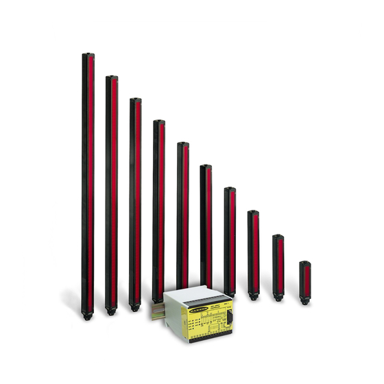
Measuring Light Screen System (MAC Series Controllers)
Controller Models MAC-1, MACN-1, MACP-1,
MACV-1, MACI-1, MAC16N-1, MAC16P-1
(See Section 1.1 for additional, model-specific features)
• Measuring Light Screen system for inspection and profiling
applications.
• Modular system with compact controller and a variety of BMEL/
BMRL series MINI-ARRAY emitters and receivers.
• Sensors available with either 9.5 mm (3/8") or 19.1 mm (3/4")
beam spacing and with array lengths from 6" to 4'
(in 6" increments), plus 5' and 6' models.
• Controller is programmable for any one or two of ten
measurement modes (depending on model) and any one of four
scanning modes, using a computer running Windows
Vista, or 7 and the Banner-supplied
• Software is also supplied for display of error analysis (via
controller self-diagnostics) and for sensor alignment.
• System status, including alignment, is displayed via LED
indicators on the controller and on the receivers.
• Controller may be programmed for blanking to ignore activity in
one or two fields along the length of the array.
• Programmable hysteresis at the high and/or low limit of each
measurement area provides smoothing of output response;
also programmable for number of consecutive scans before an
output update.
• Separate gate input (e.g., from a presence sensor) allows control
of scan initiation.
•
Supports serial communication with a computer or PLC via RS-
232C interface; enables a computer or PLC to process scan data
and/or initiate scans; serial data may be either ASCII or binary.
WARNING . . .
!
Never use these products as sensing devices for personnel protection. Doing so could lead to serious injury or death.
These sensors do NOT include the self-checking redundant circuitry necessary to allow their use in personnel safety applications. A
sensor failure or malfunction can cause either an energized or de-energized sensor output condition. Consult your current Banner
Safety Products which meet OSHA, ANSI and IEC standards for personnel protection.
Printed in USA
A-GAGE
®
Instruction Manual
Features
software
Not To Be Used for Personnel Protection
MINI-ARRAY
.XP,
®
04/12
®
P/N 43298 rev. F
Advertisement
Table of Contents

Related Manuals for Banner A-GAGE MINI-ARRAY MAC Series


Summary of Contents for Banner A-GAGE MINI-ARRAY MAC Series
- Page 1 These sensors do NOT include the self-checking redundant circuitry necessary to allow their use in personnel safety applications. A sensor failure or malfunction can cause either an energized or de-energized sensor output condition. Consult your current Banner Safety Products which meet OSHA, ANSI and IEC standards for personnel protection.
-
Page 2: Table Of Contents
Serial Data Format ............39 Banner Engineering Corp. -
Page 3: System Overview
System Overview Instruction Manual 1. System Overview ® The Banner A-GAGE MINI-ARRAY measuring light screen is ideal for applications such as on-the-fly product sizing and profiling, edge-guiding and center-guiding, loop tensioning control, hole detection, parts counting, die ejection verification, and similar uses. -
Page 4: System Features
Red Blocked LED EMTR RCVR POWER 15 14 13 12 11 10 Green Align LED Yellow Marginal Alignment LED RS-232 Port Figure 1-2. A-GAGE MINI-ARRAY System features Banner Engineering Corp. Minneapolis, MN U.S.A. • www.bannerengineering.com • Tel: 763.544.3164 P/N 43298 rev. E... - Page 5 Blanking may be set automatically (Auto Blanking) or specified using the supplied PC software. • MAC16N-1: 16 discrete open-collector NPN (current sinking) transistor outputs. • MAC16P-1: 16 discrete open-collector PNP (current sourcing) transistor outputs. Banner Engineering Corp. Minneapolis, MN U.S.A. • www.bannerengineering.com • Tel: 763.544.3164...
- Page 6 System, and totals of beams blocked, made, and blanked. Built-in system diagnostics can be used to assess emitter and receiver hardware errors. Banner Engineering Corp. Minneapolis, MN U.S.A. • www.bannerengineering.com • Tel: 763.544.3164...
-
Page 7: System Components
1514 mm (59.62") MAQDC-575C 22.7 m (75') straight MAQDC-5100C 30.3 m (100') BMEL7232A / BMRL7232A 1819 mm (71.62") MAQDC-5125C 37.9 m (125') MAQDC-5150C 45.5 m (150') Banner Engineering Corp. Minneapolis, MN U.S.A. • www.bannerengineering.com • Tel: 763.544.3164 P/N 43298 rev. E... - Page 8 Dimensions for all MAC Series Controllers listed above are: 110 x 100 x 75 mm (4.3" x 3.9" x 3.0"); see Figure 2-2. * See Section 5.5.3 for a detailed description of available scan analysis modes. Banner Engineering Corp. Minneapolis, MN U.S.A.
-
Page 9: Specifications
Cables measure 8.1 mm (0.32" ) dia., and are shielded and PVC-jacketed; conductors are 20-gauge. Connections • Use only Banner cables, which incorporate a "“twisted pair” for noise immunity on RS-485 data communication lines. • Emitter and receiver cables may not exceed 250' each. -
Page 10: Emitter And Receiver Dimensions
BMEL60..A / BMRL60..A 1877.0 mm (73.9") 1910.0 mm (75.2") 1853.0 mm (73.0") BMEL72..A / BMRL72..A Figure 2-1. Emitter and receiver mounting dimensions and defined area location Banner Engineering Corp. Minneapolis, MN U.S.A. • www.bannerengineering.com • Tel: 763.544.3164 P/N 43298 rev. E... -
Page 11: Controller Specifications
MACP-1: Up to 15 Controllers may be given unique address for RS-485 party line. .XP, Vista, or 7 Controller Programming Via RS-232 to PC-compatible computer running Windows ® operating system and using Banner-supplied software (see user manual). Banner Engineering Corp. Minneapolis, MN U.S.A. • www.bannerengineering.com • Tel: 763.544.3164... -
Page 12: Controller Dimensions
Slot for screws (2) M3.5 x 0.6 mm (2) 7.1 mm Din mounting tab (0.28") (supplied) Figure 2-2. Control module dimensions and mounting hole locations Banner Engineering Corp. Minneapolis, MN U.S.A. • www.bannerengineering.com • Tel: 763.544.3164 P/N 43298 rev. E... -
Page 13: Installation And Mechanical Alignment
3. Installation and Mechanical Alignment 3.1 Emitter and Receiver Mounting Banner MINI-ARRAY emitters and receivers are small, lightweight, and easy to mount; the mounting brackets (supplied) allow ±30 degrees rotation. From a common point of reference, make measurements to position the emitter and receiver in the same plane with their midpoints directly opposite each other. -
Page 14: Controller Mounting
Black Terminal 8 White Trim off the foil shield and the braided shield at the point where the wires exit the cable (see Figure 3-4). Banner Engineering Corp. Minneapolis, MN U.S.A. • www.bannerengineering.com • Tel: 763.544.3164 P/N 43298 rev. E... -
Page 15: Controller Wiring And Output Hookups
RS485 10-30V dc 16-30V dc Gate 1.2 A Max. 150 mA 150 mA EMITTER and Max. Max. RECEIVER CABLES ALARM Figure 3-6. Model MACP-1 hookup Banner Engineering Corp. Minneapolis, MN U.S.A. • www.bannerengineering.com • Tel: 763.544.3164 P/N 43298 rev. E... - Page 16 1.2 A Max. 150 mA 10 mA 10 mA EMITTER and Max. V out 2 Max. RECEIVER CABLES ALARM V out 1 Figure 3-8. Model MACV-1 hookup Banner Engineering Corp. Minneapolis, MN U.S.A. • www.bannerengineering.com • Tel: 763.544.3164 P/N 43298 rev. E...
- Page 17 16-30V dc 10-30V dc 1.2 A Max. EMITTER and Gate RECEIVER CABLES 16 Solid-state Ouputs through 150 mA Max each Figure 3-10. Model MAC16P-1 hookup Banner Engineering Corp. Minneapolis, MN U.S.A. • www.bannerengineering.com • Tel: 763.544.3164 P/N 43298 rev. E...
-
Page 18: System Power
Prepare an RS-232 cable using a DB-9 male connector with the connections shown in Figure 3-12. NOTE: DO NOT use a “null modem” RS-232 cable. Banner Engineering Corp. Minneapolis, MN U.S.A. • www.bannerengineering.com • Tel: 763.544.3164 P/N 43298 rev. E... -
Page 19: Software Installation
After the software is installed, a MINI-ARRAY shortcut icon is placed on your desktop. Double-click on the MINI-ARRAY icon to launch the program, then follow the configuration and setup procedures described in Section 5 of the primary manual. Figure 4-1. MINI-ARRAY software installation: dialog boxes Banner Engineering Corp. Minneapolis, MN U.S.A. •... -
Page 20: Controller Configuration
Parameter Setup Files (PSF) are programmed configurations that can be stored in the control module’s non-volatile memory. The Banner software can store various PSFs in computer files for instant call-up of a particular configuration. The Banner software also provides two additional features: An Alignment screen and a Diagnostics screen 5.1 Communications Setup The MINI-ARRAY software permits serial communication via RS-232 between the MAC controller and the PC. -
Page 21: Alignment
See Section 5.5.4 for more information about blanking. Figure 5-3. MINI-ARRAY software Alignment screen (models Figure 5-4. Alignment screen (models MAC16P-1 and MAC-1, MACP-1, MACN-1, MACV-1, and MACI-1) MAC16N-1) Banner Engineering Corp. Minneapolis, MN U.S.A. • www.bannerengineering.com • Tel: 763.544.3164 P/N 43298 rev. E... -
Page 22: Parameter Setup Files (Psfs)
Section 5.5 describes them in detail. Figure 5-5. MINI-ARRAY software PSF Configuration (models MAC-1, MACP-1, MACN-1, MACV-1, and MACI-1) Figure 5-6. MINI-ARRAY software PSF Configuration (models MAC16N-1 and MAC16P-1) Banner Engineering Corp. Minneapolis, MN U.S.A. • www.bannerengineering.com • Tel: 763.544.3164... - Page 23 MINI-ARRAY Controller Configuration Instruction Manual 43989 Figure 5-7. Use the PSF Configuration screen to program each control module individually (see Figure 5-10 for 16-output models) Banner Engineering Corp. Minneapolis, MN U.S.A. • www.bannerengineering.com • Tel: 763.544.3164 P/N 43298 rev. E...
- Page 24 After a PSF is configured, it may be sent to the controller. The PSF may also be saved for call-up at a later time. Many PSFs may be saved within PC files for quick controller configuration whenever a setup change is required. Banner Engineering Corp. Minneapolis, MN U.S.A. •...
-
Page 25: Creating New Parameter Setup Files (Psfs)
In the case of total or contiguous beams made or broken, these settings determine the minimum and maximum number of beams required for an output. Figure 5-9. Output assignments portion of PSF Configuration screen Banner Engineering Corp. Minneapolis, MN U.S.A. •... - Page 26 If the Scan Number is set to five, the outputs will not change unless the condition is true for five consecutive scans. Figure 5-10. PSF Configuration screen (models MAC16P-1 and Figure 5-11. Edit Discrete Outputs screen MAC16N-1) Banner Engineering Corp. Minneapolis, MN U.S.A. • www.bannerengineering.com • Tel: 763.544.3164 P/N 43298 rev. E...
- Page 27 Null/Span adjustment procedure when neither the Null Update nor the Span Update functions are accessed. When this time-out condition occurs, the MAC controller automatically cancels the Null/Span adjustment procedure and returns to the previously saved settings. Banner Engineering Corp. Minneapolis, MN U.S.A. • www.bannerengineering.com • Tel: 763.544.3164...
-
Page 28: Analysis Mode Selection
BMEL 3616A and the Banner-supplied software via the built-in RS-232 or RS-485 interface. The Emitter Banner MINI-ARRAY System can be programmed for any one or two of the following 48 – Scan Analysis Modes (see Figure 5-13 for examples): In Last Beam Made Mode, 40 –... -
Page 29: Blanking Specifications
Blanking, Abort Auto Blanking, Save to File, Read From File, Cancel, OK, and Edit. Clear Blanking Fields removes all blanking specifications. Restore Controller Settings reads the previously saved blanking specifications from the MINI-ARRAY controller. Banner Engineering Corp. Minneapolis, MN U.S.A. • www.bannerengineering.com • Tel: 763.544.3164... - Page 30 Blank Selected/Clear Selected feature allows the user to select/clear rows of channels. OK button adds the new blanking additions to the Alignment screen. Cancel button voids the Edit changes. Banner Engineering Corp. Minneapolis, MN U.S.A. • www.bannerengineering.com • Tel: 763.544.3164...
-
Page 31: Scanning Methods
With two beams skipped, only #1, 4, 7, 10, etc. will be interrogated, and so on. Emitter Receiver Interlaced Scan improves optical resolution in the middle one-third of the scanning range. Figure 5-17. Interlaced Scan Banner Engineering Corp. Minneapolis, MN U.S.A. • www.bannerengineering.com • Tel: 763.544.3164 P/N 43298 rev. E... -
Page 32: Control Mode Selection
Compress Data option, in many cases, reduces the number of data bytes sent for each analysis mode from two to one byte. See the Appendix for additional information. Banner Engineering Corp. Minneapolis, MN U.S.A. • www.bannerengineering.com • Tel: 763.544.3164... -
Page 33: Psf Assignment And Storage
For example, type the name Inspect1.psf, and select selected drive (default is C:), and the program automatically returns to the PSF Configuration screen. Figure 5-21. MINI-ARRAY software: Save PSF screen Banner Engineering Corp. Minneapolis, MN U.S.A. • www.bannerengineering.com • Tel: 763.544.3164... - Page 34 Step simulates a gate input command. To close the PSF Configuration screen, select either Quit or Exit. Figure 5-23. MINI-ARRAY software: PSF Output Analysis Banner Engineering Corp. Minneapolis, MN U.S.A. • www.bannerengineering.com • Tel: 763.544.3164 P/N 43298 rev. E...
-
Page 35: System Operation
All three LEDs (yellow, red and green) ON at the same time indicates a receiver failure. Run the Diagnostics software (see Section 6.3) to determine the cause of the receiver failure. Banner Engineering Corp. Minneapolis, MN U.S.A. • www.bannerengineering.com • Tel: 763.544.3164... -
Page 36: Controller Operating Status Indicators
ALARM RS-232 2 - TX 3 - RX 5 - COM EMTR RCVR POWER 15 14 13 12 11 10 Figure 6-2. Controller front panel Banner Engineering Corp. Minneapolis, MN U.S.A. • www.bannerengineering.com • Tel: 763.544.3164 P/N 43298 rev. E... -
Page 37: Diagnostics Program
The Diagnostics routine also displays the part number and date code of the controller, which may be useful information if factory-assisted troubleshooting by telephone is required. Figure 6-3. MINI-ARRAY software: Main Menu Figure 6-4. MINI-ARRAY software: Diagnostics screen Banner Engineering Corp. Minneapolis, MN U.S.A. • www.bannerengineering.com • Tel: 763.544.3164 P/N 43298 rev. E... - Page 38 ® MINI-ARRAY System Operation Instruction Manual Banner Engineering Corp. Minneapolis, MN U.S.A. • www.bannerengineering.com • Tel: 763.544.3164 P/N 43298 rev. E...
-
Page 39: Appendix
Hex value 1C The controller ID value The termination byte is the ASCII character for a linefeed (hex value 0A). These three bytes are collectively called the Header. Banner Engineering Corp. Minneapolis, MN U.S.A. • www.bannerengineering.com • Tel: 763.544.3164 P/N 43298 rev. E... - Page 40 The first of the two bytes is the most significant. As an example, the FBB measurement mode is coded by the two-byte number: value of 262 for the Figure A-1. ASCII Data Values 0x01 0x06. Banner Engineering Corp. Minneapolis, MN U.S.A. • www.bannerengineering.com • Tel: 763.544.3164 P/N 43298 rev. E...
- Page 41 0x1c B 0x00 0x23 0x0a (a total of 5 bytes per scan) Binary Transmission, Suppress Header, Compress Data Option 2: 0x23 (1 byte per scan) Banner Engineering Corp. Minneapolis, MN U.S.A. • www.bannerengineering.com • Tel: 763.544.3164 P/N 43298 rev. E...
- Page 42 ® MINI-ARRAY Notes Instruction Manual Banner Engineering Corp. Minneapolis, MN U.S.A. • www.bannerengineering.com • Tel: 763.544.3164 P/N 43298 rev. E...
- Page 44 Banner Engineering Corp Limited Warranty Banner Engineering Corp. warrants its products to be free from defects in material and workmanship for one year following the date of shipment. Banner Engineering Corp. will repair or replace, free of charge, any product of its manufacture which, at the time it is returned to the factory, is found to have been defective during the warranty period.
Need help?
Do you have a question about the A-GAGE MINI-ARRAY MAC Series and is the answer not in the manual?
Questions and answers