Table of Contents
Advertisement
Quick Links
Advertisement
Chapters
Table of Contents

Subscribe to Our Youtube Channel
Related Manuals for Anderson TSR-3450


Summary of Contents for Anderson TSR-3450
- Page 1 404641-1 Large square bale carrier TSR-3450 Operator’s Manual 2012...
-
Page 3: Table Of Contents
Table of Contents How to Reach Us Before You Start Group Anderson Limited Warranty About this Manual Introduction General presentation of the self-loading trailer Techincal Specifications Security Coupling to the tractor Ajustements Pusher stopper Guides balle Width of the grabber... - Page 4 Self loading trailer TSR-3450 Anderson Group Operator’s Manual –...
-
Page 5: How To Reach Us
How to Reach Us When contacting Anderson, please always provide us with the following information: The product model and serial number; • Your name, address, and telephone number; • The purchase date and the invoice number; • The dealer name, address, telephone number and salesperson’s name;... -
Page 6: Group Anderson Limited Warranty
The selling dealer has no authority to make any representation or promise on behalf of Anderson or to modify the terms or limitations of this warranty in any way. - Page 7 Group Anderson Inc. (hereafter called ‘’Anderson’’). This outline is intended to assist you in awareness of Anderson’s Warranty Policies and to assure that you obtain the best service possible for your Anderson machine. Warranty is limited to 1-year (12months). This specified period begins on the date •...
- Page 8 Parts will be credited at the Dealer’s net cost. No warranty will be allowed on parts that are past due. In the event that parts must be shipped from Anderson, freight will be paid by the • Dealer and will be shipped by the most economical means to arrive in the shortest possible time.
-
Page 9: About This Manual
Discharge Illustrations The illustrations of this manual are presented as references according to the available information during the printing of this manual. Group Anderson reserves the rights to modify its machines without advance notice. Advisory Notices Warning messages! Provide information which must be read to avoid damaging the self-loading trailer. - Page 10 Self loading trailer TSR-3450 Anderson Group Operator’s Manual –...
-
Page 11: Introduction
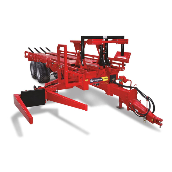
Congratulations! You have just purchased yourself an Anderson self-loading trailer. A quality piece of machinery built essentially for moving large square bales. General presentation of the self-loading trailer The following illustration shows the main components of the self-loading trailer TSR-3450 Figure 1.1 – Main components of self loading trailer Anderson Group Self loading trailer TSR-3450 –... -
Page 12: Techincal Specifications
11,37 m (447,5 po) Distance from the grabber to the 1,84 m (72.5 po) center of the table (H) Dumping angle 35˚ Total Weight 4656 kg (10265 lbs) Table 1 – Weight and dimensions Self loading trailer TSR-3450 Anderson Group Operator’s Manual –... - Page 13 - 2 hydraulic outlets Table 2 – General specifications * If loaded of 19 bales, the bales must have a maximum weight of 680 kg (1500 lbs). ** Dry hay bales. Anderson Group Self loading trailer TSR-3450 – Operator’s Manual...
- Page 14 Self loading trailer TSR-3450 Anderson Group Operator’s Manual –...
-
Page 15: Security
2 Security Your Anderson self-loading trailer was conceived to minimize the risks to the operator. However, you never should use the self-loading trailer for anything except the use that it was designed for. This self-loading trailer is equipped with a powerful hydraulic system and moving metal parts. - Page 16 Hydraulic fluid is a flammable substance, keep it in an approved packaging and always be careful when you fill the tank. Once you have finished filling the tank replace the cap on the Self loading trailer TSR-3450 Anderson Group Operator’s Manual –...
- Page 17 (see Figure 3.1). Place the pins in the holes. Figure 2.1 Attaching the loading arm If traveling, do not forget to raise the mechanical jack to avoid breakage. Anderson Group Self loading trailer TSR-3450 – Operator’s Manual...
- Page 18 Self loading trailer TSR-3450 Anderson Group Operator’s Manual –...
-
Page 19: Coupling To The Tractor
If needed adjust the tongue (B), by moving the bolts (C) when the platform is attached correctly the trailer should be level to the ground; Attach safety chains between the trailer and the tractor; Anderson Group Self loading trailer TSR-3450 – Operator’s Manual... - Page 20 Release the pressure of the tractor’s hydraulic system before connecting. Attention ! The recommended hydraulic flow to operate the trailer effectively is 30 to 58 l/min (8 to 15 GPM) Attention ! Self loading trailer TSR-3450 Anderson Group Operator’s Manual –...
- Page 21 (see 5.1) to see how to use the joystick to operate the functions of the self-loading trailer. 12- If necessary, adjust the hydraulic flow of your distributors. The trailer is now ready to load and transport your bales. Anderson Group Self loading trailer TSR-3450 – Operator’s Manual...
- Page 22 Self loading trailer TSR-3450 Anderson Group Operator’s Manual –...
-
Page 23: Ajustements
(See Figure 4.1 ) This backstop is not necessary to transport bales of 2.4m (8ft) . Figure 4.1 Ajusting the depth of the grabber Anderson Group Self loading trailer TSR-3450 – Operator’s Manual... -
Page 24: Guides Balle
The following illustration shows the optimal adjustment of the bale guides. Bale of 2.4 m (8 ft) Bale of 1.5 m (5 ft) Figure 4.2 Bale guide adjustment Self loading trailer TSR-3450 Anderson Group Operator’s Manual –... -
Page 25: Width Of The Grabber
Replace the two pins (A) and the backstop, Be sure that they are locked back in • place. When you adjust the width of the forks you must also adjust the cycle of the pusher. Risk of collision! Warning! Anderson Group Self loading trailer TSR-3450 – Operator’s Manual... -
Page 26: Pusher Cycle
Follow the indications on the Figure 4.4 to adjust the cycle of the pusher according to the width of the bales you are carrying. Figure 4.4 stopper at the end of the pusher cycle Self loading trailer TSR-3450 Anderson Group Operator’s Manual –... -
Page 27: Loading Arm Position
Raise the end of the pinchers to align the base of the cylinder with its pivot support. Replace the pin (B) by putting it in the upper hole of the pivot (E). Move the selection valve (D) to the appropriate hole (F). Anderson Group Self loading trailer TSR-3450 – Operator’s Manual... - Page 28 No weighing necessary 793 Kg (1750 lbs) 204 Kg (450 lbs) 907 Kg (2000 lbs) 394 Kg (869 lbs) 998 Kg (2200 lbs) 544 Kg (1200 lbs) table 3 weight necessary Self loading trailer TSR-3450 Anderson Group Operator’s Manual –...
-
Page 29: Operation
Lower the arm Pivot the grabber toward the trailer Pivot the grabber toward the ground Open the grabber Close the grabber Push the pusher forward Bring back the pusher (if needed) Anderson Group Self loading trailer TSR-3450 – Operator’s Manual... -
Page 30: Loading Bales
7- Activate the pusher: You have to hold in the button until the pusher reaches the end of its cycle. The pusher will return to the home position automatically. 8- Repeat steps 1 – 6 to complete the load. Self loading trailer TSR-3450 Anderson Group Operator’s Manual –... - Page 31 1 or 2 bales high to be loaded onto the trailer. Do not operate the pusher when the yellow indicator is not visible. Figure 5.3 shows the full load indicator. Full load Space available Figure 5.3 Indicateur de pleine charge Anderson Group Self loading trailer TSR-3450 – Operator’s Manual...
-
Page 32: Unloading The Trailer
When all the bales have been unloaded, bring the platform back to horizontal position. • The trailer is ready to load more bales in the fields. Self loading trailer TSR-3450 Anderson Group Operator’s Manual –... -
Page 33: Maintenance
It is very important to respect maintenance and adjustment schedule. Consult the section 6.2 Greasing points to know what maintenance and required adjustments and know how often you Warning! should follow these procedures. Anderson Group Self loading trailer TSR-3450 – Operator’s Manual... -
Page 34: Safety Stands
Your Self loading trailer must be lubricated with a grease gun in the places indicated by the sticker shown on the following picture Figure 6.2 – Grease points We recommend that you use synthetic grease. NOTE : Self loading trailer TSR-3450 Anderson Group Operator’s Manual –... - Page 35 Joint of the cylinder for the pivot of the loading arm (2) Joint of the pincher arm pivot. (5) Tandem axle pivots (4) Every 50 hours of Platform cylinder joints (4) Platform pivots (2) Draw bar (1) Anderson Group Self loading trailer TSR-3450 – Operator’s Manual...
- Page 36 Pusher cylinder joints (2) Loading arm joint (2) Self loading trailer TSR-3450 Anderson Group Operator’s Manual –...
- Page 37 Arm cylinder joints Anderson Group Self loading trailer TSR-3450 – Operator’s Manual...
- Page 38 Joint of the cylinder for the pivot of the loading arm (2) Self loading trailer TSR-3450 Anderson Group Operator’s Manual –...
- Page 39 Joint of the pincher arm pivot. (5) Anderson Group Self loading trailer TSR-3450 – Operator’s Manual...
- Page 40 Tandem axle pivots Platform cylinder joints (4) Platform pivots (2) Self loading trailer TSR-3450 Anderson Group Operator’s Manual –...
-
Page 41: Other Lubrication Points
Install the U-shaped retainer on the cylinder of the loading arm. Cleaning and general maintenance before a long period of NOTE : storage is strongly recommended. Anderson Group Self loading trailer TSR-3450 – Operator’s Manual... - Page 42 Self loading trailer TSR-3450 Anderson Group Operator’s Manual –...
-
Page 43: Troubleshooting
Anderson Service department (See section How to Reach Us at the beginning of the manual for our contact information). - Page 44 Warning! ANDERSON GROUPE Adress : 5125 de la Plaisance Chesterville (Québec) CANADA G0P 1J0 Email Service : service@grpanderson.com Tel : 1-819-382-2952 Fax Service : 1-819-382-2218 Website : www.grpanderson.com Self loading trailer TSR-3450 Anderson Group Operator’s Manual –...
- Page 45 Parts manual Large square bale carrier TSR-3450 ALWAYS KEEP THIS MANUAL WITH THE TRAILER...
- Page 47 10 – Pusher / Pusher cylinder P. 23 For any parts order, please use the parts manual to find the item(s) you need and contact your dealer to order it. ANDERSON GROUP 5125 Plaisance street Chesterville (Québec) CANADA G0P 1J0...
-
Page 48: Hydraulic Diagram
5355-6-8 63-16 63-01 HYDRAULIC DISTRIBUTOR 63-15 2 X 7237-12 63-16 2 X 7237-8 3169-8 2 X 5315-8-12 2 X 5315-8-8 6 X 5315-6-8 63-12 63-15 63-13 63-04 Anderson Group, 5125 de la Plaisance Chesterville (Québec) G0P 1J0 Email : service@grpanderson.com... - Page 49 63-11 234720 63-03 234728 63-12 234721 63-04 234730 63-13 234722 63-05 234731 63-14 234723 63-06 234732 63-15 234724 63-07 234733 63-16 234725 63-08 234734 63-17 234726 63-09 Anderson Group, 5125 de la Plaisance Chesterville (Québec) G0P 1J0 Email : service@grpanderson.com...
-
Page 50: Electrical Diagram
BROWN ELECTRICAL CABLE LIST REVERSER PART DESCRIPTION 315077 HANDLE 315161 SENSOR PURPLE PINK PUSHER 319801 315195 SENSOR WIRE BLUE ORANGE OPENER GREEN YELLOW SWIVEL GREY WHITE LIFTER Anderson Group, 5125 de la Plaisance Chesterville (Québec) G0P 1J0 Email : service@grpanderson.com... - Page 56 4 - FRAME / UNLOADING CYLINDER (T-63-12000 --> ) DETAIL G SCALE 1 / 10 DETAIL H SCALE 1 / 15 Anderson Group, 5125 de la Plaisance Chesterville (Québec) G0P 1J0 DETAIL J Email : service@grpanderson.com SCALE 1 / 15...
- Page 57 319801 BOITE DE COMPOSANTE ÉLECTRONIQUES 451180 ADAPTEUR HYDRAULIQUE 451337 ADAPTEUR HYDRAULIQUE 451172 ADAPTEUR HYDRAULIQUE 451178 ADAPTEUR HYDRAULIQUE 451335 ADAPTEUR HYDRAULIQUE 450064 ADAPTEUR HYDRAULIQUE 465583 ENSEMBLE HYDRAULIQUE D05 Anderson Group, 5125 de la Plaisance Chesterville (Québec) G0P 1J0 Email : service@grpanderson.com...
- Page 58 465582 BOLT KIT 466013 VALVE UNLOADING CYLINDER PARTS LIST ITEM PART DESCRIPTION 450863 HYDRAULIC FITTING 450716 HYDRAULIC FITTING 467082 HYDRAULIC CYLINDER 322294 GREASE FITTING 322295 GREASE FITTING Anderson Group, 5125 de la Plaisance Chesterville (Québec) G0P 1J0 Email : service@grpanderson.com...
- Page 59 4 - FRAME / UNLOADING CYLINDER (T-63-11000 --> T-63-12000 ) DETAIL A SCALE 1 / 20 DETAIL C SCALE 1 / 20 DETAIL B SCALE 1 / 20 Anderson Group, 5125 de la Plaisance Chesterville (Québec) G0P 1J0 Email : service@grpanderson.com...
- Page 60 BOLT 234016 TANDEM AXLE 218001 FLAT WASHER 500212 BOLT 465583 KIT D05 451337 HYDRAULIC FITTING 451172 HYDRAULIC FITTING 451178 HYDRAULIC FITTING 451335 HYDRAULIC FITTING 450064 HYDRAULIC FITTING Anderson Group, 5125 de la Plaisance Chesterville (Québec) G0P 1J0 Email : service@grpanderson.com...
- Page 61 465581 COUNTERBALANCE 465582 BOLT KIT UNLOADING CYLINDER PARTS LIST ITEM PART DESCRIPTION 450863 HYDRAULIC FITTING 450716 HYDRAULIC FITTING 467082 HYDRAULIC CYLINDER 322294 GREASE FITTING 322295 GREASE FITTING Anderson Group, 5125 de la Plaisance Chesterville (Québec) G0P 1J0 Email : service@grpanderson.com...
-
Page 62: Tandem
320002 CUTTER PIN 501902 WHEEL NUT 481404 COMPLETE HUB 303491 BEARING 303492 BEARING CUP 303490 SEAL 303494 BEARING 303493 BEARING CUP 481004 DUST CAP 501076 CASTLE NUT Anderson Group, 5125 de la Plaisance Chesterville (Québec) G0P 1J0 Email : service@grpanderson.com... -
Page 63: Tongue
322299 GREASE FITTING 234193 DRAW BAR 234194 WASHER 500324-1 BOLT 234192-1 TRAILER TONGUE CONE 234195 CONE PLATE 500177 BOLT 500213-2 BOLT 501036-1 NYLON NUT 234106 LOCK WASHER Anderson Group, 5125 de la Plaisance Chesterville (Québec) G0P 1J0 Email : service@grpanderson.com... -
Page 64: Rear Support With Full Load Indicator
500019 BOLT 501030 NYLON NUT 234739 REAR SUPPORT NWITH INDICATOR ASSEMBLY 234200 INDICATOR ROCKER 234199 LINK 500084 BOLT 234740 500086 BOLT 501032-1 NYLON NUT 234754 INNER HOUSING Anderson Group, 5125 de la Plaisance Chesterville (Québec) G0P 1J0 Email : service@grpanderson.com... - Page 65 DESCRIPTION 320091 PIN AND HITCH PIN 234743 RIGHT BALE GUIDE 234744 REAR SUPPORT 481012 PLASTIC CAP 500295-1 BOLT 501036 NYLON NUT DETAIL A SCALE 1 / 20 Anderson Group, 5125 de la Plaisance Chesterville (Québec) G0P 1J0 Email : service@grpanderson.com...
- Page 66 PART DESCRIPTION 320091 PIN AND HITCH PIN 234745 LEFT BALE GUIDE 234744 REAR SUPPORT 481012 PLASTIC CAP 501036 NYLON NUT 500295-1 BOLT DETAIL B SCALE 1 /20 Anderson Group, 5125 de la Plaisance Chesterville (Québec) G0P 1J0 Email : service@grpanderson.com...
-
Page 67: Platform / Pusher Cylinder Support
NYLON NUT 500443 CARRIAGE BOLT 315161 SENSOR 507061-1 BOLT 501051 NYLON NUT P00199 SLIDING PLATE DETAIL D SCALE 1 / 25 DETAIL E SCALE 1 / 12 Anderson Group, 5125 de la Plaisance Chesterville (Québec) G0P 1J0 Email : service@grpanderson.com... - Page 68 UPPER CYLINDER SUPPORT 234039 LOWER CYLINDER SUPPORT 234750 SENSOR SUPPORT 501032 NYLON NUT 315161 SENSOR 507061-1 BOLT 501051 NYLON NUT P00199 SLIDING PLATE 500442 CARRIAGE BOLT 507023 U-BOLT Anderson Group, 5125 de la Plaisance Chesterville (Québec) G0P 1J0 Email : service@grpanderson.com...
- Page 69 500088 BOLT P00205 BUMPER SENSOR 500044 BOLT 501031 NYLON NUT PARTS LIST ITEM PART DESCRIPTION 450717 HYDRAULIC FITTING 322299 GREASE FITTING 450716 HYDRAULIC FITTING 467314 HYDRAULIC CYLINDER Anderson Group, 5125 de la Plaisance Chesterville (Québec) G0P 1J0 Email : service@grpanderson.com...
Need help?
Do you have a question about the TSR-3450 and is the answer not in the manual?
Questions and answers