Table of Contents
Advertisement
Quick Links
Advertisement
Chapters
Table of Contents

Related Manuals for Anderson RB 680


Summary of Contents for Anderson RB 680
- Page 1 # 404612-2 Round Bale Wrapper RB 680 Operator’s Manual 2011...
- Page 3 The il lustrations in th is m anual are p resented for yo ur ref erence ac cording to the la test information ava ilable at the mo ment o f printing . ANDERSON GROUP reserve s the righ t t o...
-
Page 4: Table Of Contents
Table of Contents 1 ANDERSON Limited Warranty ................. 8 One-Year Limited Warranty ..................8 Documents ......................8 Problem Resolution ....................8 Modifications ......................8 Warranty Exemptions ................... 10 Exclusive Remedy ....................10 2 Safety ........................11 Safe Operators ..................... 11 Danger Zone...................... - Page 5 Other Lubrication Points ..................34 Cleaning and Other Maintenance ................35 Storage ....................... 35 7 Troubleshooting: Problems and Solutions ............. 36 Reset Procedure ....................38 8 Optional Equipment ....................40 Stabilizers ......................40 Modifying Gears to Reduce Stretch Ratio ............... 40 Bale Loading Arm and Film Roll Support ..............
- Page 6 - Product model and serial number; - Purchase date and invoice number; - Dealer name, address, and telephone number and salesperson name; - Precise and detailed description of your problem. ANDERSON GROUP Address: 5125 de la Plaisance Chesterville (Québec) CANADA G0P 1J0 Email Service: service@grpanderson.com...
- Page 7 ANDERSON LIMITED WARRANTY FORM Warranty form must be completed and returned. Please fill in this form with information about your new machine. Please return this form to us in the 15 da ys following the date of de livery to val idate your warranty. Details of the warranty provided can be found in the operator’s manual.
- Page 9 For your personal records, we recommend tha t you fill in this form with information about your machine. Type of Machine: Model: Options: Serial Number: Date of Sale to Customer: Customer Name: Customer Address: Customer Telephone Number: Dealer Name: Salesperson Name: Dealer Address: Salesperson Signature:...
-
Page 10: Anderson Limited Warranty
Anderson machine. In most cases, your problem can be solved at this level. - If your problem still has not been resolved to your satisfaction after this step, please contact us directly. - Page 11 For all repair requests made to an Anderson dealer, you must furnish the date of sale, the serial number, the type of equipment and options, and the owner’s contact information.
-
Page 12: Warranty Exemptions
Except for conditions or warranties which may not be excluded by law, the selling dealer makes no warranty of its own on any item warranted by Anderson Group unless it delivers to the purchaser a separate written warranty document specifically warranting the item. The selling dealer has no authority to make any representation or promise on behalf of Anderson Group or to modify the terms or limitations of this warranty in any way. -
Page 13: Safety
2 Safety Your ANDERSON bale wrapper was designed to reduce to a minimum the risks to the operator. However, it must be used only for the work it was designed for. Additionally, since it includes a powerful hydraulic system, moving metal parts, a nd a gas oline engine and al l these elements can cause se rious injury to hu mans or anima ls, it is strongly recommended to read and to closely adhere to the following guidelines. -
Page 14: Hydraulic Oil
tighten the tank cap and wipe away any spilled fuel. Never add gasoline when the engine is hot or operating. Have a working fire extinguisher within arm’s reach near the baling site. Hydraulic Oil Any leak o f pressurized oil can cause serious injuries. Do no t use your hands to l ocate a leak , but rat her an o bject s uch as a piec e o f c ardboard. -
Page 15: End Of Operation
End of Operation If you will not use the bale wrapper again for a lo ng period of time, do not forget to close the engine fuel valve (1), located beneath the choke on the right side of the engine (Figure 2.2). Figure 2.2 Closing the fuel valve. -
Page 16: General Characteristics And Specifications
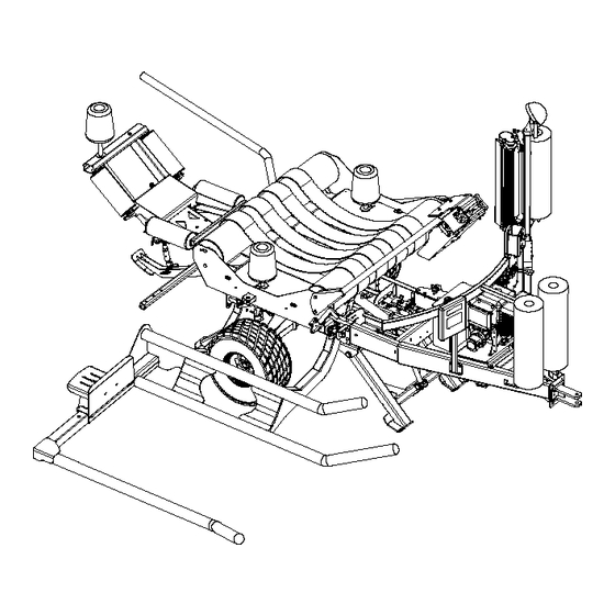
3 General Characteristics and Specifications Congratulations! You are now the ow ner o f a n AND ERSON bal e wrapper, a hi gh-quality machine designed for the separate storage of round bales of up to 5 f eet (1.5m) in diameter. This agricultural machine is carefully manufactured by our company to give you many years of reliable performance. -
Page 17: General Specifications
General Specifications Figure 3.2 Exterior dimensions for the base model Figure 3.3 Exterior dimensions for model with optional Dimensions and Weight Dimensions and Weight for model with optional for base model 140 po Length (A) Length (D) 187,50 po (4,77m) (3,55m) 89 po Width (B) -
Page 18: Adjustment Procedures
4 Adjustment Procedures Verifications Before Each Use Check the level hydraulic oil in the tank of your unit. Check the oil level in the Honda engine, if applicable, as w ell as the need for fu el. Open the fuel valve and check the engine air filter. If necessary, lubricate the machine well after each day of use. -
Page 19: Testing The Plastic Film Stretcher
Follow the diagram (Figure 4.2) to unro ll the start of the film between the rubber ro ller and an aluminium ro ller, t hen arou nd the o ther al uminium ro ller. Open the fi lm cutter wit h the lever and place it at the edge of the film. -
Page 20: Adjusting The Plastic Film Cutter
Adjusting the Plastic Film Cutter First c heck the condition o f the stain less s teel blade (1) in the diagram of (Figure 4.4) and change it as necessary. Figure 4.4 Plastic film cutter blade Additionally, by pushing the pl astic in the direction of the blade, the fingers normally push the rubber stopper to the adjustment bolt in the back . -
Page 21: Operating Procedures
5 Operating Procedures 5.1 Moving the Bale Wrapper Short and Medium Distances Your machine can be moved short and medium distances behind a tractor. Fasten the turntable latch (Figure 2.1). Attach the machine and attach a security chain to the ring provided for this purpose o n the draw bar. -
Page 22: First Start-Up Of A New Machine
To st art up the TAC-08C rec eiver, pull the red POWER knob. This can also serve as an emergency stop if you push on it. The bl ue “WRAPPING” button underneath wi ll start blinking to indicate that the machine is ready to be aligned. To s tart up y our T AC-08 rem ote co ntrol, p ush the b lack b utton o n the b ottom lef t. -
Page 23: Figure 5.2 Interior Of Tac-08C Receiver
Operation mode Fuse Fuse (2) Figure 5.2 Interior of TAC-08C receiver... -
Page 24: Aligning Your Bale Wrapper
Aligning Your Bale Wrapper Each tim e you p ull the P OWER b utton t o act ivate your re ceiver and your remo te con trol is – Alignment. activated, your remote control will be in [MENU #4] If you have the hydraulic unit, you will first be in [MENU #5] to start your engine, and then you will automatically move on to Alignment. - Page 25 The only difference between this menu and MENUs 1 and 3 is line 2 of the central window. Button #1 to access the following menu MENU 2 Button #2 Δ Shows the number of revolutions performed / the number of revolutions desired Rev: 00 / 18 Bal / (Y): 0 0 0 Shows the number of bales wrapped in the year...
-
Page 26: Menus Mode Error Messages
MENUS Mode Error Messages In all the MENUS, certain error messages may a ppear in t he central window during operation. For example, if the machine refuses to start or to function, you might see: [Out of range] The search for the wrapper during start-up fa iled. The re ceiver is turned off or too far away or your remote control is not associated. -
Page 27: Figure 5.3 Turntable Gear
Gear and encoder Hole Zero setting sensor Figure 5.3 Turntable gear [Unloading sensor error / Unloading] This sensor is located near the right axle and limits the rise and fall of the unloading table. It senses the presence of a lower hole when the table is lowered and an upper h ole when the table is raised (Figure 5.4). -
Page 28: Unloading Jam
Figure 5.4 Unloading sensor error [Other messages] If you use the emergency stop, you will see [emergency stop]. If you install the charger, you will see [Charging battery] or [Charging finished]. Unloading Jam Warning: If your table is not perfectly straight during unloading, a mechanical lock on prevent it from ti pping. -
Page 29: Adjustments Mode Of The Tac-08 Computer
Adjustments Mode of the TAC-08 Computer To switch from MENUS mode to programming adjustment mode (or vice-versa), simultaneously press the buttons [+] and [-], then release. ADJUSTMENT 1: Maximum number of revolutions to wrap a bale Change the number as necessary with button 3 or button 4 according to the instructions given in the wi ndows. -
Page 30: Start And End Wrapping
5.3 Start and End Wrapping Start If you do not use the optional hydraulic unit, adjust your tractor at a flow ra te of 8 GPM at 2000 PSI. Make sure your bale counter has been properly programmed. WARNING ! Once the tab le’s latc h has b een removed, u se th e lever s to l ower the rear (1 ) and front (2 ) stabilizers ( Figure 5 .5), if ap plicable. -
Page 31: Levers (Figure 5.5)
Levers (Figure 5.5) Note: The table levers (tab le ro tation (4), un loading (5), and pl astic film cu tter) (3) can be controlled manually to test the machine or to finish wrapping in case of a major electrical problem. -
Page 32: Maintenance Procedures
Warning ! Grease Gun Lubrication Your ANDERSON bale wrapper must be lubricated with a grease gun in the places indicated by the sticker (Figure 6.1). Figure 6.1 Grease gun lubrication Note: The use of synthetic grease is highly recommended... - Page 33 Central axle of turntable (1 on the top) Pivots of tilting table (2)* Axles of the tilting cylinder...
- Page 34 Axles of the unloading platform cylinder (2)* Pivot of the unloading arm (2)* Axles of the unloading arm cylinder (2)*...
- Page 35 Pivot of the unloading platform (4)* Front and rear stabilizers (2 grease cups each) and cylinder axles (2each)* Bearings of the two feed rollers of the belts (1 on each end, total of 4)
-
Page 36: Other Lubrication Points
Other Lubrication Points The p ower transmission cha ins and ot her m oving part s o f the mac hine must be o iled or greased regularly or every 50 hours. This also applies to the 2 toothed wheels of the plastic film stretcher. -
Page 37: Cleaning And Other Maintenance
Cleaning and Other Maintenance Pay particular attention to the cleanliness of the plastic film cutter system. An accumulation of debris (hay, dust, string, etc.) can reduce its functionality. Regularly check the cutting condition of the blade. Always keep the rollers and the gears of the plastic film stretcher free of a ll residue to p revent these p arts from jam ming, b reaking, or tearing the p lastic film. -
Page 38: Troubleshooting: Problems And Solutions
7 Troubleshooting: Problems and Solutions Before cal ling a tech nician, exa mine yo ur m achine and co nsult the tab le b elow to find a solution. Attempt to i solate the problem to find out if it is a hyd raulic or electrical problem by using the manual functions on the hydraulic valve. - Page 39 Make sure you have 12 V by The battery is too weak recharging or changing the battery. 4. Table alignment cannot be performed. Check the electrical connections (connectors on the hydraulic valves). Defective electrical connections See alignment procedure p. 22 and (Figure 7.3) Check for oil leaks and breaks.
-
Page 40: Reset Procedure
Reset Procedure If a p roblem arises during operation and you determine that the problem is with the electrical system, the f irst step to take i s to perform a com plete reset of the TAC-09C receiver. See t he following procedure: Turn o ff th e re ceiver (TAC-08C ) by pushing the red butto n o n the fr ont o f the... -
Page 41: Figure 7.2 Starter Fuse
Fuse Figure 7.2 Starter fuse Connections Figure 7.3 Electrical connections... -
Page 42: Optional Equipment
8 Optional Equipment Stabilizers Activated by hydraulic cylinders and controlled by manual controls at the front of the machine, these two pieces of equipmen t improve the stab ility of the bale wrapper. They a re equi pped with s ecurity valves (lo ck va lves) to p revent i nadvertent mo vement of s tabilizers or the fee t from co llapsing, whether t he machi ne is t urned on or not. -
Page 43: Installing The Bale Loading Arm Control
To transport the wrapper equipped with a loading arm, install the safety pin (1) that keeps he loading arm upright. WARNING! Figure 8.2 Bale Loading Arm Installing the Bale Loading Arm Control For the connections, refer to the parts book in section (electrical diagram of loading arm). Look at t he f ollowing ill ustrations to place t he c onnections. -
Page 44: Figure 8.4 Controller Connection
Figure 8.4 Controller connection Figure 8.5 Valve connection Figure 8.6 Controller support... -
Page 45: Figure 8.7 Bale Unloading Platform D
Bale Unloading Platform (D) Figure 8.7 Bale unloading platform D This op tional un loading ram p m akes i t p ossible to gent ly discharge wrapped bales behind the bale wrapper. This system is composed of a ri gid pl atform, a hy draulic cylinder, and a maintenance-free nitrogen cylinder. - Page 46 Additionally, this unl oading p latform mak es it po ssible to turn bales on one sid e or the ot her according to the preference of the user. To make this change, the operator need only place the barrier (6) on to p of the pla tform, the foot (4), the support roller (1), and the retaining bar (5) on the other side of th e unloading platform.
- Page 47 Attaching the retaining arm on the support Install the support of the arm. Place the support on the dumping unit and bolt into place. Holes on the dumper are predrilled from the factory. Installation of the retaining arm Insert the fixed part of the arm into the support.
- Page 48 You can now attach the ‘’L’’ shaped bar to the straight bar. (4 bolts) Installation of the cone shaped roller Remove the deflector at the end of the dumper to reveal the placement holes for the cone shaped roller. Place the cone shaped roller on the same side as the foot as you will be bumping the bale to the opposite side.
-
Page 49: Figure 8.9 Accumulator Of The Unloading Arm
This procedure is for if you are dropping the bale to the left side. The same procedure is used when dumping to the right side but the foot and cone roller will be placed on the other side of the machine. Also the ‘’L ‘’ shaped retaining arm must be inserted opposite to the procedure. Charging the accumulator When the unloading platform does not go back to its position, you must correct the pressure in the accumulator to a pres sure ra nging from 1000 t o 1200 l bs. -
Page 50: Double Roll Plastic Unit
Double Roll Plastic Unit The d ouble ro ll option a llows to in stall two p lastic film ro lls o n the p lastic film r oll s tretcher, thereby m aking it p ossible to ap ply a d ouble lay er of p lastic w ith each ro tation of t he tab le. With th is op tion, wrapping time will be decrease by almost half, b ecause two layers of p lastic are applied simultaneously Figure 8.10 Double stretch roll... -
Page 51: Start-Up Procedures
Start-Up Procedures When you receive your new ANDERSON equipment: Stationary mode: 1- Attach the b ale wrapper to th e t ractor or s tabilize the m achine with the stabilizers an d start the engine HONDA. 2- Activate t he recei ver by pull ing the red but ton. The blue ligh t o n the receiv er case will blink. - Page 52 Install a p lastic film roll (Figure 4.1). Insert the e dge of the p lastic film in th e clamp of the plastic film cutter. Pull the corresponding lever to hold the film (Figure 5.5) (Note: if you perf orm a wrapping t est w ithout a bale (d ry run), ens ure that the pl astic film detector is deactivated (see adjustment 5) (P.27).
- Page 53 Parts manual ROUND BALE WRAPPER RB680 ALWAYS KEEP THIS MANUAL WITH THE WRAPPER...
- Page 55 P. 36 For any parts order, please use the parts manual to find the item(s) you need and contact your dealer to order it or contact us directly at : ANDERSON GROUP 5125 de la Plaisance Chesterville (Québec) CANADA G0P 1J0...
- Page 56 BOLT 500044 BOLT 451172 HYDRAULIC FITTING 451355 HYDRAULIC FITTING 466989 VALVE 451260 HYDRAULIC FITTING 451171 HYDRAULIC FITTING 450972 HYDRAULIC FITTING 451261 HYDRAULIC FITTING 501057 HALF NYLON NUT Anderson Group, 5125 de la Plaisance Chesterville (Québec) G0P 1J0 Email : service@grpanderson.com...
- Page 57 FLANGE NUT TONGUE PARTS LIST ITEM PART DESCRIPTION 223077-1 TONGUE 500084 BOLT 322457 JACK 451355 HYDRAULIC FITTING 465903 VALVE 451179 HYDRAULIC FITTING 451265 HYDRAULIC FITTING 500017 BOLT Anderson Group, 5125 de la Plaisance Chesterville (Québec) G0P 1J0 Email : service@grpanderson.com...
-
Page 58: Axle
TIRE AND RIM PARTS LIST ITEM PART DESCRIPTION 481400 303035 BEARING 303036 BEARING 303037 ROLLING BEARING CAGE 303034 BEARING 303077 SEAL 481000 DUST CAP 507010 WHEEL BOLT Anderson Group, 5125 de la Plaisance Chesterville (Québec) G0P 1J0 Email : service@grpanderson.com... -
Page 59: Roll, Shield, And Valve
4 - ROLL, SHIELD, VALVE PARTS LIST ITEM PART DESCRIPTION 223026 ROLL AXLE 320006 RETAINING RING 320039 HITCH PIN 325107 224027 SUPPORT ROLLER 303045 BEARING Anderson Group, 5125 de la Plaisance Chesterville (Québec) G0P 1J0 Email : service@grpanderson.com... - Page 60 HYDRAULIC VALVE AND FITTING 315002 RECEIVER 315017 TRANSMITTER 209604 INSULATER 507029 SCREW 500050 BOLT 481009 PLASTIC CAP 223192 FILTER SUPPORT SEE NEXT PAGE HIGH PRESSURE FILTER AND FITTING Anderson Group, 5125 de la Plaisance Chesterville (Québec) G0P 1J0 Email : service@grpanderson.com...
- Page 61 HYDRAULIC FITTING 450972 HYDRAULIC FITTING 450711 HYDRAULIC FITTING 465883 CHECK VALVE 450994 HYDRAULIC FITTING 465504 VALVE 450542 HYDRAULIC FITTING 451355 HYDRAULIC FITTING 465913 CHECK VALVE 680-WITHOUT STABILIZER Anderson Group, 5125 de la Plaisance Chesterville (Québec) G0P 1J0 Email : service@grpanderson.com...
- Page 62 HYDRAULIC FITTING 450973 HYDRAULIC FITTING 450994 HYDRAULIC FITTING 450542 HYDRAULIC FITTING 450972 HYDRAULIC FITTING 450711 HYDRAULIC FITTING 465883 CHECK VALVE 465504 VALVE 465913 CHECK VALVE 680-WITH STABILIZER Anderson Group, 5125 de la Plaisance Chesterville (Québec) G0P 1J0 Email : service@grpanderson.com...
- Page 63 HYDRAULIC FITTING 450711 HYDRAULIC FITTING 465883 CHECK VALVE 450994 HYDRAULIC FITTING 465504 VALVE 450542 HYDRAULIC FITTING 451355 HYDRAULIC FITTING 465913 CHECK VALVE 465921 ELECTRIC VALVE 680-WITH LOADING ARM Anderson Group, 5125 de la Plaisance Chesterville (Québec) G0P 1J0 Email : service@grpanderson.com...
- Page 64 451126 HYDRAULIC FITTING 450008 HYDRAULIC FITTING 450243 HYDRAULIC FITTING 450716 HYDRAULIC FITTING 450024 HYDRAULIC FITTING 470010 PRESSURE GAUGE 469995 CATRIDGE 470018 FILTER 500084 BOLT 502045 LOCK WASHER Anderson Group, 5125 de la Plaisance Chesterville (Québec) G0P 1J0 Email : service@grpanderson.com...
-
Page 65: Stretcher Support
5 - STRETCHER SUPPORT PARTS LIST ITEM PART DESCRIPTION 223067 500502 CARRIAGE BOLT 223068 REINFORCMENT 500442 CARRIAGE BOLT 320021 LOCK 501032 NYLON NUT 501024 FLANGE NUT 500099 BOLT Anderson Group, 5125 de la Plaisance Chesterville (Québec) G0P 1J0 Email : service@grpanderson.com... - Page 66 SPRING 224081 BRAKE TEFLON 304009 SPRING 502001 FLAT WASHER 320002 501036 NYLON NUT 507036 ALLEN SET SCREW 224082 ROLLER SUPPORT 303012 BEARING 319880 WORK LIGHT 500289 BOLT Anderson Group, 5125 de la Plaisance Chesterville (Québec) G0P 1J0 Email : service@grpanderson.com...
-
Page 67: Stretcher
FLANGE NUT 322299 GREASE FITTING 315056 SENSOR 501022 FLANGE NUT 303018 BEARING 315007 SENSOR NUT 502080 LOCK WASHER 279004 ROLL 279103 GEAR 279104 GEAR DETAIL A DETAIL B Anderson Group, 5125 de la Plaisance Chesterville (Québec) G0P 1J0 Email : service@grpanderson.com... -
Page 68: Power Unit
PUMP ADAPTER 451190 HYDRAULIC FITTING 224108 TANK 470990 STRAINER 470117 PLUG 450725 HYDRAULIC FITTING 450717 HYDRAULIC FITTING 500092 BOLT 501022 FLANGE NUT 501020 FLANGE NUT 500004 BOLT Anderson Group, 5125 de la Plaisance Chesterville (Québec) G0P 1J0 Email : service@grpanderson.com... -
Page 69: Dumping Table
HITCH PIN 315020-1 ENCODER 501037 NYLON NUT 223169 500084 ENCODER POSITIONER BOLT 223086 GEAR 502045 LOCK WASHER 507005 ALLEN SET SCREW 222053 SHUTTER 300513 GEAR 500333 BOLT Anderson Group, 5125 de la Plaisance Chesterville (Québec) G0P 1J0 Email : service@grpanderson.com... - Page 70 9 - DUMPING TABLE PARTS LIST ITEM PART DESCRIPTION 450712 HYDRAULIC FITTING 467029 HYDRAULIC CYLINDER 450543 HYDRAULIC FITTING 465878 CHECK VALVE 322295 GREASE FITTING Anderson Group, 5125 de la Plaisance Chesterville (Québec) G0P 1J0 Email : service@grpanderson.com...
-
Page 71: Rotary Table
NYLON NUT 500004 BOLT 303024 325145 BEARING SECURITY TRIANGLE 500246 BOLT 501032 NYLON NUT 223039 DRIVING ROLLER 500440 CARRIAGE BOLT 223040 TRACTED ROLLER 222055 SUPPORT 223049 SUPPORT ROLLER Anderson Group, 5125 de la Plaisance Chesterville (Québec) G0P 1J0 Email : service@grpanderson.com... -
Page 72: Cut And Hold
HYDRAULIC FITTING 500442 CARRIAGE BOLT 467000 HYDRAULIC CYLINDER 501022 FLANGE NUT 320044 COTTER PIN 224054 501032 SIDE PLATE NYLON NUT 500004 BOLT 502044 LOCK WASHER 224055 SIDE PLATE Anderson Group, 5125 de la Plaisance Chesterville (Québec) G0P 1J0 Email : service@grpanderson.com... -
Page 73: Central Hub
NYLON NUT 500004 BOLT 223020 WASHER 300509-S MITTER GEAR 224189 WASHER 501076 CASTLE NUT 206802 320020 COTTER PIN 303989 BEARING 500175-1 BOLT 501044-1 STOVER LOCK NUT 500179 BOLT Anderson Group, 5125 de la Plaisance Chesterville (Québec) G0P 1J0 Email : service@grpanderson.com... -
Page 74: Loading Arm
FLAT WASHER 500088 BOLT 501032 NYLON NUT 322299 GREASE FITTING 223087-1 223055 LOCK 223056 BALE STOPPER 500501 CARRIAGE BOLT 501024 FLANGE NUT 223057-1 LOADING ARM FRAME 303051 BUSHING Anderson Group, 5125 de la Plaisance Chesterville (Québec) G0P 1J0 Email : service@grpanderson.com... - Page 75 SNAP RING 223099 WASHER 450712M HYDRAULIC FITTING PARTS LIST ITEM PART DESCRIPTION 501024 FLANGE NUT 500501 CARRIAGE BOLT 500173 BOLT 502048 LOCK WASHER 223083 COUNTERWEIGHT 223082 SUPPORT Anderson Group, 5125 de la Plaisance Chesterville (Québec) G0P 1J0 Email : service@grpanderson.com...
- Page 76 ITEM PART DESCRIPTION 223063 FRONT ATTACMENT 223066 500502 CARRIAGE BOLT 502004 FLAT WASHER LEVER 223065 223064 SPACER 501024 FLANGE NUT 500096 BOLT 501032 NYLON NUT 500088 BOLT Anderson Group, 5125 de la Plaisance Chesterville (Québec) G0P 1J0 Email : service@grpanderson.com...
-
Page 77: Stabilizer
REAR STABILIZER SUPPORT 501024 FLANGE NUT 500500 CARRIAGE BOLT 467026 CYLINDER 500330 BOLT 450712 HYDRAULIC FITTING 322295 GREASE FITTING 223173-1 STABILIZER SUPPORT 223304 ATTACHMENT 320043 COTTER PIN Anderson Group, 5125 de la Plaisance Chesterville (Québec) G0P 1J0 Email : service@grpanderson.com... -
Page 80: Drop Off
GREASE FITTING 223183 FIXED PART OF ARM 223184 REMOVABLE PART OF ARM 223186-1 OUTRIGGER 223187 ROLLER SUPPORT AXLE 325107 325112 ROLLER SUPPORT 303045 BEARING 320006 RETAINING RING Groupe Anderson, 5125 de la Plaisance Chesterville (Québec) G0P 1J0 Email : service@grpanderson.com... -
Page 89: Loading Arm Electrical Diagram
YELLOW PARTS LIST ITEM PART DESCRIPTION 315079 315057 SWITCH 225114 SWITCH SUPPORT 322620 STRAP VALVE 465921 315114 MALE CONNECTOR 315113 FEMALE CONNECTOR 470113 BATTERY 315118 FUSE HOLDER Groupe Anderson, 5125 de la Plaisance Chesterville (Québec) G0P 1J0 Email : service@grpanderson.com...
Need help?
Do you have a question about the RB 680 and is the answer not in the manual?
Questions and answers