Table of Contents
Advertisement
Advertisement
Chapters
Table of Contents
Troubleshooting

Related Manuals for Anderson ROUND BALE WRAPPER HYBRID


Summary of Contents for Anderson ROUND BALE WRAPPER HYBRID
- Page 1 #404606-3 Round and Square Bale Wrapper HYBRID Operator’s Manual 2011...
-
Page 3: Table Of Contents
Table of Contents 1 ANDERSON Limited Warranty ..................... 8 One-Year Limited Warranty ..................8 Documents ........................ 8 Problem Resolution ....................8 Modifications ......................8 Warranty Exemptions ....................10 Exclusive Remedy ....................10 2 Safety ..........................11 Safe Operators ......................11 Danger Zone ...................... - Page 4 Characteristics ......................42 Remote Control ......................42 Start Up ........................42 Programming ......................42 Malfunction ......................42 12.3 Anderson Plastic Detector ..................43 12.4 Remote steering ....................44 General characteristics ..................... 44 Receiver ........................44 Remote Control ......................45 start your engine with the remote control ..............45 Remote control / Control box association ..............
- Page 5 - Product model and serial number; - Purchase date and invoice number; - Dealer name, address, and telephone number and salesperson name; - Precise and detailed description of your problem. ANDERSON GROUP Address: 5125 de la Plaisance Chesterville (Québec) CANADA G0P 1J0 Email Service: service@grpanderson.com...
- Page 7 ANDERSON LIMITED WARRANTY FORM Warranty form must be completed and returned. Please fill in this form with information about your new machine. Please return this form to us in the 15 days following the date of delivery to validate your warranty. Details of the warranty provided can be found in the operator’s manual.
- Page 9 For your personal records, we recommend that you fill in this form with information about your machine. Type of Machine: Model: Options: Serial Number: Date of Sale to Customer: Customer Name: Customer Address: Customer Telephone Number: Dealer Name: Salesperson Name: Dealer Address: Salesperson Signature:...
-
Page 10: Anderson Limited Warranty
1 ANDERSON Limited Warranty One-Year Limited Warranty In the year following the purchase of a new machine, if your ANDERSON equipment fails to operate properly due to defective materials, manufacturing, or assembly, our company will furnish replacement parts and repair your machine free of charge. - Page 11 For all repair requests made to an Anderson dealer, you must furnish the date of sale, the serial number, the type of equipment and options, and the owner’s contact information.
-
Page 12: Warranty Exemptions
Except for conditions or warranties which may not be excluded by law, the selling dealer makes no warranty of its own on any item warranted by Anderson Equipment unless it delivers to the purchaser a separate written warranty document specifically warranting the item. The... -
Page 13: Safety
2 Safety Your ANDERSON bale wrapper was designed to function very safely. However, some of its components, including the gasoline engine, the hydraulic system, and rapidly moving parts, can cause serious accidents. Read and follow attentively the safety advice that follows. -
Page 14: Hydraulic Oil
Hydraulic Oil Any leak of pressurized oil can cause serious injuries. Do not use your hands to locate a leak, but rather an object such as a piece of cardboard. Stop the engine and release the pressure before disconnecting or reconnecting the lines. Firmly tighten all connections before restarting the engine or reapplying hydraulic pressure. -
Page 15: General Characteristics And Specifications
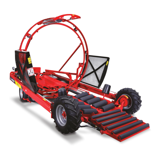
3 General Characteristics and Specifications Congratulations! You are now the owner of an ANDERSON bale wrapper, a high-quality machine designed for inline continuous wrapping of large round and square bales. This agricultural machine is carefully manufactured by our company to give you many years of reliable performance. -
Page 16: Moving The Bale Wrapper
4 Moving the Bale Wrapper Short Distances Your bale wrapper can be moved very short distances using its own traction. Start the engine and use the control levers (Figure 4.1). (There are 4 ways to start the HONDA engine: manual ignition, electronic ignition with key, electronic ignition with remote control, and electronic ignition using the same remote control as for remote steering.) Figure 4.1 Controls... -
Page 17: Medium Distances
Medium Distances Your machine can be moved short and medium distances behind a tractor or truck. Use the hydraulic jack to raise the front of the bale wrapper. Attach the machine and attach a security chain to the ring provided for this purpose on the draw bar (Figure 4.3). The front wheels of the machine should not touch the ground during transportation. -
Page 18: Advice For Producing High Quality Fodder Silage
40% less than for individual bale wrapping or bagging, all while creating the same airtight conditions necessary for high-quality silage. The savings that the ANDERSON bale wrapper will produce is an important addition to all the advantages mentioned above. -
Page 19: When Is The Best Time For Baling
When Is the Best Time for Baling? After the drying period, the decision of when to bale your fodder depends above all on the time when the amount of humidity in the cut hay has decreased just enough. If you want your fodder to stay good for at least a year, the ideal level of humidity is around 50% for both grasses and legumes, with a possible range of 40% to 55%. -
Page 20: Beginning Continuous Bale Wrapping
6 Beginning Continuous Bale Wrapping Before Beginning Check the level of oil in the hydraulic tank, as well as the level of fuel in the tank of the Honda engine. Also check the Honda engine’s oil level using the gauge at the base behind the engine (Figure 6.1). - Page 21 Figure 6.3 Roll support and stretcher Next, follow the diagram (the same diagram as is on the machine) (Figure 6.4) to thread the film, first behind the black rubber free roller, then through the 2 aluminum rollers of the plastic film stretcher.
-
Page 22: Installing The 2 Plastic Film Roll
Installing the 2 Plastic Film Roll Release the brake of the hoop wheel, turn the hoop 180 degrees, and reengage the brake. Repeat the preceding installation instructions. Put the screen back in place and do not forget to release the hoop brake before starting the engine. Leaving the plastic rolls in the sun for an extended period of time before installation can cause the film to become soft. - Page 23 ROUND BALE SQUARE BALE Figure 6.5 Round or square bale position 1 Figure 6.6 Round or square bale position 2 ROUND BALE POSITION SQUARE BALE POSITION ADJUSTMENT 2 ADJUSTMENT 3 ADJUSTMENT 1 Figure 6.7 Round or square bale position 3...
- Page 24 Figure 6.8 Round or square bale position 4 Figure 6.9 Round or square bale position 5 Figure 6.10 Round or square bale position 6 Bring your bale wrapper to your chosen location. Remove the draw bar from the machine and store it in the support on the front right side of the machine.
-
Page 25: Getting Started In 4 Steps
Getting Started in 4 Steps There are several good ways to begin a continuous bale row. Here is the method that we recommend: Level Position Use the hydraulic lever to raise the front of the bale wrapper to the horizontal position so that the first bales that you place on the machine do not slide forward. -
Page 26: Wrapping Settings
7 Wrapping Settings Adjusting automatic system You already know that it is possible to increase the number of plastic film layers by moving the wrapping speed control lever to a higher number. Remember that each full revolution of the hoop represents two layers of plastic film due to the two plastic film stretchers. On the other hand, you may simply want to add one or two additional layers where the separate bales meet in order to have a more airtight and more solid continuous bale row without adding extra plastic film everywhere. -
Page 27: Deactivation Of The Pusher System
Deactivation of the pusher system It is possible to deactivate the pusher trigger. Deactivating the trigger will allow you to activate only the hoop to replace the plastic even if there is a bale placed on the pusher mechanism. To deactivate the trigger, it is necessary to have the valve that is situated behind the wrapper near the hydraulic oil tank. -
Page 28: Adjusting The Hoop's Drive Wheel
Adjusting the Hoop’s Drive Wheel If the hoop slips or stops, you can increase the tension of the spring that holds the wheel in place. All you have to do is tighten the nut on the threaded rod, located above the spring to the left of the wheel (Figure 7.3). -
Page 29: Adjustment Procedures
8 Adjustment Procedures Factory-Made Automatic System: In Case of Problem Check Adjustments Follow steps (8.1)-(8.2)-(8.3)-(8.4)-(8.5). Refer to the numbers in the illustrations. Figure 8.1 Start pedal 8.1 Press down on the start pedal located at the back of the bale wrapper, right next to the Honda gasoline engine (Figure 8.1 #1). - Page 30 3/16’’ Figure 8.3 Gap 8.3 If the automatic system is correctly adjusted, you should obtain a distance of 3/16’’ (Figure 8.3 #4) between the snap ring and the body of the valve. If you do not obtain a distance of 3/16’’, refer to the adjustment procedure that follows. Figure 8.4 Transfer bar 8.4 ...
-
Page 31: Adjusting The Hoop Release
Adjusting the Hoop Release 8.6 Place the part (Figure 8.5 #10) at the 7 slot from the rear of the machine (Figure 8.5#11). Figure 8.5 Stopper 8.7 Place the hoop speed control lever at position 0 (Figure 8.6 #12). Press the hydraulic stop button (Figure 8.6 #13). - Page 32 the end of the pointer (Figure 8.7 #14). Stop the engine and adjust the actuator lever (Figure 8.7 #15) so that it skims the end of the pointer (Figure 8.7 #14). The automatic system is now adjusted. Restart the engine and pull the hydraulic stop button (Figure 8.6 #13) to make the pusher return to its starting position.
-
Page 33: Adjusting The Pusher Trigger
Adjusting the Pusher Trigger 8.9 Place the speed control lever at position 0 (Figure 8.6 #12). Push the hydraulic stop button (Figure 8.6 #13). Start the engine. Push down the pusher start pedal (Figure 8.1 #1). Stand so that you can see the trigger (Figure 8.9 #17) and the pusher cross bar (Figure 8.9 #18). -
Page 34: How To Finish A Continuous Bale Row
9 How to Finish a Continuous Bale Row Steps Wrap the last bale of the continuous bale row in a plastic bag and load it onto the bale wrapper. Do not forget to release the hydraulic brake Stop the engine (Do not stay or walk on the machine when the engine is running). -
Page 35: Variation For Finishing A Continuous Bale Row
Figure 9.3 Speed control lever Press down the pusher start pedal again to make the pusher complete 2-3 more pushing cycles. Keep the unloading posts in place until the second post has traveled almost as far as it can go and the last bale has been pushed to the end of the front gate. 10. -
Page 36: Maintenance And Storage
Safety During maintenance, it is important to respect all safety rules. Grease Gun Lubrication Your ANDERSON bale wrapper must be lubricated with a grease gun every 200 bales in the places indicated by a yellow sticker. Both front axels. Both rear axels. - Page 37 Figure 10.4 Swevel Your wrapper needs to be oiled after every 200 bales in the places indicated by the yellow stickers. Traction chain. Engine idle control. Automatic system. Hoop activation. Pusher guide rail. Figure 10.5 Traction chain. Figure 10.6 Engine idle control.
- Page 38 Figure 10.7 Automatic system. Figure 10.8 Hoop activator. Figure 10.9 Pusher guide rail. Pusher rail: Both square tubes that serve as guide rails were greased in the factory. The use of additional grease could accumulate dust and cause the pusher to slide badly. We recommend that you use some new oil to the places indicated with the yellow stickers, as well as on the rear part of the tubes when the pusher is moved toward the front of the Important !
-
Page 39: Cleaning
Cleaning Always keep the rollers of the plastic film stretcher and the rubber free roller clean and free of all hay or other residue to prevent these parts or the gears from jamming, breaking, or tearing the plastic film. Also remove regularly the hay that can get stuck in the axles and gears of the machine so as not to place needless strain on the hydraulic engines. -
Page 40: Troubleshooting
11 Troubleshooting Breakdown?!? You machine is functioning poorly or not at all?!? Before calling a technician, examine your machine and consult the table below to find a solution. If you are still not able to solve the problem yourself, ask for help from the customer service department of your agricultural dealer. - Page 41 Move the control forward between The hoop speed control is at 0. 2 and 10. Tighten the wheel spring. Check tire air pressure and adjust The drive wheel slides on the hoop. if necessary. Change the tire if it is worn out. Check oil level.
- Page 42 The 12 V battery of the remote Change the battery or check the control has lost its charge or is connection. Next, press in disconnected. alternation on the right/left 11. The remote control direction buttons to reprogram for remote operation remote operation.
-
Page 43: Optional Equipment
12 OPTIONAL EQUIPMENT 12.1 Work Lights Two halogen lights installed on the cross bar on the right side of the machine to facilitate machine operation in the evening or at night. Connected to the machine’s electrical system (Figure 12.1)(Figure 12.2). Be aware that the Honda engine must be equipped with a minimum 10 amp alternator for this option to be successfully installed. -
Page 44: Remote Starter
12.2 Remote Starter Characteristics This electric starter system, also called an engine kill, can only start or stop the Honda gas engine. It includes a module that is installed on the interior of the rear chassis on the right side and connected to the engine. -
Page 45: Anderson Plastic Detector
12.3 Anderson Plastic Detector This equipment can be added to the Anderson NWX660 bale wrapper. It stops the machine when the plastic film tears or runs out. To activate or deactivate the plastic watch, move the pin into the desired hole of the rod just above the control panel of the wrapper. -
Page 46: Remote Steering
12.4 Remote steering General characteristics The remote steering option allows the operator to control the wrapper from his tractor. functions of the remote permit the operator to move the wrapper and also start and stop the Honda engine. The direction can be controlled with the remote control or with the control levers on the main valve. -
Page 47: Remote Control
Remote Control Each remote control is equipped with three alkaline batteries (AA). They are located in the compartment under the remote control. The below diagram shows the functions of the remote control. FONCTION Turn to the left Turn to the right Select manual or automatic(*) Selection for... -
Page 48: Remote Control / Control Box Association
Remote control / Control box association In the case of a lost or broken remote control, you will have to replace it. The new remote control must be associated with the receiver (Control box). The following procedure allows you to make the association. Remove the Honda engine key. -
Page 49: Trouble Shooting
Trouble shooting Problem Possible Cause Solution battery completely Verify the charge of the The system does not uncharged. batteries replace work after start up. necessary. The receiver is not turned on. Verify the Adress Learn LED to insure that it is on. Verify connections. -
Page 50: Diesel Engine
12.5 Diesel engine The NWX660 is also available with a diesel engine manufactured by KUBOTA. This option allows you to use a pump with a larger flow (debit) which will increase the performance of the machine. The operator’s manual specific to the diesel engine is supplied with the wrapper. -
Page 51: Hoop
13 Hoop 13.1 Reassembling the Hoop Outer Hoop Place the 4 sections flat on the ground. Place a 3/8” wide metal spacer on the ground in the center of each section so that the sections are parallel to the ground. Each end piece is numbered from 1 to 4. -
Page 52: Reassembly Instructions For Revolving Hoop
Reinstall the 5 rollers. 13.2 Reassembly Instructions for Revolving Hoop You have received your machine assembled in the factory according to the illustration below (Figure 13.3) and you want to reinstall the hoop in normal position. Here are the steps to follow: 1 –... - Page 53 Parts manual ROUND BALE WRAPPER HYBRID ALWAYS KEEP THIS MANUAL WITH THE WRAPPER 24 novembre 2010...
- Page 55 Content 1 – General view P. 4 2 – Complete front section P. 5 3 – Frame front section P. 6 4 – Front gate P. 8 5 – Table P. 9 6 – Front spindle P. 10 7 – Support roller – Table support P.
- Page 56 36 – TANK P. 58 For any parts order, please use the parts manual to find the item(s) you need and contact your dealer to order it. ANDERSON EQUIPMENT 5125 de la Plaisance Chesterville (Québec) CANADA G0P 1J0 Fax :...
-
Page 58: General View
Hydraulic jack Tow bar (hold on place) Moteur Honda et batterie Honda engine and battery Frein et roue d'entraînement du cerceau Brake and wheel drive for the hoop Anderson Group, 5125 de la Plaisance Chesterville (Québec) G0P 1J0 Email : service@grpanderson.com... -
Page 59: Complete Front Section
320002 COTTER PIN 467501 HAIR PIN 467502 CYLINDER PIN 450543 HYDRAULIC FITTING 210504-1 TABLE LOCK 450712 HYDRAULIC FITTING 210506-1 COMPLETE TABLE 467228 HYDRAULIC CYLINDER 320031 LOCK PIN Anderson Group, 5125 de la Plaisance Chesterville (Québec) G0P 1J0 Email : service@grpanderson.com... - Page 60 3 - FRONT FRAME SECTION DETAIL B DETAIL A Anderson Group, 5125 de la Plaisance Chesterville (Québec) G0P 1J0 Email : service@grpanderson.com...
- Page 61 501036 NYLON NUT 500285 BOLT 451173 HYDRAULIC FITTING 320082 TOW BAR LOCKING PIN 320039 HITCH PIN 481503 FRONT TIRE AND RIM 500509 CARRIAGE BOLT 500602 FLANGE BOLT Anderson Group, 5125 de la Plaisance Chesterville (Québec) G0P 1J0 Email : service@grpanderson.com...
-
Page 62: Front Gate
FRONT GATE ROLLER 210518-1 FRONT GATE FRAME 210519-3 SMALL ROLLER LOCK 501020 FLANGE NUT 500361 CARRIAGE BOLT 210519-2 MEDIUM ROLLER LOCK 500362 CARRIAGE BOLT 210519-1 LONG ROLLER LOCK Anderson Group, 5125 de la Plaisance Chesterville (Québec) G0P 1J0 Email : service@grpanderson.com... -
Page 63: Table
CENTER ROLLER SUPPORT 501035 NYLON NUT 500246 BOLT 507039 SELF-DRILLING SCREW 304011 SPRING 210788 STEEL CABLE 450541 HYDRAULIC FITTING 450897 HYDRAULIC FITTING 452224 HYDRAULIC FITTING DETAIL B DETAIL A Anderson Group, 5125 de la Plaisance Chesterville (Québec) G0P 1J0 Email : service@grpanderson.com... - Page 64 HUB WITH SPROCKET 507016 WHEEL BOLT 320002 COTTER PIN 502011 FLAT WASHER 303501 CONIC BEARING 303099 BEARING CUP 303034 CONIC BEARING 303037 BEARING CUP 481503 TIRE AND WHEEL RIM Anderson Group, 5125 de la Plaisance Chesterville (Québec) G0P 1J0 Email : service@grpanderson.com...
-
Page 65: Support Roller-Table Support
500289 BOLT Table support PARTS LIST ITEM PART DESCRIPTION 325112 SUPPORT ROLLER 303045 BEARING 320006 RETAINING RING 320010 HITCH PIN 210526 SUPPORT ROLLER SHAFT 325107 Support roller Anderson Group, 5125 de la Plaisance Chesterville (Québec) G0P 1J0 Email : service@grpanderson.com... -
Page 66: Rear Section
COMPLETE LEFT SHIELD NEXT PAGE COMPLETE HOOP NEXT PAGE RIGHT SIDE FRAME FOR HOOP 467289 HYDRAULIC CYLINDER 210535 PUSH OF POLE WITH SHAFT 210534-1 PUSH OF POLE WITH LOCK Anderson Group, 5125 de la Plaisance Chesterville (Québec) G0P 1J0 Email : service@grpanderson.com... -
Page 67: Fender
CARRIAGE BOLT RIGHT 501022 FLANGE NUT 500500 CARRIAGE BOLT 501024 FLANGE NUT 501032 NYLON NUT 210541 FRONT RIGHT FENDER 210543 REAR RIGHT FENDER 210538-1 JOINT RIGHT LEFT Anderson Group, 5125 de la Plaisance Chesterville (Québec) G0P 1J0 Email : service@grpanderson.com... -
Page 68: Transversal Hoop Bar
10 - RIGHT TRANSVERSAL HOOP BAR Anderson Group, 5125 de la Plaisance Chesterville (Québec) G0P 1J0 Email : service@grpanderson.com... - Page 69 SEE OTHER PAGE 500092 BOLT 500016 BOLT SEE OTHER PAGE 315080 BALE COUNTER 210842 LIGHT SUPPORT 500086 BOLT 210891 EMERGENCY STOP SUPPORT 210138-2 EMERGENCY STOP 210549 SUPPORT DE VALVE Anderson Group, 5125 de la Plaisance Chesterville (Québec) G0P 1J0 Email : service@grpanderson.com...
- Page 70 LEFT TRANSVERSAL HOOP BAR 500500 CARRIAGE BOLT 501024 FLANGE NUT 500506 CARRIAGE BOLT 210759 LEFT SIDE BALE GUIDE 210760 BALE GUIDE LOCK 210761 BALE GUIDE 501032 NYLON NUT 500086 BOLT Anderson Group, 5125 de la Plaisance Chesterville (Québec) G0P 1J0 Email : service@grpanderson.com...
-
Page 71: Hydraulic Control
450543 HYDRAULIC FITTING 450242 HYDRAULIC FITTING 450542 HYDRAULIC FITTING 450994 HYDRAULIC FITTING 450022 HYDRAULIC FITTING 470010 PRESSURE GAUGE 450196 HYDRAULIC FITTING 450877 HYDRAULIC FITTING 465878 CHECK VALVE Anderson Group, 5125 de la Plaisance Chesterville (Québec) G0P 1J0 Email : service@grpanderson.com... - Page 72 PARTS LIST ITEM PART DESCRIPTION 465983 SPEED CONTROL VALVE 450712 HYDRAULIC FITTING 450716 HYDRAULIC FITTING 465879 CHECK VALVE 450548 HYDRAULIC FITTING 450381 HYDRAULIC FITTING 450008 HYDRAULIC FITTING Anderson Group, 5125 de la Plaisance Chesterville (Québec) G0P 1J0 Email : service@grpanderson.com...
- Page 73 HYDRAULIC FITTING 450972 HYDRAULIC FITTING 451227 HYDRAULIC FITTING 451123 HYDRAULIC FITTING 450877 HYDRAULIC FITTING 451355 HYDRAULIC FITTING 451265 HYDRAULIC FITTING 451313 HYDRAULIC FITTING VALVE ÉLECTRIQUE ELECTRIC VALVE Anderson Group, 5125 de la Plaisance Chesterville (Québec) G0P 1J0 Email : service@grpanderson.com...
-
Page 74: Bale Guide
NYLON NUT 501030 NYLON NUT 500017 BOLT 210763 ADJUSTABLE ARM 210764 RELEASE ARM 306030 CASTER 210843 SPACER 502006 FLAT WASHER 501024 FLANGE NUT 500179 BOLT DETAIL A Anderson Group, 5125 de la Plaisance Chesterville (Québec) G0P 1J0 Email : service@grpanderson.com... -
Page 75: Pusher Frame Side
13 - PUSHER FRAME SIDE PARTS LIST ITEM PART DESCRIPTION 210559-1 LEFT SIDE PUSHER FRAME 500500 CARRIAGE BOLT 501024 FLANGE NUT 210558-1 RIGHT SIDE PUSHER FRAME DETAIL B DETAIL A Anderson Group, 5125 de la Plaisance Chesterville (Québec) G0P 1J0 Email : service@grpanderson.com... -
Page 76: Pusher Support
14 - PUSHER SUPPORT DETAIL B DETAIL A Anderson Group, 5125 de la Plaisance Chesterville (Québec) G0P 1J0 Email : service@grpanderson.com... - Page 77 210791 JACK SUPPORT 306022 JACK AXLE 210566-2 COMPLETE PUSHER 501005 210816 STOPPER 210567-2 PUSHER PLATE 210830-4 LEFT PUSHER SUPPORT 500026 BOLT 501042 JAM NUT 306020 JACK AXLE Anderson Group, 5125 de la Plaisance Chesterville (Québec) G0P 1J0 Email : service@grpanderson.com...
-
Page 78: Pusher
SIDE FRAME SWIVEL HEART 500230 BOLT 210572-2 PUSHER FRAME 500501 CARRIAGE BOLT 501024 FLANGE NUT 500187 BOLT 501032 NYLON NUT 500100 BOLT 320023 LOCK PIN DETAIL B Anderson Group, 5125 de la Plaisance Chesterville (Québec) G0P 1J0 Email : service@grpanderson.com... - Page 79 DESCRIPTION 210576-1 INSIDE HOOP SECTION 500442 CARRIAGE BOLT 501022 FLANGE NUT 210836 BOTTOM HOOP ATTACHMENT 500500 CARRIAGE BOLT 501024 FLANGE NUT DETAIL H DETAIL J OUTSIDE HOOP Anderson Group, 5125 de la Plaisance Chesterville (Québec) G0P 1J0 Email : service@grpanderson.com...
- Page 80 PLASTIC ROLLER FIXED HOLDER 279004 COMPLETE STRETCHER 210585 RETAINING ROD 500044 BOLT 279005 BLACK ROLLER ON STRETCHER 210744 STRETCHER FRAME 500175 BOLT 500254 BOLT 501025 FLANGE NUT SEE OTHER PAGE Anderson Group, 5125 de la Plaisance Chesterville (Québec) G0P 1J0 Email : service@grpanderson.com...
- Page 81 16 - CASTER HOOP PARTS LIST ITEM PART DESCRIPTION 306014-1 HOOP CASTER 306019-1 SPACER 303021-2 BEARING Anderson Group, 5125 de la Plaisance Chesterville (Québec) G0P 1J0 Email : service@grpanderson.com...
-
Page 82: Stretcher
17 - STRETCHER RUBBER ROLLER STRETCHER Anderson Group, 5125 de la Plaisance Chesterville (Québec) G0P 1J0 Email : service@grpanderson.com... - Page 83 210589 COVER 501030 NYLON NUT 210590 WASHER 501022 FLANGE NUT 501020 FLANGE NUT 304005 SPRING 500004 BOLT 501000 500008 BOLT 500017 BOLT 303018 BEARING 224069 ALUMINIUM ROLL Anderson Group, 5125 de la Plaisance Chesterville (Québec) G0P 1J0 Email : service@grpanderson.com...
-
Page 84: Holder For Plastic Roll
279007 PLASTIC ROLL HOLDER 303012 BEARING 500006 BOLT 320039 HITCH PIN PARTS LIST ITEM PART DESCRIPTION 501036 NYLON NUT 320027 RETAINING RING 500293 BOLT 279007 303012 BEARING Anderson Group, 5125 de la Plaisance Chesterville (Québec) G0P 1J0 Email : service@grpanderson.com... -
Page 85: Hoop Shield
FIXED SHIELD ATTACHEMENT DETAIL E DETAIL D PARTS LIST ITEM PART DESCRIPTION 501020 FLANGE NUT 500006 BOLT 210755 SHIELD HANDLE 210809 SHIELD LOCK 500004 BOLT 304021 SPRING 210831 LOCK Anderson Group, 5125 de la Plaisance Chesterville (Québec) G0P 1J0 Email : service@grpanderson.com... -
Page 86: Rear Section
NEXT PAGES REMOVABLE SPEAR AND SUPPORT NEXT PAGES REAR BUMPER 210600 REINFORCMENT BEAM NEXT PAGES STEERING SYSTEM NEXT PAGES COMPLETE AUTOMATIC SYSTEM NEXT PAGES COMPLETE DRIVE WHEEL Anderson Group, 5125 de la Plaisance Chesterville (Québec) G0P 1J0 Email : service@grpanderson.com... -
Page 87: Support For Spear And Hoop
DESCRIPTION 210604 CENTRAL BEAM SUPPORT 500506 CARRIAGE BOLT 501024 FLANGE NUT 500510 CARRIAGE BOLT 210605 FRONT BALE GUIDE SUPPORT 320029-1 QR PIN 501034 NYLON NUT 500177 BOLT Anderson Group, 5125 de la Plaisance Chesterville (Québec) G0P 1J0 Email : service@grpanderson.com... -
Page 88: Support Hoop
NYLON NUT 210772 LEFT HOOP PIVOT 500510 CARRIAGE BOLT 210771 LEFT ATTACHMENT HOOP 320029-3 QR PIN 500500 CARRIAGE BOLT 210841 LEFT PIVOT PLATE 210208 LEFT PUSHER CYLINDER SUPPORT Anderson Group, 5125 de la Plaisance Chesterville (Québec) G0P 1J0 Email : service@grpanderson.com... - Page 89 500501 CARRIAGE BOLT 502006 FLAT WASHER 210769-1 RIGHT PIVOT PLATE 210770-1 ATTACHEMENT FOR RIGHT SHIELD 210207 RIGHT PUSHER CYLINDER SUPPORT 210892 HOSE ATTACHMENT 500006 BOLT 500082 BOLT Anderson Group, 5125 de la Plaisance Chesterville (Québec) G0P 1J0 Email : service@grpanderson.com...
-
Page 90: Central Beam
CARRIAGE BOLT 210773 MANIFOLD 450548 HYDRAULIC FITTING 450558 HYDRAULIC FITTING 450064 HYDRAULIC FITTING 501020 FLANGE NUT 500017 BOLT 450863 HYDRAULIC FITTING 450899 HYDRAULIC FITTING 450973 HYDRAULIC FITTING Anderson Group, 5125 de la Plaisance Chesterville (Québec) G0P 1J0 Email : service@grpanderson.com... -
Page 91: Spear
24 - SPEAR PARTS LIST ITEM PART DESCRIPTION 210619 SPEAR SUPPORT 320069 QR PIN 500510 CARRIAGE BOLT 501024 FLANGE NUT 210620-5 SPEAR Anderson Group, 5125 de la Plaisance Chesterville (Québec) G0P 1J0 Email : service@grpanderson.com... -
Page 92: Rear Bumper
25 - REAR BUMPER DETAIL A Anderson Group, 5125 de la Plaisance Chesterville (Québec) G0P 1J0 Email : service@grpanderson.com... - Page 93 210775-1 POST LOCK 320031 LOCK PIN 308011 320032-1 HITCH PIN 210758 TRIANGLE SUPPORT 325145 SLOW VEHICULE TRIANGLE 222055 SUPPORT TRIANGLE 500084 BOLT 500001 BOLT 500360 CARRIAGE BOLT Anderson Group, 5125 de la Plaisance Chesterville (Québec) G0P 1J0 Email : service@grpanderson.com...
-
Page 94: Steering Axle
210626 DIRECTION ANGLE ARM 467503 CYLINDER AXLE 467501 HAIR PIN 501036 NYLON NUT 500285 BOLT 450711 HYDRAULIC FITTING 467215 HYDRAULIC CYLINDER 481507 TIRE AND RIM DETAIL A Anderson Group, 5125 de la Plaisance Chesterville (Québec) G0P 1J0 Email : service@grpanderson.com... - Page 95 210810 STEERING AXLE BEAM 210811 STEERING AXLE SUPPORT 501076 CASTLE NUT 303501 BEARING 303099 BEARING 303037 ROLLING BEARING CAGE 303034 BEARING 502011 FLAT WASHER 481453 COMPLETE HUB Anderson Group, 5125 de la Plaisance Chesterville (Québec) G0P 1J0 Email : service@grpanderson.com...
-
Page 96: Hoop Wheel Drive
MOTOR SUPPORT 304013 SPRING 451179 HYDRAULIC FITTING 451097 HYDRAULIC FITTING 450712 HYDRAULIC FITTING 465878 CHECK VALVE 469158 HYDRAULIC MOTOR 502064 LOCK WASHER 500004-1 BOLT 481505 TIRE AND RIM Anderson Group, 5125 de la Plaisance Chesterville (Québec) G0P 1J0 Email : service@grpanderson.com... -
Page 97: Rear Frame
REMOTE STARTER RECEIVER 500500 CARRIAGE BOLT 210641-1 REAR LEFT FRAME SUPPORT 210844 RUBBER SUPPORT 325115 RUBBER DOOR HOLDER 315053 REMOTER STARTER TRANSMITTER T1-CE REMOTE STEERING T1-PA AUTOMATIC PILOT Anderson Group, 5125 de la Plaisance Chesterville (Québec) G0P 1J0 Email : service@grpanderson.com... -
Page 98: Complete Engine Unit
30 - COMPLETE ENGINE UNIT Anderson Group, 5125 de la Plaisance Chesterville (Québec) G0P 1J0 Email : service@grpanderson.com... - Page 99 ALLEN SET SCREW 500084 BOLT 500088 BOLT 502045 LOCK WASHER 315044 BATTERY-ENGINE WIRE 466999 HYDRAULIC VALVE 451998 HYDRAULIC FITTING 451992 HYDRAULIC FITTING 450196 HYDRAULIC FITTING 450548 HYDRAULIC FITTING Anderson Group, 5125 de la Plaisance Chesterville (Québec) G0P 1J0 Email : service@grpanderson.com...
-
Page 100: Automatic System
31 - AUTOMATIC SYSTEM Anderson Group, 5125 de la Plaisance Chesterville (Québec) G0P 1J0 Email : service@grpanderson.com... - Page 101 31 - AUTOMATIC SYSTEM Anderson Group, 5125 de la Plaisance Chesterville (Québec) G0P 1J0 Email : service@grpanderson.com...
- Page 102 502004 FLAT WASHER 500446 CARRIAGE BOLT 320025-2 QR PIN 210785-1 TRANSFERT BAR 500570 SHOULDER SCREW 500500 CARRIAGE BOLT 500175 BOLT 210272 RACK IN PINON 210273 STOPPER SYSTEM Anderson Group, 5125 de la Plaisance Chesterville (Québec) G0P 1J0 Email : service@grpanderson.com...
- Page 103 PART DESCRIPTION VALVE 465002 451179 HYDRAULIC FITTING 451120 HYDRAULIC FITTING 451265 HYDRAULIC FITTING 450827 HYDRAULIC FITTING PARTS LIST ITEM PART DESCRIPTION 465880-1 HYDRAULIC VALVE 451229 HYDRAULIC FITTING Anderson Group, 5125 de la Plaisance Chesterville (Québec) G0P 1J0 Email : service@grpanderson.com...
- Page 104 32 - DIAGRAMME HYDRAULIQUE HYBRID / HYBRID HYDRAULIC DIAGRAM CYLINDRE DE CONDUITE CRIC HYDRAULIQUE PONT AVANT CYLINDER'S STEERING HYDRAULIC JACK TAIL GATE 5405-6-8 5205-6-8 5405-6-8 5205-6-8 2 X 5405-6-6 33-29 33-26 33-77 33-34 33-35 PA / FB MOTEUR CERCEAU CONTRÔLEUR DE VITESSE (CERCEAU) SPEED CONTROLER (HOOP) HOOP MOTOR LIGNE DÉVIATRICE DE DÉBIT...
- Page 105 32 - DIAGRAMME HYDRAULIQUE HYBRID / HYBRID HYDRAULIC DIAGRAM LISTE DE PIÈCES ITEM DESCRIPTION FRANÇAISE ENGLISH DESCRIPTION QTÉ-QT PIÈCE/PAR 210749 BOYAU 33-10 HOSE 33-10 210748 BOYAU 33-11 HOSE 33-11 210753 BOYAU 33-12 HOSE 33-12 210752 BOYAU 33-13 HOSE 33-13 210751 BOYAU 33-14 HOSE 33-14 210685-1...
-
Page 106: Plastic Watch
OUTSIDE HALF MOON SUPPORT 210795 THREADED ROD 210805 PLASTIC TUBE 500004 BOLT 210797 TRIPPING PLATE 304022 SPRING DETAIL B 501020 FLANGE NUT 501030 NYLON NUT 306034 501032 NYLON NUT Anderson Group, 5125 de la Plaisance Chesterville (Québec) G0P 1J0 Email : service@grpanderson.com... -
Page 108: Automated Driving
34 - AUTOMATED DRIVING DETAIL A DETAIL B Groupe Anderson, 5125 de la Plaisance Chesterville (Québec) G0P 1J0 Email : service@grpanderson.com... - Page 109 467755 ORING 315155 3 FONCTION REMOTE 315132 REMOTE CONTROL 500001 BOLT 315133 RECEIVER HETRONIC 900603 RELEY 315081 COMPUTER 210360 RECEIVER SUPPORT 210361 CONTROLLER SUPPORT 500368 CARRIAGE BOLT Groupe Anderson, 5125 de la Plaisance Chesterville (Québec) G0P 1J0 Email : service@grpanderson.com...
-
Page 110: Diesel Engine
PART DESCRIPTION 501032 NYLON NUT 500086 BOLT 500084 BOLT 210896 ENGINE SUPPORT REINFORCEMENT 500090 BOLT BATTERY 470113 210650 BATTERY ATTACHEMENT 500114 BOLT 210895 ENGINE SUPPORT T1-DIES ENGINE Anderson Group, 5125 de la Plaisance Chesterville (Québec) G0P 1J0 Email : service@grpanderson.com... - Page 111 NYLON NUT 500004 BOLT 310015 SPRING 500006 BOLT 501020 FLANGE NUT 320031 LOCK PIN 210326 AJUSTABLE PLATE 210325 AJSUTABLE PLATE 210328 BUSHING 210327 WASHER 507087 SCREW 501050-1 Anderson Group, 5125 de la Plaisance Chesterville (Québec) G0P 1J0 Email : service@grpanderson.com...
-
Page 112: Tank
500082 BOLT 500360 CARRIAGE BOLT GAS TANK 210364 GAS TANK LEFT SUPPORT 210363 GAS TANK RIGHT SUPPORT 210362-2 GAS VALVE SUPPORT 470027 GAS VALVE 470026 GAZ FILTER Anderson Group, 5125 de la Plaisance Chesterville (Québec) G0P 1J0 Email : service@grpanderson.com...
Need help?
Do you have a question about the ROUND BALE WRAPPER HYBRID and is the answer not in the manual?
Questions and answers