Table of Contents
Advertisement
Quick Links
Advertisement
Table of Contents

Subscribe to Our Youtube Channel
Related Manuals for Anderson RBM 1400


Summary of Contents for Anderson RBM 1400
- Page 1 404676-4 Self-Loading Bale Carrier RBM 1400/2000 Operator's Manual 2022...
-
Page 3: Table Of Contents
Table of contents How to reach us Starting guidelines Anderson limited warranty About this manual Introduction 1.1 Overview 1.2 Technical specifications 1.3 Options 1.4 Machine identification 1.5 Safety and maintenance pictograms Safety precautions 2.1 Basic safety guidelines 2.2 Safety tips for transport 2.3 Safety tips for hitching... - Page 4 7.4 Adjusting the pusher transmission chain tension 7.5 Tire pressure 7.6 Maintaining and adjusting the axles 7.7 Maintaining and adjusting the brakes (option) 7.8 Maintaining the high-pressure filter (RBM2000) 7.9 Maintaining the hydraulic jack 7.10 Cleaning 7.11 Storage Operator's Manual – Self-Loading Bale Carrier Anderson Group...
-
Page 5: How To Reach Us
Please always call your representative first. If your representative is absent or helping another customer, our support team can provide immediate assistance. The Anderson service department works in partnership with your dealer. Together, we will ensure any problems you encounter are resolved quickly and efficiently. -
Page 7: Starting Guidelines
Starting guidelines Before starting your Anderson equipment, we strongly recommend that you: Carefully read and understand the contents of this manual Follow all safety guidelines Follow the start-up procedures NOTE: This manual contains important information about equipment maintenance and use. Please give it to the new owner when selling or transferring the machine. -
Page 9: Anderson Limited Warranty
The one-year warranty begins on the date that the new equipment is sold to the customer. If during the year following the purchase of new equipment, your Anderson equipment fails to function properly due to defective design, materials, manufacturing or assembly, our company will repair your equipment free of charge. - Page 10 Except for conditions or warranties that may not be excluded by law, the selling dealer makes no warranty of its own on any item warranted by Anderson unless it delivers to the purchaser a separate written warranty document specifically warranting the item. The selling dealer has no authority to make any representation or promise on behalf of Anderson or to modify the terms or limitations of this warranty in any way.
-
Page 11: About This Manual
This technical manual will teach you how to maintain and safely operate your self-loading bale carrier. Disclaimer The illustrations and information in this manual are accurate as of printing. Anderson Group reserves the right to modify its machines without prior notice. Conventions “Danger!”... -
Page 13: Introduction
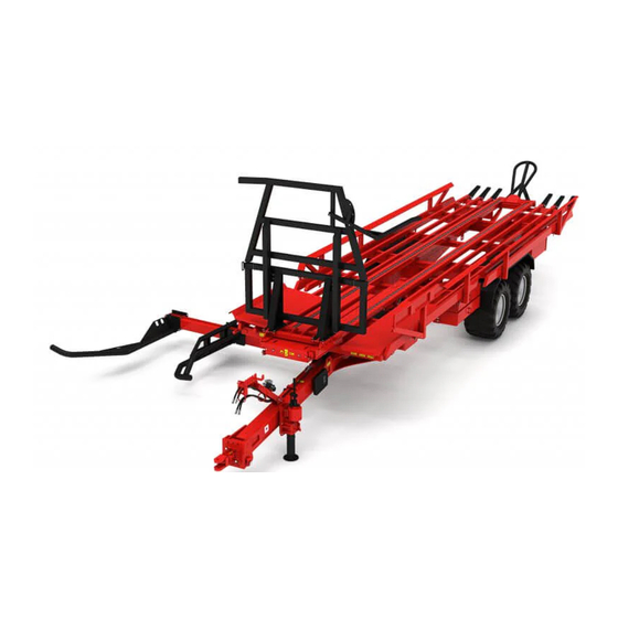
1 Introduction Congratulations! You have just acquired an Anderson self-loading bale carrier, a quality machine designed specifically for handling round bales. 1.1 Overview The following figures show the main components of the RBM1400, RBM2000 and RBM2000S bale carrier models. Figure 1 — Main Components of the Self-Loading Bale Carriers 1.2 Technical specifications... - Page 14 Distance between the grabber and the centre of the bale carrier (F) 2.77 m (109 in.) Total width with arm extended (G) 5.54 m (218 in.) Maximum height when unloading (H) 3.45 m (136 in.) Tare weight 5,800 kg (12,787 lb.) GVWR (gross vehicle weight rating) 19,000 kg (41,888 lb.) Operator's Manual – Self-Loading Bale Carrier Anderson Group...
- Page 15 Minimum tractor hydraulic flow: 38 Lpm (10 gpm) Maximum tractor hydraulic flow: 80 Lpm (21 gpm) Minimum tractor hydraulic pressure: 172 bar (2,500 psi) Maximum tractor hydraulic pressure: 207 bar (3,000 psi) 3 dual-effect hydraulic control systems Anderson Group Self-Loading Bale Carrier – Operator's Manual...
- Page 16 Distance between the grabber and the centre of the bale carrier (F) 2.77 m (109 in.) Total width with arm extended (G) 5.54 m (218 in.) Maximum height when unloading (H) 4.78 m (188 in.) Tare weight 6,100 kg (13,448 lb.) Operator's Manual – Self-Loading Bale Carrier Anderson Group...
-
Page 17: Options
4 dual-effect hydraulic control systems (RBM2000S) 1.3 Options The following table shows the optional parts available for your bale carrier. Table 5 — Optional Parts for the RBM Self-Loading Bale Carriers Option RBM1400 RBM2000 RBM2000S Air brake Anderson Group Self-Loading Bale Carrier – Operator's Manual... -
Page 18: Machine Identification
You must always have this information on hand when ordering replacement parts or requesting assistance from our customer service department. You can record the identification information of your equipment in Figure 4. Operator's Manual – Self-Loading Bale Carrier Anderson Group... -
Page 19: Safety And Maintenance Pictograms
Warning! Check the tightening torque on the lug nuts. Lubricate with grease at the frequency recommended in "Greasing" on page 71. Lubricate with oil at the frequency recom- mended in "Maintenance schedule" on page 69. Anderson Group Self-Loading Bale Carrier – Operator's Manual... - Page 20 Remain at a safe distance. Warning! Before doing any maintenance or repairs, turn off the engine, remove the key, and see "Maintenance" on page 67. Warning! Pressurized hydraulic hoses. See "Maintenance" on page 67. Operator's Manual – Self-Loading Bale Carrier Anderson Group...
- Page 21 Do not open or remove the guard when the engine is running. Warning! Never climb, or allow anyone else to climb, on the tables or on the equip- ment while it is operating. Anderson Group Self-Loading Bale Carrier – Operator's Manual...
- Page 22 Maximum speed of 25 km/h (15 mph). Adjust the forks before beginning a load (see "Adjusting the forks" on page 45). Warning! Before checking and adjusting the chain tension, see "Maintenance" on page 67. Operator's Manual – Self-Loading Bale Carrier Anderson Group...
-
Page 23: Safety Precautions
2 Safety precautions Your Anderson machine was designed to minimize risk to the operator. Nevertheless, it must only be used for its intended purpose. Misuse of the machine may result in injury to the operator. The machine has a hydraulic system and moving mechanical parts. All these components can cause serious or even fatal injury to people and animals. - Page 24 Ensure that the warnings and pictograms remain clean and clearly visible. In the event of damage, ask your manufacturer (or dealer) for new labels. During repairs, ensure that the replacement parts bear the same labels as the original parts. Operator's Manual – Self-Loading Bale Carrier Anderson Group...
-
Page 25: Safety Tips For Transport
Ensure that the underrun protection bar is down toward the ground (safety position) before driving on public roads with the bale carrier. Anderson Group Self-Loading Bale Carrier – Operator's Manual... - Page 26 Completely close the bale guides and the adjustable support for 1.8 m (6 ft.) bales (Details A and D). Insert the loading arm locking pin (Detail B). Close the ball valve for the unloading cylinders (Detail C). Operator's Manual – Self-Loading Bale Carrier Anderson Group...
-
Page 27: Safety Tips For Hitching
Before hitching the equipment, ensure that the tractor lift controls are set so that the tractor cannot move during the process. Once the equipment is hitched, lock the coupling device. Check that the hitch is correctly locked and in good condition before moving. Anderson Group Self-Loading Bale Carrier – Operator's Manual... -
Page 28: Safety Tips For Maintenance And Repairs
For welding operations on the equipment or tractor, disconnect the battery or electrical power supply and protect the lines (especially rubber hoses) to prevent them from being damaged by sparks, which could cause a loss of oil, hydraulic fluid, etc. Operator's Manual – Self-Loading Bale Carrier Anderson Group... - Page 29 Immediately replace any damaged or defective guards or locks. Original guards affixed to the machine must not be removed or modified. The hoses must not come from piping used in another system. Immediately replace any damaged hoses. Anderson Group Self-Loading Bale Carrier – Operator's Manual...
-
Page 30: Waste Recovery
Return used fluids to a collection and reprocessing centre so that they are recycled or disposed of in accordance with legislation. Stockpiling, abandoning or dumping tires is prohibited, as is burning them outdoors. Return them to an approved distributor or collector. Operator's Manual – Self-Loading Bale Carrier Anderson Group... -
Page 31: Getting Started
6. Remove the wheel chocks and disengage the bale carrier handbrake (if applicable). To unhitch the equipment: 1. Position the equipment on a level and stable surface, turn off the tractor engine and relieve the pressure in the hydraulic hoses. Anderson Group Self-Loading Bale Carrier – Operator's Manual... - Page 32 5. Remove the cotter pin from the hitch pin, remove the hitch pin, and remove the safety chain (Figure 6). 6. Uncouple the bale carrier drawbar from the tractor drawbar. Figure 6 — Hitching to the Tractor Figure 7 — Hydraulic Jack Extended (A) and in Transport Position (B) Operator's Manual – Self-Loading Bale Carrier Anderson Group...
-
Page 33: Connecting The Hydraulic And Electrical Systems
The functions will be reversed (RBM1400 and RBM2000S). This could result in equipment failure! Relieve the pressure in the tractor's hydraulic system and ensure that the couplings are clean before connecting them. Dirt will contaminate the tractor's hydraulic oil. Anderson Group Self-Loading Bale Carrier – Operator's Manual... - Page 34 1 green cable tie RBM2000 valve Pressure 2 green cable ties Option for the RBM1400 and selector valve RBM2000S Return for the selector 1 green cable tie Option for the RBM1400 and valve RBM2000S Operator's Manual – Self-Loading Bale Carrier Anderson Group...
-
Page 35: Connecting The Hydraulic Brakes (Option)
The valve pin must be inserted from the bottom to the top (see Figure 9). The W-shaped arm of the pin must be facing toward the front of the bale carrier (tractor side). Anderson Group Self-Loading Bale Carrier – Operator's Manual... - Page 36 2. Ensure that the straight arm of the pin is vertical and is touching the emergency valve. 3. Disconnect the hydraulic hose from the tractor brakes. Operator's Manual – Self-Loading Bale Carrier Anderson Group...
- Page 37 NOTE: If, following an impact, the bale carrier detaches from the tractor and the emergency valve triggers the emergency brakes, it is recommended that you replace the cable with a new one. Anderson Group Self-Loading Bale Carrier – Operator's Manual...
-
Page 39: Adjustments
(Figure 10, B) is greater than 50 mm (2 in.), you will need to adjust the height of the hitch. NOTE: Take the measurements on a level surface when the machine is empty and unhitched. Anderson Group Self-Loading Bale Carrier – Operator's Manual... -
Page 40: Adjusting The Jack Height
The jack height is adjustable. Select the position that is most suitable for the tractor drawbar. To adjust the jack height: 1. Hitch the bale carrier to the tractor. 2. Remove the mounting bolts from the jack. 3. Slide the jack to the desired height. Operator's Manual – Self-Loading Bale Carrier Anderson Group... -
Page 41: Positioning The Adjustable Hose Support
Figure 11 — Hydraulic Jack Extended (A) and in Transport Position (B) 4.3 Positioning the adjustable hose support The adjustable hose support can be placed in different positions. Choose the most suitable position. Figure 12 — Adjustable Hose Support Anderson Group Self-Loading Bale Carrier – Operator's Manual... - Page 42 2. Place the support in the desired position by sliding it to extend or retract it and turning it. 3. Put the attachment bolts back in the adjustable hose support. For bale carriers with a brake system (hydraulic or air), position the adjustable hose support parallel to the ground. Operator's Manual – Self-Loading Bale Carrier Anderson Group...
-
Page 43: Adjusting The Bale Guides And Crossbars
The bale guides and crossbars must be adjusted to the dimensions of the bales being transported. The bale guides must be adjusted so that there is 15 cm (6 in.) of space between the bale guides and bales. Anderson Group Self-Loading Bale Carrier – Operator's Manual... - Page 44 Storage of the crossbars for transport 1.22 m (4 ft.) Note: This position can also be used for transport. 1.37 m (4.5 ft.) 1.52 m (5 ft.) 1.68 m (5.5 ft.) 1.83 m (6 ft.) Operator's Manual – Self-Loading Bale Carrier Anderson Group...
-
Page 45: Adjusting The Forks
6. Put bolt B back in. 7. Remove the bolt in position D and put it back in its original position (A). 8. Tighten the A, B, and C bolts. Figure 15 — Adjusting the Forks Anderson Group Self-Loading Bale Carrier – Operator's Manual... - Page 46 Position of bolt A on the inner Position of bolt A on the outer diameter fork fork 1.22 m (4 ft.) 1.35 m (4.5 ft.) 1.52 m (5 ft.) 1.65 m (5.5 ft.) 1.83 m (6 ft.) Operator's Manual – Self-Loading Bale Carrier Anderson Group...
-
Page 47: Adjusting The Front Stopper (Rbm2000 And Rbm2000S)
Table 10 — Position of the Front Stopper Based on the Diameter of Bales Position Bale diameter 1.2 m (4 ft.) 1.35 to 1.5 m (4.5 to 5 ft.) 1.65 to 1.8 m (5.5 to 6 ft.) Anderson Group Self-Loading Bale Carrier – Operator's Manual... -
Page 48: Adjusting The Pusher Travel Stroke
To adjust the space on the RBM2000, adjust the position of the LS_PO_R sensor that detects the pusher at the front of the bale carrier. Figure 18 — Adjusting the Pusher Travel Stroke on the RBM2000 Operator's Manual – Self-Loading Bale Carrier Anderson Group... - Page 49 For bales 1.5 m (5 ft.) in length, store the two stoppers on the pusher (Figure 19, Detail A). Figure 19 — Adjusting the Pusher Travel Stroke on the RBM1400 and RBM2000S Anderson Group Self-Loading Bale Carrier – Operator's Manual...
-
Page 50: Adjusting The Bale Retaining Support
(see "Adjusting the forks" on page 45). If the fork is not adjusted properly, it could collide with the support. Figure 20 — Adjusting the Bale Retaining Support Operator's Manual – Self-Loading Bale Carrier Anderson Group... - Page 51 Table 12 — Adjusting the Bale Retaining Support Based on Bale Diameter Position Bale diameter Auxiliary support lowered 1.2 to 1.5 m (4 to 5 ft.) Auxiliary support raised 1.6 m (5.5 ft.) Auxiliary support raised and support extended 1.8 m (6 ft.) Anderson Group Self-Loading Bale Carrier – Operator's Manual...
-
Page 52: Using Counterweights
If needed, add ballast weights (e.g. tractor scales) to the support. The maximum capacity of the support is 363 kg (800 lb.). Ensure that you do not exceed the maximum capacity. Ensure that the ballast weights are stable and securely attached. Operator's Manual – Self-Loading Bale Carrier Anderson Group... -
Page 53: Operation
(RBM2000 only) See "Troubleshooting" on page 61 to learn which part is activated by each hydraulic control lever. Figure 22 — RBM2000 Fingertip Joystick Table 13 describes the various Fingertip joystick controls. Anderson Group Self-Loading Bale Carrier – Operator's Manual... -
Page 54: Underrun Protection Bar
Annex XXVI, Requirements on rear protective structures). This bar prevents other vehicles from sliding underneath the bale carrier in the event of a collision. NOTE: The bar is available as an option for bale carriers sold in North America. Figure 23 — Underrun Protection Bar Operator's Manual – Self-Loading Bale Carrier Anderson Group... -
Page 55: Loading Bales
This could damage it or cause an accident. Ensure that the underrun protection bar is down toward the ground in safety position before starting to load bales. Anderson Group Self-Loading Bale Carrier – Operator's Manual... - Page 56 Using the outer fork to align bales allows the operator to drive the tractor further from the bales. Using the inner fork gives the operator a better view of the fork. Operator's Manual – Self-Loading Bale Carrier Anderson Group...
- Page 57 Figure 25 — Aligning Bales in the Loading Grabber 5.3.2 Loading bales To load bales: 1. Position the loading arm so that its forks are on either side of the bale to be loaded and slowly move forward. Anderson Group Self-Loading Bale Carrier – Operator's Manual...
- Page 58 (e.g. 13 bales instead of 14). When the first bales that were loaded reach the very back of the bale carrier, the full load indicator will show that the bale carrier is full (Figure 27). Operator's Manual – Self-Loading Bale Carrier Anderson Group...
-
Page 59: Unloading Bales
(e.g. power lines). Ensure that the tractor has enough space to move forward until all the bales are unloaded. NOTE: Ensure that the handbrake has been disengaged before moving the bale carrier. Anderson Group Self-Loading Bale Carrier – Operator's Manual... - Page 60 NOTE: When the platform is fully lowered, keep pressing the control for a few more seconds so that the underrun protection bar lowers toward the ground, in safety position. Operator's Manual – Self-Loading Bale Carrier Anderson Group...
-
Page 61: Troubleshooting
The hydraulic controls must never be used if the bale carrier can be put in motion. Before using the hydraulic controls, ensure that no one will operate the controls at the same time on the tractor. Anderson Group Self-Loading Bale Carrier – Operator's Manual... - Page 62 Function Description Moves the pusher forward ( ) and backward ( ) Raises ( ) and lowers ( ) the loading arm Extends ( ) and retracts ( ) the loading arm Operator's Manual – Self-Loading Bale Carrier Anderson Group...
-
Page 63: Sensors (Rbm2000)
Detects when the arm is retracted LS_BR_45 Detects when the loading arm is at a 45° angle LS_PO_M Detects when the pusher is in the middle position LS_PO_R Detects when the pusher is in the forward position Anderson Group Self-Loading Bale Carrier – Operator's Manual... - Page 64 Figure 29 — Sensor Locations Operator's Manual – Self-Loading Bale Carrier Anderson Group...
-
Page 65: Common Problems
There is an electrical, connection or sensor Check that the wiring and problem (RBM2000). connections are in good con- dition. Check that the travel limit sensors on the loading arm are in good condition. Anderson Group Self-Loading Bale Carrier – Operator's Manual... - Page 66 The arm is at less than a 45° angle. Raise the arm to 45°. For any other problems, please contact your dealer or our technical service department. Operator's Manual – Self-Loading Bale Carrier Anderson Group...
-
Page 67: Maintenance
A safety stand is provided so that you can safely perform maintenance and repairs underneath the bale carrier platform. The stand is stored on the side of the bale carrier, as shown in Figure 30. Anderson Group Self-Loading Bale Carrier – Operator's Manual... - Page 68 3. Insert the locking pin in the hole and insert the cotterpin to keep it in place. 4. Slowly lower the platform until its weight is resting on the stand. Figure 31 — Setting Up the Safety Stand Ensure that you do not crush the stand. Operator's Manual – Self-Loading Bale Carrier Anderson Group...
-
Page 69: Maintenance Schedule
7.10 (hay, dust, etc.) Check tire pres- Section sure Check that the lug nuts Section are tight Check that the hubcaps Section attached securely Check wheel bear- Section ing play Anderson Group Self-Loading Bale Carrier – Operator's Manual... - Page 70 Adjust brake slack Section Grease the cylinder Section joints Grease the tandem axle Section pivots (4) Grease the drawbar Section pivot (1) Grease the bearings Section Oil the trans- mission Section chains Operator's Manual – Self-Loading Bale Carrier Anderson Group...
-
Page 71: Greasing
Adjust Section pusher trans- mission chain ten- sion 7.2 Greasing Your self-loading bale carrier must be greased using a gun in various places indicated by the label in the following figure: Anderson Group Self-Loading Bale Carrier – Operator's Manual... - Page 72 Figure 32 — Greasing Point Marker NOTE: Anderson Group recommends using synthetic grease. Table 18 — Greasing Frequency Part (number of greasing points) Every 50 hours of use Tandem axle pivots (4) Drawbar pivot (1) All other pivots (7) All cylinder joints (10)
- Page 73 Figure 33 — Platform Greasing Points Anderson Group Self-Loading Bale Carrier – Operator's Manual...
- Page 74 Figure 34 — Greasing Points at the Front of the Bale Carrier Operator's Manual – Self-Loading Bale Carrier Anderson Group...
- Page 75 Figure 35 — Pusher Greasing Points Anderson Group Self-Loading Bale Carrier – Operator's Manual...
- Page 76 Figure 36 — Loading Arm Greasing Points (RBM2000 and RBM2000S) Figure 37 — Greasing Points at the Rear of the Bale Carrier Operator's Manual – Self-Loading Bale Carrier Anderson Group...
-
Page 77: Adjusting The Tension Of The Pusher Chains
(Figure 38), and the rollers on each chain interlock with the same teeth on the two sprockets (Figure 39). Figure 38 — Synchronizing the Chains Anderson Group Self-Loading Bale Carrier – Operator's Manual... - Page 78 Stop tightening the nut once the washer touches the stopper; if not, the chain will be under too much tension, which can cause premature wear and tear on the chain and sprocket. Figure 40 — Adjusting the Tensioner Nuts Operator's Manual – Self-Loading Bale Carrier Anderson Group...
-
Page 79: Adjusting The Pusher Transmission Chain Tension
Apply the same tension to the two pusher chains. 7.4 Adjusting the pusher transmission chain tension After the first 50 hours of use and every 100 hours thereafter, you will need to adjust the pusher transmission chain tension. Anderson Group Self-Loading Bale Carrier – Operator's Manual... -
Page 80: Tire Pressure
3. Tighten the four (4) bolts underneath the transmission (A, Figure 42). Figure 42 — Adjusting the Pusher Transmission Chain Tension 7.5 Tire pressure Check the tire pressure before each use. The pressure should be 2.8 bar (40 psi). Operator's Manual – Self-Loading Bale Carrier Anderson Group... -
Page 81: Maintaining And Adjusting The Axles
450 mm (18 60 kg (132 lb.-ft.) in.) lb.) 7.6.2 Tightening the lug nuts Using a torque wrench, the nuts must be gradually tightened one after another in the order shown in Figure 44. Anderson Group Self-Loading Bale Carrier – Operator's Manual... - Page 82 For pop-on hubcaps, visually check that they are all the way on. For hubcaps with screws, replace the gasket each time the hubcap is removed and tighten the screws every 6 months. Operator's Manual – Self-Loading Bale Carrier Anderson Group...
- Page 83 4. Tighten the castle nut (right-hand threads) to take up all the internal play. The tapered roller bearings will be firmly in contact with the hub shoulders, support ring, spindle, and castle nut, and the rotation of the hub or wheel will drag slightly. Anderson Group Self-Loading Bale Carrier – Operator's Manual...
- Page 84 10. Put the wheel back on (see "Assembling and attaching the wheels" on page 81 and "Tightening the lug nuts" on page 81). Once the wheel is back on, turn it slightly. The wheel should come to rest with a slight rocking movement. Figure 45 — Wheel Bearing Operator's Manual – Self-Loading Bale Carrier Anderson Group...
- Page 85 To remove the wheel bearings for cleaning and inspection (Figure 45 and Figure 46): 1. Loosen the lug nuts. 2. Lift the axle until the wheel is no longer resting on the ground. Anderson Group Self-Loading Bale Carrier – Operator's Manual...
- Page 86 7. Apply a generous coat of grease to the cage and rollers of the small bearing, and put the small bearing on the spindle. Operator's Manual – Self-Loading Bale Carrier Anderson Group...
- Page 87 NOTE: Unpack the bearings at the last minute and be careful to avoid mixing up their parts. To replace the wheel bearings: Anderson Group Self-Loading Bale Carrier – Operator's Manual...
- Page 88 (in the correct direction). Make sure it is centred and remains in place throughout the process of putting the outer race back in. 4. Perform a final check. Figure 48 — Outer Race Operator's Manual – Self-Loading Bale Carrier Anderson Group...
-
Page 89: Maintaining And Adjusting The Brakes (Option)
Carry out the same checks as when getting started and after doing the first loaded run (see "Checking the brakes when getting started" on page 89). Anderson Group Self-Loading Bale Carrier – Operator's Manual... - Page 90 (Figure 51). To take up the slack, turn the screw so that the bearing turns in the same direction. To prevent the brake from overheating, make sure that the wheel turns freely when the brake is not engaged. Operator's Manual – Self-Loading Bale Carrier Anderson Group...
- Page 91 The condition and tightness of the anchor pins (depending on the model). For shoes with rollers, check that they rotate properly and lightly oil the roller pin before assembling. Replace any components that are defective or worn. Anderson Group Self-Loading Bale Carrier – Operator's Manual...
-
Page 92: Maintaining The High-Pressure Filter (Rbm2000)
If it is red, it must be replaced. NOTE: If your filter does not have an indicator, remove the filter in order to inspect the cartridge and replace it if needed. Operator's Manual – Self-Loading Bale Carrier Anderson Group... -
Page 93: Maintaining The Hydraulic Jack
At the end of each day using the bale carrier, ensure that the hydraulic valve and platform rollers are clean. Any debris (hay, dust, and mud) that has accumulated on or in these components can prevent them from working properly. Anderson Group Self-Loading Bale Carrier – Operator's Manual... -
Page 94: Storage
If you do not plan on using the bale carrier for a long time, store it on a flat surface. For your safety, chock the wheels to prevent the bale carrier from moving. NOTE: Anderson Group strongly recommends cleaning and performing general maintenance on the machine before storing it for long periods. NOTE:... - Page 95 ANDERSON GROUP 5125 De la Plaisance St. Chesterville, QC G0P 1J0 CANADA Email: service@grpanderson.com Phone: 1-819-382-2952 Fax: 1-819-382-2218 www.grpanderson.com...
Need help?
Do you have a question about the RBM 1400 and is the answer not in the manual?
Questions and answers
the bale pusher will not retract
The Anderson RBM 1400 bale pusher may not retract due to several possible reasons:
1. Hydraulic Controls Issue – The hydraulic controls must be used correctly, and no one should be operating the tractor controls simultaneously.
2. Sensor Misalignment – If the LS_PO_R sensor is not correctly positioned, it may not detect the pusher's front position, preventing proper retraction.
3. Obstruction – There may be an obstruction in the pusher's path, preventing movement.
4. Improper Joystick Operation – The Fingertip joystick must be pressed three times lightly for automatic retraction.
5. Mechanical Failure – A mechanical issue with the pusher system, such as a stuck component, may need inspection.
Check these factors to diagnose and resolve the issue.
This answer is automatically generated