Table of Contents
Advertisement
Advertisement
Chapters
Table of Contents

Subscribe to Our Youtube Channel
Related Manuals for Anderson TRB-2000


Summary of Contents for Anderson TRB-2000
- Page 1 # 404626-4 Round Bale Trailer TRB-2000 Operator’s Manual 2015...
- Page 3 In case of sale or transfer, give this manual to the new owner. The illustrations in this manual are presented for your reference according to the latest information available at the moment of printing. ANDERSON GROUP reserves the right to modify its machines without advance notice.
-
Page 4: Table Of Contents
Table of Contents 1 Anderson limited warranty ....................4 Purpose of Warranty: ...................... 5 Warranty Exemptions: ..................... 5 No Dealer Warranty: ....................... 5 Anderson’s Responsibilities: ..................... 6 2 Safety ..........................7 Safe Operators ........................ 7 Danger Zone ........................7 Secure Attachment to the Tractor ..................7 Dangerous Situations ...................... - Page 5 - Product model and serial number; - Purchase date and invoice number; - Dealer name, address, and telephone number and salesperson name; - Precise and detailed description of your problem. ANDERSON GROUP Address: 5125 de la Plaisance Chesterville (Québec) CANADA G0P 1J0 Email Service: service@grpanderson.com...
-
Page 6: Anderson Limited Warranty
In no event will Anderson be liable for any incidental or consequential damages or injuries, including but not limited to loss of profits, rental of substitute equipment, or other commercial or personal loss or damages arising as a result of a fundamental breach or breach of a fundamental term. -
Page 7: Purpose Of Warranty
The fundamental responsibility of warranty is to correct defects in material and workmanship of the products sold by Group Anderson Inc. (hereafter called ‘’Anderson’’). This outline is intended to assist you in awareness of Anderson’s Warranty Policies and to assure that you obtain the best service possible for your Anderson machine. ... -
Page 8: Anderson's Responsibilities
Anderson’s Responsibilities: In the event that parts must be shipped from Anderson, freight will be paid by Anderson and will be shipped by the most economical means to arrive in the shortest possible time. Air, Next Day Air, Priority and other special shipment methods requested by the Dealer will be at the Customer’s expense. -
Page 9: Safety
2 Safety Your ANDERSON self-loading trailer was designed to reduce to a minimum the risks to the operator. However, it must be used only for the work it was designed for. Additionally, since it includes a powerful hydraulic system and moving metal parts and all these elements can cause serious injury to humans or animals, it is strongly recommended to read and to closely adhere to the following guidelines. -
Page 10: Hydraulic Oil
Hydraulic Oil Any leak of pressurized oil can cause serious injuries. Do not use your hands to locate a leak, but rather an object such as a piece of cardboard. Stop the tractor and release the pressure before disconnecting or reconnecting the lines. Any hydraulic fluid that makes contact on or underneath the skin must be removed within hours by a doctor familiar with this type of injury. -
Page 11: General Characteristics And Specifications
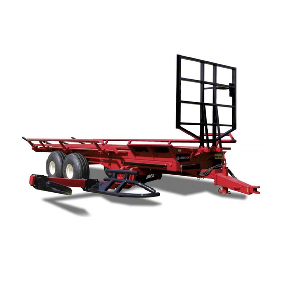
3 General Characteristics and Specifications Congratulations! You are now the owner of an ANDERSON TRB self-loading round bale trailer, a high-quality mac hine des igned f or ha ndling and transporting d ry or wet b ales of hay. Thi s agricultural m achine is car efully m anufactured by o ur c ompany t o gi ve yo u m any y ears o f reliable performance. -
Page 12: Standard Components
0.4 m (15 in.) of ground clearance and uniform, minimal ground pressure. The loading capacity is 14,000 kg (30,000 lbs). Detailed diagrams of the different parts of the trailer can be found in the PARTS BOOK. Standard Components TRB-2000 Loading arm Pusher Adjustable ring hitch... -
Page 13: Adjustment Procedures
4 Adjustment Procedures Installing the trailer on the tractor When you first use the TRB trailer with a tractor, it is important to make sure that the trailer is completely level. The height of the ring hitch is adjustable so that the trailer can adapt to different types of tractors. -
Page 14: Adjusting The Bale Guides
Figure 4.2 Loading arm adjustment based on bale length The loading arm is equipped with a security device that blocks the use of the pusher and the lifting of the unloading platform when it is in raised position. To perform the actions of bale pushing and unloading, the arm must be around the middle of its range. -
Page 15: Pusher Adjustment
Bales 1.5 m (5 ft) in diameter Bales 1.8 m (6 ft) in diameter* Figure 4.3 Bale guide adjustment * The configuration to transport bales 1.8 m (6 ft ) in diameter requires the optional bale guide extensions. Pusher Adjustment The pusher of the TRB trailer is equipped with a limit stop that makes it possible to transport bales 1.2 m (4 ft) or 1.5 m (5 ft) in length (see Figure 4.4). -
Page 16: Operation
5 Operation Commands The following figure represents the control lever and the functions associated with each button. Figure 5.1 Control lever Telescopic Pusher Loading arm... -
Page 17: Start-Up
Start-Up Here are the steps to start using your TRB trailer. 1. Attach the trailer to the tractor. 2. Lift up the jack 3. Connect the 6 hydraulic hoses to the tractor (or the 4 hydraulic hoses and the selection valve to the tractor’s 12 V current). Note that the utmost cleanliness is recommended whenever you connect these parts to avoid oil contamination problems. - Page 18 Figure 5.2 Bale position in loading arm When the loading arm is resting on the aligned bale, raise the loading arm. The first bale will be automatically placed on the side of the trailer platform opposite the loading arm.
- Page 19 When you load the second bale, it will be placed on the platform on the same side as the loading arm. To load the bale on the second row, extend the loading arm when it is raised to the middle of his stroke.
-
Page 20: Unloading The Trailer
Full load Space available Figure 5.4 Full load indicator Unloading the Trailer To unload the TRB trailer, it is very important to choose level ground and to make sure that there are no obstacles, such as an electrical transmission line. Bring the trailer to a stop at the place where you want to unload the bales. -
Page 21: Maintenance
6 Maintenance Maintenance Before performing any maintenance operations on your machine, ensure that you are following the security precautions laid out in the safe maintenance and repair section: stop the engine (of the tractor or the unit), release hydraulic pressure, install the safety stands, etc. Safety Stands Safety stands are provided so that you can safely perform maintenance and make repairs underneath the trailer platform. - Page 22 Greasing Frequency Frequency Greasing (number of grease cups) Draw bar (1) Pusher cylinder joints (2) Loading arm joint (2) Every 10 hours of Arm cylinder joints (2) Tandem axle pivots (4) Platform cylinder joints (4) Platform pivots (2) Draw bar (1) Pusher cylinder joints (2)
- Page 23 Loading arm joint (2) Arm cylinder joints (2) Extension arm cylinder (2) Tandem axle pivots (4)
-
Page 24: Other Lubrication Points
Platform cylinder joints Platform pivots Other Lubrication Points The lubrication of the axles needs to be checked every year. Cleaning and Other Maintenance Pay special attention to the cleanliness of the rail system of the pusher and to the loading arm joint. -
Page 25: Troubleshooting: Problems And Solutions
7 Troubleshooting: Problems and Solutions Before calling a technician, examine your trailer and consult the table below to find a solution. Attempt to isolate the problem to find out if it is a hydraulic or electrical problem by using the manual functions on the hydraulic valve. - Page 26 Make sure that limit switches on the loading arm are in good condition For other problems not provided in this manual, contact the dealer authorized in your area or our service department Warning! ANDERSON GROUP Address: 5125 de la Plaisance Chesterville (Québec) CANADA G0P 1J0 Email Service: service@grpanderson.com...
-
Page 27: Quick Start-Up
8 Quick Start-Up Installation on the Tractor Attach the trailer to the tractor. Lift up the jack. Connect the 6 hydraulic hoses to the tractor (OR the 4 hydraulic hoses and the selection valve to the 12 V current of the tractor). Note that the utmost cleanliness is recommended whenever you connect these parts to avoid oil contamination problems. - Page 29 Parts manual TRB-2000 Round Bale Trailer ALWAYS KEEP THIS MANUAL WITH THE TRAILER...
- Page 31 16 – Wheel chock (option) 17 – Handbrake (option) For any parts order, please use the parts manual to find the item(s) you need and contact your dealer to order it. ANDERSON GROUP 5125 Plaisance street Chesterville (Québec) CANADA G0P 1J0...
-
Page 32: Hydraulic Diagram
2 GREEN TIE-WRAP 59-11-B 1 X 9315-10-8 1 X 3524-08-08 1/2 NPTM 3 X 3759-8 QUICK 4 X 5205-8-8 COUPLING CHECK VALVE HSP1000-4-65 59-09 1 x 5129-08 Anderson Group, 5125 de la Plaisance Chesterville (Québec) G0P 1J0 Email : service@grpanderson.com... - Page 33 59-18 234571-1 59-07 234581-1 59-19 234573-1 59-09 234582-1 59-20 234617 59-10 234583-1 59-21 234574-1 59-11-A 234584-1 59-22 234574-2 59-11-B 234585-1 59-23 234575-1 59-12 234576-1 59-13 234618-2 59-14-A Anderson Group, 5125 de la Plaisance Chesterville (Québec) G0P 1J0 Email : service@grpanderson.com...
-
Page 36: Electrical Diagram
315199 CABLE JOYSTICK TO CONTROLE TRB-2000 LOADING TÉLES- PUSHER INVERSER COMPUTER KIT (TRB-2000) 315200 COPIC 315201 POWER CABLE TRB-2000 315202 MAIN CABLE FOR COMPUTER TRB-2000 SELECTOR VALVES Anderson Group, 5125 de la Plaisance Chesterville (Québec) G0P 1J0 Email : service@grpanderson.com... -
Page 37: Loading Arm / Loading Arm Cylinder
3 - LOADING ARM Groupe Anderson, 5125 de la Plaisance Chesterville (Québec) G0P 1J0 Email : service@grpanderson.com... - Page 38 FLAT HEAD SOCKET CAP SCREW ALLEN 234622 SHIME 501907 THREADED INSERT 485139 TEFLON 500173 BOLT 501035-1 NYLON NUT 500268-1 BOLT 450716M HYDRAULIC FITTING 451171 6 M.JIC- 6M.ORB Groupe Anderson, 5125 de la Plaisance Chesterville (Québec) G0P 1J0 Email : service@grpanderson.com...
-
Page 39: Tandem
FLAT WASHER 1 1/4 Z 502013 COTTER PIN 1/4 X 3 320017 481004 501902 HEX WHEEL NUT 5/8-18 234004 RIGHT TANDEM 234016 TANDEM AXLE 500212 BOLT 218001 FLAT WASHER Anderson Group, 5125 de la Plaisance Chesterville (Québec) G0P 1J0 Email : service@grpanderson.com... - Page 40 COTTER PIN ¼ X 3 303510 SEAL 500040 BOLT 5/16 X 1/2 NC GR5 303492 BEARING CUP 28921* 303491 BEARING 28995* 481020 322299 GREASE FITTING TANDEM AXLE 481006 WHEEL STUD Anderson Group, 5125 de la Plaisance Chesterville (Québec) G0P 1J0 Email : service@grpanderson.com...
-
Page 42: Frame / Unload Cylinder
5 - FRAME / UNLOADING CYLINDER DETAIL B DETAIL C DETAIL D DETAIL G DETAIL E DETAIL H Anderson Group, 5125 de la Plaisance Chesterville (Québec) G0P 1J0 Email : service@grpanderson.com... - Page 43 500059 HEX BOLT GR5 5/16-18 X 3 1/4 320023-1 LOCK PIN 3IN 451356 HYDRAULIC FITTING 465576 PRESSURE SWITCH 465929 HYDRAULIC VALVE 450505 HYDRAULIC FITTING 450504 HYDRAULIC FITTING Anderson Group, 5125 de la Plaisance Chesterville (Québec) G0P 1J0 Email : service@grpanderson.com...
-
Page 44: Tongue
HEX BOLT GR5 1/2-13 X 1 1/2 500324-1 HEX BOLT GR8 1-14 X 2 1/2 Z 234106 LOCK WASHER 234193 DRAW BAR 234109-2 WASHER 234192-1 TRAILER TONGUE CONE Groupe Anderson, 5125 de la Plaisance Chesterville (Québec) G0P 1J0 Email : service@grpanderson.com... - Page 45 NYLON NUT 234028 INNER HOUSING 234199 LINK 234201 234200 INDICATOR ROCKER 500084 BOLT 501032-1 NYLON NUT 234114-1 REAR SUPPORT TUBE WITH INDICATOR 234031-1 REAR SUPPORT 501037 NYLON NUT Anderson Group, 5125 de la Plaisance Chesterville (Québec) G0P 1J0 Email : service@grpanderson.com...
- Page 46 8 - PLATEFORM / PUSHER DETAIL B DETAIL A DETAIL D DETAIL C Anderson Group, 5125 de la Plaisance Chesterville (Québec) G0P 1J0 Email : service@grpanderson.com...
-
Page 47: Platform
500191 BOLT 501036 NYLON NUT 322108 SHAFT COLLARS 320010 HITCH PIN 3/16 320091 500086 BOLT 500103 HEX BOLT GR5 3/8-16 X 3 3/4 481012 PLUG 481007 PLUG Anderson Group, 5125 de la Plaisance Chesterville (Québec) G0P 1J0 Email : service@grpanderson.com... -
Page 48: Feet Bale Kit (Option)
72'' INDICATOR REAR SUPPORT HOUSING 234200 INDICATOR ROCKER 234199 LINK 234205 234189 72'' INNER HOUSING 501032-1 NYLON NUT 500086 BOLT 234187-1 REAR SUPPORT 72 IN. 501037 NYLON NUT Anderson Group, 5125 de la Plaisance Chesterville (Québec) G0P 1J0 Email : service@grpanderson.com9-... - Page 50 10 - HYDRAULIC BRAKE DETAIL B DETAIL C DETAIL A Anderson Group, 5125 de la Plaisance Chesterville (Québec) G0P 1J0 Email : service@grpanderson.com...
- Page 51 HYDRAULIC FITTING 470108 ACCUMULATOR 234118 ACCUMULATOR FIXING BRACKET 500113 BOLT 501032 NYLON NUT 234117 EMERGENCY WIRE 500182 BOLT 501034 NYLON NUT 451172 HYDRAULIC FITTING 467324 HYDRAULIC CYLINDER Anderson Group, 5125 de la Plaisance Chesterville (Québec) G0P 1J0 Email : service@grpanderson.com...
- Page 52 HOSE #2 HOSE #4 HOSE #6 (4X) HOSE #5 FIX ON THE BRAKE LEVER : TRB1000-TRB1400-TRB2000 = 175 MM (4) PARKING BRAKE (WIRE) : 200 MM (5) Anderson Group, 5125 de la Plaisance Chesterville (Québec) G0P 1J0 Email : service@grpanderson.com...
- Page 53 ADAPTEUR 5315-6-8 465069 BREAKAWAY VALVE 451172 ADAPTEUR 5315-6-8 470129 ACCUMULATEUR ACS 1 450862 ADAPTEUR 5705-6 467332 CYL_SRBR25SL TRB100 467345 CYL_SRBR30SL TRB1000-1400-2000 467324 CYL_SRBR25 TRB100 467344 TRB1000-1400-2000 CYL_SRBR30 Anderson Group, 5125 de la Plaisance Chesterville (Québec) G0P 1J0 Email : service@grpanderson.com...
- Page 54 10 - AIR BRAKE DETAIL B DETAIL A DETAIL D DETAIL C Anderson Group, 5125 de la Plaisance Chesterville (Québec) G0P 1J0 Email : service@grpanderson.com...
- Page 55 AIR TANK SUPPORT 325163 VALVE MANUEL DE CHARGEMENT 234802 VALVE SUPPORT 500042 HEX BOLT GR5 5/16-18 X 3/4 507006 HEX SELF-THREADING SCREW 1/4-14 X 1PO Z 452490 HYDRAULIC FITTING Anderson Group, 5125 de la Plaisance Chesterville (Québec) G0P 1J0 Email : service@grpanderson.com...
- Page 58 ITEM DESCRIPTION NOTE QTÉ PIÈCE BRAKE SUPPORT 359 BRAKE ASSEMBLY 350*090 359 CAM SHAFT WASHER RETAINING RING BREAK LEVER SUPPORT DE L'ABRE À CAMES RETAINING RING DRUM Anderson Group, 5125 de la Plaisance Chesterville (Québec) G0P 1J0 Email : service@grpanderson.com...
- Page 59 QTÉ PIÈCE BEARING 32213 BEARING 32216 OIL SEAL NILOS 32213 NILOS 32216 SPRING PIN CAP WHIT GASKET SCREW HUB 8 TROUS(61L8TD002) HUB 10 TROUS(61L1TD002) HUB 10 TROUS(61LRTD001) Anderson Group, 5125 de la Plaisance Chesterville (Québec) G0P 1J0 Email : service@grpanderson.com...
- Page 60 PARTS LIST ITEM PART DESCRIPTION NOTE 234206-1 BALE GUIDE EXTENTION 234207-1 REAR BALE GUIDE EXTENTION 500175 HEX BOLT GR5 1/2-13 X 1 1/4 DETAIL A DETAIL B Anderson Group, 5125 de la Plaisance Chesterville (Québec) G0P 1J0 Email : service@grpanderson.com...
-
Page 61: Tire (Option)
PIÈCE 234771 STOPPER 500513 BOULON À CARROSSERIE GR5 1/2-13 X 5 1/2 Z 501034 ÉCROU NYLON IND HEX GR5 1/2-13 Z Must be installed with tires 700 Anderson Group, 5125 de la Plaisance Chesterville (Québec) G0P 1J0 Email : service@grpanderson.com... -
Page 62: Tongue /Hand /Security (Option)
DRAW BAR 501078 HEX NYLON LOCKNUT GR5 1 1/4-7 Z 234233 BUSHING 234234 WASHER 302021 SAFETY CHAIN 500352 BOLT 234024-1 TONGUE 213078 TWING EYE COUPLING 506054 BOLT Groupe Anderson, 5125 de la Plaisance Chesterville (Québec) G0P 1J0 Email : service@grpanderson.com... - Page 63 13 - TONGUE EXTENSION (OPTION) PARTS LIST ITEM PART DESCRIPTION NOTE 234735 DRAWBAR EXTENSION 501036-1 NYLON NUT 500213-2 BOLT 500324-1 BOLT 501058 NYLON NUT Anderson Group, 5125 de la Plaisance Chesterville (Québec) G0P 1J0 Email : service@grpanderson.com...
-
Page 64: Big Fork (Option)
14 - BIG FORK PARTS LIST ITEM PART DESCRIPTION NOTE 234110 BIG FORK WITH WIDE PLATE Anderson Group, 5125 de la Plaisance Chesterville (Québec) G0P 1J0 Email : service@grpanderson.com... - Page 65 BOLT 501035 NYLON NUT 234097-2 REMOVABLE BALE GUIDE SUPPORT 234096-2 REMOVABLE BALE GUIDE SUPPORT 234128 LIGHT BOX 234127 LIGHT SUPPORT 500082 BOLT 234137 LICENSE PLATE DETAIL A Anderson Group, 5125 de la Plaisance Chesterville (Québec) G0P 1J0 Email : service@grpanderson.com...
-
Page 66: Wheel Chock (Option)
NYLON NUT 501032 NYLON NUT 500084 BOLT 500004 BOLT 325162 RATCHET HAND BRAKE 325161 WHEEL CHOCK SUPPORT 325160 WHEEL CHOCK 234235 WHEEL CHOCK SUPPORT PLATE DETAIL A Anderson Group, 5125 de la Plaisance Chesterville (Québec) G0P 1J0 Email : service@grpanderson.com... - Page 67 234669 PULLEY TENSIONER 1 234670 PULLEY TENSIONER 1 325165 PULLEY 304047 SPRING 500180 HEX BOLT GR5 1/2-13 X 2 500090 HEX BOLT GR5 3/8-16 X 1 3/4 Anderson Group, 5125 de la Plaisance Chesterville (Québec) G0P 1J0 Email : service@grpanderson.com...
Need help?
Do you have a question about the TRB-2000 and is the answer not in the manual?
Questions and answers