Advertisement
Quick Links
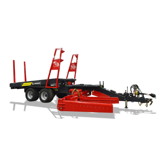
DIAGNOSTIC GUIDE FOR STACKPRO
When navigating the pages you will see buttons that send you to the
corresponding procedures / sections of the troubleshooting table. You can also
use the shortcut from the table of contents (procedures) to obtain a specific
procedure. At any time you may click on the Anderson logo at the top of any
page to return to this page.
1
Advertisement

Related Manuals for Anderson STACKPRO Series


Summary of Contents for Anderson STACKPRO Series
- Page 1 / sections of the troubleshooting table. You can also use the shortcut from the table of contents (procedures) to obtain a specific procedure. At any time you may click on the Anderson logo at the top of any page to return to this page.
- Page 2 Table of contents 1. List of all sensors, functionnalities and location # 001 2. Search by « error code » what is my problem # 006 3. Search by « fault error » what is the problem # 011 4. How to test a sensor in order to know if it still work # 007 5.
- Page 3 Bale carrier Diagnostic procedure Model(s) : Stackpro STACKPRO 5400 STACKPRO 7200 My stacked Cannot get the bale are falling Stackpro down started to work Click here to Click here to continue continue Problem with Problem with rear squizzer of loading arm the dumping table Search by “fault...
- Page 4 Bale carrier Diagnostic procedure Model(s) : Stackpro Cannot get the Stackpro started to work The Stackpro move The Danfoss touchscreen The Stackpro dont when i engage the dont want to turn ON. work when i engage lever valve from the manually the lever side, but cannot get it Click here to continue...
- Page 5 Bale carrier Diagnostic procedure Model(s) : Stackpro The Stackpro dont work when i engage manually the lever valve from the side Ensure your Danfoss Controller is powered on Make sure your Danfoss The Danfoss touchscreen Controller is « connected » dont want to turn ON.
- Page 6 Bale carrier Diagnostic procedure Model(s) : Stackpro The Stackpro move when i engage the lever valve from the side, but cannot get it move through the Danfoss Controller Ensure your Danfoss Controller is powered on Make sure your Danfoss The Danfoss touchscreen Controller is «...
- Page 7 Bale carrier Diagnostic procedure Model(s) : Stackpro The Danfoss touchscreen display dont want to turn ON The fuse is burned. I putted a new one and it burned out Inspect the fuse located next to the instantly when i turn the «...
- Page 8 Bale carrier Diagnostic procedure Model(s) : Stackpro From the Danfoss Controller screen, I engage the « manual mode » function, but i’m still unable to move any function from the controller, or from the lever of the valve Near the main valve, there is a «...
- Page 9 Bale carrier Diagnostic procedure Model(s) : Stackpro From the Danfoss Controller screen, I engage the « automatic loading » mode but the screen dont let me do it. Verify that the loading arm as been fully extended out to the right side, and you dont see the « LS Transport » message on the main screen of the controller The arm is fully The arm is fully extended...
- Page 10 Bale carrier Diagnostic procedure Model(s) : Stackpro Problem with loading arm The bale are The loading slipping off the arm don’t want loading arm to move down, clamp when even when loading running the lever directly Click here to continue Click here to continue The bale are...
- Page 11 Bale carrier Diagnostic procedure Model(s) : Stackpro The bale are slipping off the loading arm clamp when loading Make sure the loading arm clamp has been adjusted accordingly to the dimension of your bale Increase the pressure applied to the bale before lifting it up.
- Page 12 Bale carrier Diagnostic procedure Model(s) : Stackpro The bale are not centered on the “loading table” When release by the When release by the loading arm clamp, loading arm clamp, the bale sit on the the bale sit on the loading table off- loading table centered, even...
- Page 13 Bale carrier Diagnostic procedure Model(s) : Stackpro The bale hit the loading table before the arm is horizontally above the loading table You are picking up bale with a loading arm that is setted to low to the ground vs the bale dimension you are trying to picked up.
- Page 14 Bale carrier Diagnostic procedure Model(s) : Stackpro The bale hit the loading arm but it wont pick it up automatically. Inspect the sensor Make sure the LS_BA_PI behind the “automatic loading” « triggering plate » of mode is engaged the loading arm and insure that it work normally Click Here...
- Page 15 Bale carrier Diagnostic procedure Model(s) : Stackpro The loading arm don’t want to move down, even when running the lever directly All others hydraulics There is no hydraulic function work, function working. except the loading Click here Inspect the loading Inspect the loading arm safety valve and arm safety valve coil...
- Page 16 Bale carrier Diagnostic procedure Model(s) : Stackpro Problem with loading table The loading The loading The loading table will raise table do not table will raise to 30 deg, raise high up to 30 deg, extend toward enough in order but stop there the front of the to secure the...
- Page 17 Bale carrier Diagnostic procedure Model(s) : Stackpro The loading table will raise up to 30 deg, but stop there and nothing happen Validate if the “lower Inspect the “30 deg” position sensor” of sensor LS_SL_M and the loading table insure it is LS_SL_B is also positioned engage when the...
- Page 18 Bale carrier Diagnostic procedure Model(s) : Stackpro The loading table will raise to 30 deg, extend toward the front of the Stackpro and stop there Inspect the plastic chain which travel Inspect the “magnet sensor” above the magnet sensor, and insure LS_ED_M is powered, well positioned there is 2 magnet in the chain link, and work accordingly.
- Page 19 Bale carrier Diagnostic procedure Model(s) : Stackpro The loading table do not raise high enough in order to secure the bale between the side gate Locate the sensor LS_SL_H. Raise the loading table at 90 degree, and then position the sensor correctly so the table will stop at that position next time...
- Page 20 Bale carrier Diagnostic procedure Model(s) : Stackpro Problem with bale pusher of the loading table The bale are not push The bale are push with far enough to allow an excessive speed next bale to be loaded toward toward the front The pusher take more than 3 second to push the bale forward and...
- Page 21 Bale carrier Diagnostic procedure Model(s) : Stackpro Problem with Rolling Fork Stackpro7200 Stackpro5400 The rolling fork are When retracting the not moving loading fork backward enough so underneath the stack the bales on the before unloading, I rear-end of the got a sensor error platform are not LS_CH...
- Page 22 Bale carrier Diagnostic procedure Model(s) : Stackpro Problem with unloading platform The dumping table, in The telescopic The dumping table is “unloading mode” “digging” into the cylinder is should stop at 45 ground during the misaligned with the degree so it let the unloading phase.
- Page 23 Bale carrier Diagnostic procedure Model(s) : Stackpro Problem with rear squizzer of the dumping table (Stackpro7200 1 generation) Bale twine are Bale are getting cutted slipping from by the rear the rear squizzer when squizzer unloading The 90 degree The hydraulic sensor pressure is not LS_DP_M of the...
- Page 24 Bale carrier Diagnostic procedure Model(s) : Stackpro Problem with the rear-end pusher when unloading The rear-end pusher retract, but I have the error LS_PD_R. Inspect if the sensor work properly Click here...
- Page 25 CLICK BELOW Functions Detects bales in the loading arm grabber. Initiate the loading sequence LS_BA_PI Detects if the bales has been dropped on the loading table LS_BA_SL Detects when the unloading platform is at it’s lowest position. LS_DP_B Detects when the rolling fork are pushed all the way back to the front LS_CH Detects the position of the unloading platform when reaching 45 degree in order to LS_DP_M...
- Page 26 List of all sensor and their location STACKPRO7200 LS_SL_B 2019 model and before 2020 model and after STACKPRO5400 LS_SL_B 2019 model and before LS_SL_B 2020 model and AFTER...
- Page 27 List of all sensor and their location...
- Page 28 List of all sensor and their location LS_BR_E LS_BR_R...
- Page 29 List of all sensor and their location...
- Page 30 List of all sensor and their location LS_CH...
- Page 31 Procedure to install chain link with magnet on Stackpro 7200 # 002 •First, raise the loading table, then raise dumper and place a safety tube of approximately 30cm length to ensure that dumper is safe. Finally, completely extend the dumper extension.
- Page 32 Procedure to install chain link with magnet on Stackpro 7200 # 002 •With a small flat screw driver, remove the #12 and the #16 plastic link of the chain.
- Page 33 Procedure to install chain link with magnet on Stackpro 7200 # 002 •Insert a slim magnet in the middle of the 2 links •Install the 2 new plastic link with the magnet.
- Page 34 Procedure to install chain link with magnet on Stackpro 7200 # 002 •Test the sensor. Turn ON the control box and press the “Setting” button.. Select “Diagnostic” Look to the status of the LS_ED_M sensor. If the sensor is aligned with the magnet, the status should be ON (green), otherwise, it should be OFF (red).
- Page 35 Protocol to inspect bad wired blowing up the fuses # 003 When inserting a new fuses, if it burned immediatly, it is sign that you have a cutted wired that might have been damaged because it became loose, or a debris cutted it or the wire got cutted by some movement of the Stackpro.
- Page 36 Protocol to inspect bad wired blowing up the fuses # 003 There is the following sensor that could cause the fuse to burn if bad connection. LS_BR_R (LOADING ARM RETRACTED POSITION) (STACKPRO7200 1 generation only) LS_BR_E (LOADING ARM EXTENDED POSITION) (STACKPRO7200 1 generation only)
- Page 37 Protocol to inspect bad wired blowing up the fuses # 003 There is the following sensor that could cause the fuse to burn if bad connection. LS_PO_R (LOADING HANDLE RETRACTED POSITION) LS_BA_PI (BALE DETECTION IN THE GRABBER) LS_SL_H (LIFTING SYSTEM IN LIFTED POSITION)
- Page 38 Protocol to inspect bad wired blowing up the fuses # 003 There is the following sensor that could cause the fuse to burn if bad connection. LS_SL_M (LIFTING SYSTEM IN MIDWAY POSITION) LS_BA_SL(BALE DETECTION ON LIFTING SYSTEM) LS_CH (ROLLING FORK IN FORWARD POSITION)
- Page 39 Protocol to inspect bad wired blowing up the fuses # 003 There is the following sensor that could cause the fuse to burn if bad connection. LS_ED_R (LOADING TABLE EXTENSION RETRACTED POSITION) LS_ED_M (LOADING TABLE EXTENSION (MAGNET SENSOR)
- Page 40 Adjusting the Danfoss variable displacement pump pressure and the main valve relief pressure on an ECO80 # Adjust the pressure sensing pressure on the pump to 350 psi (25 bar) 1. Loosen screw #1 2. Check pressure on LS gauge If the pressure is lower than 350 psi (25 bar) tighten screw #2 If the pressure is higher than 350 psi (25 bar) loosen screw #2 Repeat step b and c, until you have 350 psi (25 bar) on the LS gauge...
- Page 41 Adjusting the Danfoss variable displacement pump pressure and the main valve relief pressure on an ECO80 # Adjust system pressure and security pressure on the main valve a. Loosen screw A on the main valve b. Pull the first lever as if you wanted to lower the dumper, wait until the pressure stabilizes on the FC •...
- Page 42 Adjusting the Danfoss variable displacement pump pressure and the main valve relief pressure on a PVG32 # Change of the pump with PVG3 Gearbox Before running machine, you need to put oil in the gearbox. You need to put oil until the little window on the side of the gearbox.
- Page 43 Adjusting the Danfoss variable displacement pump pressure and the main valve relief pressure on a PVG32 # Pressure adjustment procedure 1. Adjust the pressure sensing pressure on the pump to 350 psi • Loosen screw #1 • Check pressure on LS gauge •...
- Page 44 Adjusting the Danfoss variable displacement pump pressure and the main valve relief pressure on a PVG32 # 2. Adjust system pressure and security pressure on the main valve a. Loosen screw O on the main valve b. Pull the sixth lever as if you wanted to lower the arm, wait until the pressure stabilizes on the FCT gauge...
- Page 45 Adjusting the Danfoss variable displacement pump pressure and the main valve relief pressure on a PVG32 # Loosen screw #3 If the pressure is lower than 3 000 psi tighten screw #4 If the pressure is higher than 3 000 psi loosen screw #4 Repet step b and d, until you have 3 000 psi on the FCT gauge Tighten screw #3 Pull the sixth lever as if you wanted to lower the arm, wait until the...
- Page 46 My stacked bales are falling down # 005 Potential reasons Solutions Lack of « stairs » It is important when you start, to build up smaller for holding the stack at the beginning, and slowly leaning the higher higher stacks. stacks against the smallest.
- Page 47 Search by “error code” what is the problem # 006 ERROR CODE Functionnalities What this error mean and what to do Detects bales in the loading arm LS_BA_PI Inspect the sensor – CLICK HERE grabber. Initiate the loading sequence. • Can’t read the angle signal from the sensor. Detects the loading arm position LS_BR_R •...
- Page 48 Search by “error code” what is the problem # 006 ERROR CODE Functionnalities What this error mean and what to do Detects when the loading arm is in working position. That sensor need LS_TS to detect steel presence to unlock Inspect the sensor –...
- Page 49 Search by “error code” what is the problem # 006 ERROR CODE Functionnalities What this error mean and what to do • Can’t read the pressure from the sensor. Measures the hydraulic system • Check if they are powered 12V by using a pressure Voltmeter and testing the power from the PT_LS...
- Page 50 Search by “error code” what is the problem # 006 ERROR CODE Functionnalities What this error mean and what to do • When main dumping platform is down • LS DP B sensor status in diagnosis mode is GREEN and LED sensor light is ON •...
- Page 51 Search by “error code” what is the problem # 006 ERROR CODE Functionnalities What this error mean and what to do Could be cause when the sensor LS_SL_B is « ON » but the Detects when the loading table sensor LS_SL_M is « OFF ». Or if the sensor LS_SL_M if ON reach an angle of approximately 30 but sensor LS_SL_B if OFF.
- Page 52 List of all sensor and their location STACKPRO7200 LS_SL_B 2019 model and before 2020 model and after STACKPRO5400 LS_SL_B 2019 model and before LS_SL_B 2020 model and AFTER...
- Page 53 List of all sensor and their location...
- Page 54 List of all sensor and their location LS_BR_E LS_BR_R...
- Page 55 List of all sensor and their location...
- Page 56 List of all sensor and their location LS_CH...
- Page 57 How to test a sensor in order to know if it still work # 007 Sensor installation & positionning • The flat face of the sensor shall be about 6-7mm away from the steel surface it should detect. • The « black plastic » end of the sensor, shall not be too close as well from the «...
- Page 58 Electric diagram 7200 2.0...
- Page 59 Electric diagram Stackpro 5400 2.0...
- Page 60 Fault error list STACKPRO 5400 STACKPRO 7200 1.0 (2015-2018) STACKPRO 7200 2.0 (2019 AND +) FAULT #1 COMMUNICATION MC050 COMMUNICATION MC050 COMMUNICATION MC050 FAULT #2 COMMUNICATION IOX024 COMMUNICATION IOX024 COMMUNICATION IOX024 FAULT #3 COMMUNICATION ANGLE SENSOR COMMUNICATION ANGLE SENSOR COMMUNICATION ANGLE SENSOR FAULT #4 LOAD SENSING PRESSURE SENSOR LOAD SENSING PRESSURE SENSOR...
Need help?
Do you have a question about the STACKPRO Series and is the answer not in the manual?
Questions and answers