Table of Contents
Advertisement
Quick Links
Advertisement
Table of Contents

Related Manuals for Anderson NWS-660


Summary of Contents for Anderson NWS-660
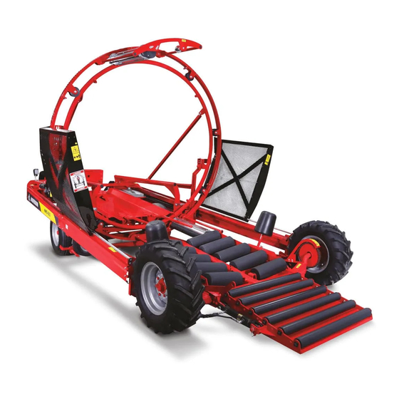
- Page 1 #404605-1 Round Bale Wrapper NWS-660(660E) Operator’s Manual 2010-2011...
- Page 3 For safe and proper functioning please: Read the manual. Follow the safety instructions. Follow the start-up steps given on the last page of your manual. In case of sale or transfer, give this manual to the new owner.
-
Page 4: Table Of Contents
Table of Contents 1 ANDERSON Limited Warranty................... 10 One-Year Limited Warranty..................10 Documents ......................10 Problem Resolution ....................10 Modifications......................10 Warranty Exemptions ....................12 Exclusive Remedy ....................12 2 Safety..........................13 Safe Operators......................13 Danger Zone......................13 Secure Attachment to the Tractor ................13 Dangerous Situations .................... - Page 5 Remote Control......................47 11.4 Remote Operation ....................48 Characteristics ......................48 Operation ........................ 50 Programming ......................50 11.5 Anderson Plastic Detector ..................54 12 Hoop ..........................56 12.1 Reassembling the Hoop ..................56 Outer Hoop......................56 Inner Hoop ......................56 12.2 Reassembly Instructions for Revolving Hoop ............
- Page 6 Figure 8.3 Gap ........................28 Figure 8.4 Transfer bar....................... 28 Figure 8.5 Stopper ......................29 Figure 8.6 Valve ......................... 29 Figure 8.7 Hoop actuator lever.................... 30 Figure 8.8 Pusher trigger adjustment rod................31 Figure 8.9 Pusher trigger ....................31 Figure 8.10 Trigger limit stop ....................32 Figure 8.11 Automatic system spring ...................
- Page 7 - Product model and serial number; - Purchase date and invoice number; - Dealer name, address, and telephone number and salesperson name; - Precise and detailed description of your problem. ANDERSON EQUIPMENT Address: 5125 de la Plaisance Chesterville (Québec) CANADA G0P 1J0 Email Service: service@anderson-equipment.com...
- Page 9 ANDERSON LIMITED WARRANTY FORM Warranty form must be completed and returned. Please fill in this form with information about your new machine. Please return this form to us in the 15 days following the date of delivery to validate your warranty. Details of the warranty provided can be found in the operator’s manual.
- Page 11 For your personal records, we recommend that you fill in this form with information about your machine. Type of Machine: Model: Options: Serial Number: Date of Sale to Customer: Customer Name: Customer Address: Customer Telephone Number: Dealer Name: Salesperson Name: Dealer Address: Salesperson Signature:...
-
Page 12: Anderson Limited Warranty
1 ANDERSON Limited Warranty One-Year Limited Warranty In the year following the purchase of a new machine, if your ANDERSON equipment fails to operate properly due to defective materials, manufacturing, or assembly, our company will furnish replacement parts and repair your machine free of charge. - Page 13 For all repair requests made to an Anderson dealer, you must furnish the date of sale, the serial number, the type of equipment and options, and the owner’s contact information.
-
Page 14: Warranty Exemptions
Except for conditions or warranties which may not be excluded by law, the selling dealer makes no warranty of its own on any item warranted by Anderson Equipment unless it delivers to the purchaser a separate written warranty document specifically warranting the item. The... -
Page 15: Safety
2 Safety Your ANDERSON bale wrapper was designed to reduce to a minimum the risks to the operator. However, it must be used only for the work it was designed for. Additionally, since it includes a powerful hydraulic system, moving metal parts, and a gasoline engine and all these elements can cause serious injury to humans or animals, it is strongly recommended to read and to closely adhere to the following guidelines. -
Page 16: Hydraulic Oil
Hydraulic Oil Any leak of pressurized oil can cause serious injuries. Do not use your hands to locate a leak, but rather an object such as a piece of cardboard. Stop the engine and release the pressure before disconnecting or reconnecting the lines. Firmly tighten all connections before restarting the engine or reapplying hydraulic pressure. -
Page 17: General Characteristics And Specifications
3 General Characteristics and Specifications Congratulations! You are now the owner of an ANDERSON bale wrapper, a high-quality machine designed for inline continuous wrapping of large round bales. This agricultural machine is carefully manufactured by our company to give you many years of reliable performance. -
Page 18: Moving The Bale Wrapper
4 Moving the Bale Wrapper Short Distances Your bale wrapper can be moved very short distances using its own traction. Start the engine and use the hydraulic control levers (Figure 4.1). According to the options available on your bale wrapper, there are 4 ways to start the HONDA engine: manual ignition, electronic ignition with key, electronic ignition with remote control, and electronic ignition using the same remote control as for remote steering. -
Page 19: Medium Distances
Medium Distances Your machine can be moved short and medium distances behind a tractor or truck. Use the hydraulic jack to raise the front of the bale wrapper and install the draw bar (Figure 4.3). Attach the machine and attach a security chain to the ring provided for this purpose on the draw bar. -
Page 20: Advice For Producing High-Quality Wrapped Fodder
40% less than for individual bale wrapping or bagging, all while creating the same airtight conditions necessary for high-quality silage. The savings that the ANDERSON bale wrapper will produce is an important addition to all the advantages mentioned above. -
Page 21: When Is The Best Time For Baling
When Is the Best Time for Baling? After the drying period, the decision of when to bale your fodder depends above all on the time when the amount of humidity in the cut hay has decreased just enough. If you want your fodder to stay good for at least a year, the ideal level of humidity is around 50% for both grasses and legumes, with a possible range of 40% to 55%. -
Page 22: Beginning Continuous Bale Wrapping
6 Beginning Continuous Bale Wrapping Before Beginning Check the level of oil in the hydraulic tank, as well as the level of fuel in the tank of the Honda engine. Also check the Honda engine’s oil level using the gauge at the base behind the engine (Figure 6.1). -
Page 23: Figure 6.3 Brake Pedal
To prevent the hoop from turning during installation, engage the hoop brake pedal, located to the left of the drive wheel (Figure 6.3). Figure 6.3 Brake pedal Remove the pin from the front roll support (Figure 6.4), slide the support forward, and, if applicable, remove the empty spool. -
Page 24: Installing The 2 Plastic Film Roll
Figure 6.5 Installing the plastic film roll Installing the 2 Plastic Film Roll Release the brake of the hoop wheel, turn the hoop 180 degrees, and reengage the brake. Repeat the preceding installation instructions. Put the screen back in place. Leaving the plastic rolls in the sun for an extended period of time before installation can cause the film to become soft. -
Page 25: Ground Level
Figure 6.6 Pusher trigger For bales more than 122 cm (4 feet) long, you should adjust the path of the pusher by moving the stopper (Figure 7.2) forward or backward so that the edge of the bale stops more or less in the center of the stretchers. -
Page 26: Hydraulic Brake
between the bale that has just been loaded and the bale already on the bale wrapper during a pusher cycle. Hydraulic Brake At this moment, you should also gradually adjust the front wheel drive’s hydraulic brake (Figure 4.1). This more or less blocks the front wheels so as to compress the continuous bale row and decrease as much as possible the air space between the bales. -
Page 27: Wrapping Settings
7 Wrapping Settings Adjusting the Number of Plastic Film Layers You already know that it is possible to increase the number of plastic film layers by moving the wrapping speed control lever to a higher number. Conversely, moving the speed control lever to a lower number increases the number of layers. -
Page 28: Adjusting The Hoop's Drive Wheel
Adjusting the Hoop’s Drive Wheel If the hoop slips or stops, you can increase the tension of the spring that holds the wheel in place. All you have to do is tighten the nut on the threaded rod, located above the spring to the left of the wheel (Figure 7.3). -
Page 29: Adjustment Procedures
8 Adjustment Procedures Factory-Made Automatic System: In Case of Problem Check Adjustments Follow steps (8.1)-(8.2)-(8.3)-(8.4)-(8.5). Refer to the numbers in the illustrations. Figure 8.1 Start pedal Press down on the start pedal located at the back of the bale wrapper, right next to the Honda gasoline engine (Figure 8.1 #1). -
Page 30: Figure 8.3 Gap
3/16’’ Figure 8.3 Gap If the automatic system is correctly adjusted, you should obtain a distance of 3/16’’ (Figure 8.3 #4) between the snap ring and the body of the valve. If you do not obtain a distance of 3/16’’, refer to the adjustment procedure that follows. Figure 8.4 Transfer bar To adjust the gap (Figure 8.3 #4) in the preceding illustration, you must unscrew the 2 carriage bolts (Figure 8.4 #5) and move the part (Figure 8.4#6) so as to obtain the necessary... -
Page 31: Adjusting The Hoop Release
Adjusting the Hoop Release Place the part (Figure 8.5 #10) at the 7 slot from the rear of the machine (Figure 8.5#11). Figure 8.5 Stopper Place the hoop speed control lever at position 0 (Figure 8.6 #12). Press the hydraulic stop button (Figure 8.6 #13). -
Page 32: Figure 8.7 Hoop Actuator Lever
Manually push the pointer toward the front of the machine (Figure 8.7 #14). Start the engine. Push down the pusher start pedal (Figure 8.1 #1). Stand beside the machine so that you can see the pointer and the actuator lever (Figure 8.7). Pull the hydraulic stop button (Figure 8.6 #13). -
Page 33: Adjusting The Pusher Trigger
Adjusting the Pusher Trigger Place the speed control lever at position 0 (Figure 8.6 #12). Push the hydraulic stop button (Figure 8.6 #13). Start the engine. Push down the pusher start pedal (Figure 8.1#1). Stand so that you can see the trigger (Figure 8.9 #17) and the pusher cross bar (Figure 8.9 #18). -
Page 34: Adjusting The Limit Stop
Adjusting the Limit Stop 8.10 The trigger (Figure 8.10#20) must be adjusted to about 3/4’’ from the pusher. 3/16’’ 3/4’’ Figure 8.10 Trigger limit stop 8.11 The spring attachment must be at an angle of about 45 degrees relative to the table (Figure 8.11 #21). -
Page 35: How To Finish A Continuous Bale Row
How to finish a continuous bale row 1- Wrap the last bale of the continuous bale row in a plastic bag and load it onto the bale wrapper. The wrapping cycle will take place. Do not forget to release the hydraulic brake (Figure 6.3). -
Page 36: Variation For Finishing A Continuous Bale Row
Figure 8.13 Unloading post 6- Once the pusher plate is located in the bale, start the engine. 7- By pushing on the start pedal located at the rear of the bale wrapper (Figure 8.14), you will start a pushing cycle. You must manually remove the unloading post (push forward) while the pusher is moving backward. -
Page 37: Maintenance And Storage
During maintenance, it is important to respect all safety rules. Grease Gun Lubrication Your ANDERSON bale wrapper must be lubricated with a grease gun every 200 bales in the places indicated by a yellow sticker. - The 2 front axles... - Page 38 The 2 front axles and chains The 2 rear axles Throttle lever...
- Page 39 Pusher frame Automatic system control Revolving core...
- Page 40 Stretcher Hoop wheel Hoop release...
-
Page 41: Cleaning
Cleaning Always keep the rollers of the plastic film stretcher and the rubber free roller clean and free of all hay or other residue to prevent these parts or the gears from jamming, breaking, or tearing the plastic film. Also remove regularly the hay that can get stuck in the axles and gears of the machine so as not to place needless strain on the hydraulic engines. -
Page 42: Troubleshooting
10 Troubleshooting Breakdown?!? You machine is functioning poorly or not at all?!? Before calling a technician, examine your machine and consult the table below to find a solution. If you are still not able to solve the problem yourself, ask for help from the customer service department of your agricultural dealer. - Page 43 The hoop speed control is improperly Move the control forward between adjusted. 2 and 10. Tighten the wheel spring. Check tire air pressure and adjust The drive wheel slides on the hoop. if necessary. Change the tire if it is worn out. 4.
- Page 44 The 12 V battery of the remote Change the battery or check the control has lost its charge or is connection. Next, press in disconnected. alternation on the right/left 10. The remote control direction buttons to reprogram for remote operation remote operation.
-
Page 45: Optional Equipment
11 OPTIONAL EQUIPMENT 11.1 Road Lights Two red tail lights inserted in the rear bumper for safe road transportation. Connect to the tractor or truck (Figure 11.1). Figure 11.1 Road lights... -
Page 46: Work Lights
11.2 Work Lights Two halogen lights installed on the cross bar on the right side of the machine to facilitate machine operation in the evening or at night. Connected to the machine’s electrical system (Figure 11.2)(Figure 11.3). Be aware that the Honda engine must be equipped with a minimum 10 amp alternator for this option to be successfully installed. -
Page 47: Remote Starter
11.3 Remote Starter Characteristics This electric starter system, also called an engine kill, can only start or stop the Honda gas engine. It includes a module that is installed on the interior of the rear chassis on the right side (Figure 11.5) and connected to the engine. -
Page 48: Figure 11.6 Remote Starter Connections
Black Black with white stripes Figure 11.6 Remote starter connections 9 for connecting the module to the engine: 1 – Keep the engine switch in OFF position during the entire procedure. 2 – Disconnect the positive terminal of the engine battery. 3 –... -
Page 49: Start Up
Figure 11.8 Remote starter connections 3 Start Up Do not forget to turn the engine key to ON before using your remote control. If you do not do this, the remote control will not work. You can leave the engine switch in ON position for several weeks without starting the engine. -
Page 50: Remote Operation
11.4 Remote Operation Characteristics Since February 2005, we are installing and offering a new remote operation system, which is more compact and performs better. A new direction valve with solenoid in back (Figure 11.9) replaces the regular direction valve to the right of the machine’s valve block. A small lever on this valve can also be used to manually control direction if necessary. -
Page 51: Figure 11.10 Remote Control For Remote Operation
Figure 11.10 Remote control for remote operation Figure 11.11 Remote operation module... -
Page 52: Operation
Operation Turn the module’s green button to ON (Figure 11.11). This button will blink while the remote control is starting the engine (Figure 11.10) and then will remain on. Press the right and left arrows to turn the machine. The hydraulic stop button will work if needed. If it is not used, the module will automatically shut off after a certain period of time in order to preserve the battery. -
Page 53: Figure 11.3 Electrical Diagram
CBK3SLKIG CBKCB10 CBKCB10 TSRC10 WITH 2 TSRC10 AVEC 2IÈME BIGGEST RING PLUS GRANDE (1/2”) BAGUE(1/2") Internal connections of NWS-660 control Title BRANCHEMENT INTERNE DU CONTROLE RB9000 Figure 11.13 Electrical diagram 2 GREEN ORANGE BLACK YELLOW Figure 11.14 Electrical connections 1... -
Page 54: Figure 11.15 Electrical Diagram 3
Connection for 1 double valve – 3 feet WHITE YELLOW MXL22-18-M4 2.75 (33")X LOOM .25 (1/4) 3X MXL22-18-MP 1X MXLB YELLOW BLACK CAB-4M-3-VAL WHITE Note: Note: Add label to this Ajouter l'étiquette connector. sur ce connecteur. BLACK VALVE CONNECTOR CONNECTEUR VALVE Figure 11.15 Electrical diagram 3 Note: Note:... -
Page 55: Figure 11.17 Electrical Diagram 5
ATTACH THE 2 WIRES ATTACHER LES DEUX FILS WITH AN AT-4-BLACK AT AVEC UNE AT-4-NOIR À 1" 1” FROM FUSE SUPPORT DU SUPPORT À FUSIBLE JUNCTION BETWEEN JONCTION ENTRE LE Starter and power cable for gasoline RED/GREEN WIRE FIL ROUGE/VERT ET AND FUSP-0.110- LE FUSP-0.110-FIL À... -
Page 56: Anderson Plastic Detector
11.5 Anderson Plastic Detector This equipment can be added to the Anderson NWS-660 bale wrapper. It stops the machine when the plastic film tears or runs out. The absence of plastic film causes a first mechanism (kit C) on the stretcher to move, activating a 2 system (kit B) on the hoop frame, which finally activates (kit A) the hydraulic stop. -
Page 57: Figure 11.19 Detector Parts (Kit A)
When you unwind the plastic film, it should hold the detector rod under tension. Repeat the same procedure with the second stretcher. Your detector is now ready to work. For more details see parts booklet. Figure 11.19 Detector parts (kit A) Figure 11.20 Detector parts (kit B) Figure 11.21 Detector parts (kit C) -
Page 58: Hoop
12 Hoop 12.1 Reassembling the Hoop Outer Hoop Place the 4 sections flat on the ground. Place a 3/8” wide metal spacer on the ground in the center of each section so that the sections are parallel to the ground. Each end piece is numbered from 1 to 4. -
Page 59: Reassembly Instructions For Revolving Hoop
12.2 Reassembly Instructions for Revolving Hoop You have received your machine assembled in the factory according to the illustration below (Erreur ! Source du renvoi introuvable.) and you want to reinstall the hoop in normal position. Here are the steps to follow: 1 –... - Page 61 Parts manual ROUND BALE WRAPPER NWS-660 (660E) ALWAYS KEEP THIS MANUAL WITH THE WRAPPER December 21, 2009...
- Page 63 Content 1 – General view P. 4 2 – Complete front section P. 5 3 – Frame front section P. 6 4 – Front gate P. 8 5 – Support of roller P. 9 6 – Front spindle P. 10 7 –...
- Page 64 P. 58 For any parts order, please use the parts manual to find the item(s) you need and contact your dealer to order it or contact us directly at : ANDERSON EQUIPMENT 5125 de la Plaisance Chesterville (Québec) CANADA G0P 1J0...
- Page 66 Support and spear Guard Round bale guide Table Front gate Right Fender Honda engine and battery Tow bar (hold on place) Brake and wheel drive for the hoop Anderson Group, 5125 de la Plaisance Chesterville (Québec) G0P 1J0 Email : service@grpanderson.com...
- Page 67 210143-2 COMPLETE FRONT FRAME 320039 HITCH PIN 467099 HYDRAULIC CYLINDER 467228 HYDRAULIC CYLINDER 320043 COTTER PIN 210832 ROLLER ASSEMBLY 210142-2 GATE LOCKING PIN DETAIL D DETAIL C Anderson Group, 5125 de la Plaisance Chesterville (Québec) G0P 1J0 Email : service@grpanderson.com...
- Page 68 3 - FRAME FRONT SECTION Anderson Group, 5125 de la Plaisance Chesterville (Québec) G0P 1J0 Email : service@grpanderson.com...
- Page 69 CYLINDER PLATE 301010 SPROCKET 210011-3 FRONT BRIDGE LOCK 469159 HYDRAULIC MOTOR 210015 HUB WITH SPROCKET 507016 WHEEL BOLT 500602 FLANGE BOLT 481503 TIRE AND RIM 210014 TRACTION CHAIN Anderson Group, 5125 de la Plaisance Chesterville (Québec) G0P 1J0 Email : service@grpanderson.com...
- Page 70 PARTS LIST ITEM PART DESCRIPTION 210012-1 FRONT GATE FRAME 210013 FRONT GATE ROLL LOCKING 279002 PLASTIC BUSHING 501022 FLANGE NUT 210802 GATE FRONT ROLL 500440 CARRIAGE BOLT Anderson Group, 5125 de la Plaisance Chesterville (Québec) G0P 1J0 Email : service@grpanderson.com...
- Page 71 5 - SUPPORT ROLLER PARTS LIST ITEM PART DESCRIPTION 325112 SUPPORT ROLLER 303045 BEARING 320006 RETAINING RING 320010 HITCH PIN 210526 SUPPORT ROLLER SHAFT 325107 Anderson Group, 5125 de la Plaisance Chesterville (Québec) G0P 1J0 Email : service@grpanderson.com...
- Page 72 303034 BEARING 303037 BEARING CUP 210147-1 RIGHT TRACTION SPINDLE 502011 FLAT WASHER 501076 CASTLE NUT 320020 COTTER PIN 481503 TIRE AND WHEEL RIM 210146-1 LEFT TRACTION SPINDLE Anderson Group, 5125 de la Plaisance Chesterville (Québec) G0P 1J0 Email : service@grpanderson.com...
- Page 73 COMPLETE ENGINE UNIT REAR BUMPER CENTRAL BEAM HOOP AND SPEAR SUPPORT RIGHT HOOP SUPPORT REINFORCEMENT REMOVABLE SPEAR AND SUPPORT COMPLETE AUTOMATIC SYSTEM COMPLETE DRIVE WHEEL LEFT HOOP SUPPORT Anderson Group, 5125 de la Plaisance Chesterville (Québec) G0P 1J0 Email : service@grpanderson.com...
- Page 74 8 - AUTOMATIC SYSTEM Anderson Group, 5125 de la Plaisance Chesterville (Québec) G0P 1J0 Email : service@grpanderson.com...
- Page 75 8 - AUTOMATIC SYSTEM Anderson Group, 5125 de la Plaisance Chesterville (Québec) G0P 1J0 Email : service@grpanderson.com...
- Page 76 8 - AUTOMATIC SYSTEM Anderson Group, 5125 de la Plaisance Chesterville (Québec) G0P 1J0 Email : service@grpanderson.com...
- Page 77 310014 SPRING 500443 CARRIAGE BOLT 502004 FLAT WASHER 500446 CARRIAGE BOLT 320025-2 QR PIN 210150 RACK IN PINION SUPPORT 210640 SPRING ATTACHMENT 500500 CARRIAGE BOLT 500088 BOLT Anderson Group, 5125 de la Plaisance Chesterville (Québec) G0P 1J0 Email : service@grpanderson.com...
- Page 78 HYDRAULIC FITTING 465003 DETENT KIT 451179 HYDRAULIC FITTING 451124 HYDRAULIC FITTING 450558 HYDRAULIC FITTING 451265 HYDRAULIC FITTING PARTS LIST ITEM PART DESCRIPTION 465001 HYDRAULIC VALVE 451229 HYDRAULIC FITTING Anderson Group, 5125 de la Plaisance Chesterville (Québec) G0P 1J0 Email : service@grpanderson.com...
- Page 79 STEERING AXLE BEAM 210049 DIRECTION ANGLE ARM 481507 TIRE AND RIM 467503 CYLINDER AXLE 467501 HAIR PIN 467215 HYDRAULIC CYLINDER 450711 HYDRAULIC FITTING 500285 BOLT DETAIL A Anderson Group, 5125 de la Plaisance Chesterville (Québec) G0P 1J0 Email : service@grpanderson.com...
- Page 80 CASTLE NUT PARTS LIST ITEM PART DESCRIPTION 481450 481002 HUB CAP 303500 DUST CAP 303501 BEARING 303099 BEARING 303037 ROLLING BEARING CAGE 303034 BEARING 507016 WHEEL BOLT Anderson Group, 5125 de la Plaisance Chesterville (Québec) G0P 1J0 Email : service@grpanderson.com...
- Page 81 HYDRAULIC FITTING 451097 HYDRAULIC FITTING 450712 HYDRAULIC FITTING 465878 CHECK VALVE 469158 HYDRAULIC MOTOR 502064 LOCK WASHER 500004-1 BOLT 481505 TIRE AND RIM 210203 HOOP WHEEL DRIVE SUPPORT Anderson Group, 5125 de la Plaisance Chesterville (Québec) G0P 1J0 Email : service@grpanderson.com...
- Page 82 PARTS LIST ITEM PART DESCRIPTION 210604 CENTRAL BEAM SUPPORT 210058-1 FRONT BALE GUIDE SUPPORT 500506 CARRIAGE BOLT 500510 CARRIAGE BOLT 501024 FLANGE NUT 320029-1 QR PIN 500177 BOLT Anderson Group, 5125 de la Plaisance Chesterville (Québec) G0P 1J0 Email : service@grpanderson.com...
- Page 84 13 - RIGHT SUPPORT HOOP Anderson Group, 5125 de la Plaisance Chesterville (Québec) G0P 1J0 Email : service@grpanderson.com...
- Page 85 502002 FLAT WASHER 500006 BOLT 210839 COVER 210138-1 EMERGENCY STOPPER 210840 SPACER PLATE 500010 BOLT 210154-1 RIGHT HOOP SUPPORT 500511 CARRIAGE BOLT 210207 RIGHT PUSHER CYLINDER SUPPORT Anderson Group, 5125 de la Plaisance Chesterville (Québec) G0P 1J0 Email : service@grpanderson.com...
- Page 86 13 - LEFT SUPPORT HOOP Anderson Group, 5125 de la Plaisance Chesterville (Québec) G0P 1J0 Email : service@grpanderson.com...
- Page 87 PIVOT PLATE 500510 CARRIAGE BOLT 210156 LEFT FRONT ATTACHMENT PLATE 500506 CARRIAGE BOLT 500500 CARRIAGE BOLT 210154-2 LEFT HOOP ATTACHMENT 500511 CARRIAGE BOLT 210208 LEFT PUSHER CYLINDER SUPPORT Anderson Group, 5125 de la Plaisance Chesterville (Québec) G0P 1J0 Email : service@grpanderson.com...
- Page 88 CARRIAGE BOLT 501024 FLANGE NUT 210158-2 REAR BUMPER 210159-1 COMPLETE THROTTLE 210209 REAR CYLINDER AXLE 320002 COTTER PIN 501034 NYLON NUT 320029-1 QR PIN 210168 BUMPER REINFORCMENT Anderson Group, 5125 de la Plaisance Chesterville (Québec) G0P 1J0 Email : service@grpanderson.com...
- Page 89 210624-2 ACTIVATION PLATE 501030 NYLON NUT 500004 BOLT 310015 SPRING 502002 FLAT WASHER 501021 FLANGE NUT 500006 BOLT 501020 FLANGE NUT 500360 CARRIAGE BOLT 320031 LOCK PIN Anderson Group, 5125 de la Plaisance Chesterville (Québec) G0P 1J0 Email : service@grpanderson.com...
- Page 90 322050 COUPLING 507003 ALLEN SET SCREW 468500 HYDRAULIC PUMP 500084 BOLT 451179 HYDRAULIC FITTING 500088 BOLT 451190 HYDRAULIC FITTING 315044 BATTERY-ENGINE WIRE 502004 FLAT WASHER 470015 OIL FILTER Anderson Group, 5125 de la Plaisance Chesterville (Québec) G0P 1J0 Email : service@grpanderson.com...
- Page 91 16 - COMPLETE SPEAR PARTS LIST ITEM PART DESCRIPTION 210619-1 SPEAR SUPPORT 210620-2 SPEAR 500510 CARRIAGE BOLT 501024 FLANGE NUT 500185 BOLT Anderson Group, 5125 de la Plaisance Chesterville (Québec) G0P 1J0 Email : service@grpanderson.com...
- Page 92 ITEM PART DESCRIPTION 210725-1 STOPPER 500500 CARRIAGE BOLT 500502 CARRIAGE BOLT 501024 FLANGE NUT 210197 REAR BEAM SUPPORT 450899 HYDRAULIC FITTING 450863 HYDRAULIC FITTING 210198 CENTRAL BEAM Anderson Group, 5125 de la Plaisance Chesterville (Québec) G0P 1J0 Email : service@grpanderson.com...
- Page 93 210085-1 SIDE REAR REINFORCMENT 210823 REMOTE STARTER SUPPORT 315052 REMOTE STARTER RECIEVER 500082 BOLT 315053 HAND HELD REMOTE 325115 RUBBER DOOR HOLDER 210844 RUBBER SUPPORT 500001 BOLT Anderson Group, 5125 de la Plaisance Chesterville (Québec) G0P 1J0 Email : service@grpanderson.com...
- Page 94 LEFT BALE GUIDE 210092-2 COMPLETE PUSHER FRAME 210200-2 LEFT PUSHER FRAME 210201-2 RIGHT PUSHER FRAME 210096 COMPLETE RIGHT FENDER 210679-1 COMPLETE RIGHT SHIELD 210680-1 COMPLETE LEFT SHIELD Anderson Group, 5125 de la Plaisance Chesterville (Québec) G0P 1J0 Email : service@grpanderson.com...
- Page 95 210103 LEFT FENDER JOINT 210104 REAR LEFT FENDER 210105 FRONT LEFT FENDER 500442 CARRIAGE BOLT 501022 FLANGE NUT 501024 FLANGE NUT 500440 CARRIAGE BOLT 501032 NYLON NUT Anderson Group, 5125 de la Plaisance Chesterville (Québec) G0P 1J0 Email : service@grpanderson.com...
- Page 96 21 - SUPPORT OF ROLL AND VALVE DETAIL A DETAIL B Anderson Group, 5125 de la Plaisance Chesterville (Québec) G0P 1J0 Email : service@grpanderson.com...
- Page 97 VALVE (NEXT PAGE) VALVE (NEXT PAGE) VALVE (NEXT PAGE) VALVE (NEXT PAGE) 319880 WORK LIGHT 315009-1 RECEIVER TAC-02 315080 BALE COUNTER 315080 WHIT BALLE CONTER 210550 RECEIVER SUPPORT Anderson Group, 5125 de la Plaisance Chesterville (Québec) G0P 1J0 Email : service@grpanderson.com...
- Page 98 HYDRAULIC FITTING 450242 HYDRAULIC FITTING 450542 HYDRAULIC FITTING 450994 HYDRAULIC FITTING 450022 HYDRAULIC FITTING 470010 PRESSURE GAUGE 450196 HYDRAULIC FITTING 450877 HYDRAULIC FITTING 465878 CHECK VALVE DETAIL C Anderson Group, 5125 de la Plaisance Chesterville (Québec) G0P 1J0 Email : service@grpanderson.com...
- Page 99 PARTS LIST ITEM PART DESCRIPTION 465983 SPEED CONTROL VALVE 450712 HYDRAULIC FITTING 450716 HYDRAULIC FITTING 465879 CHECK VALVE 450548 HYDRAULIC FITTING 450381 HYDRAULIC FITTING 450008 HYDRAULIC FITTING Anderson Group, 5125 de la Plaisance Chesterville (Québec) G0P 1J0 Email : service@grpanderson.com...
- Page 100 451123 HYDRAULIC FITTING 451172 HYDRAULIC FITTING 450972 HYDRAULIC FITTING 465975 HYDRAULIC VALVE (3 SECTION)MAN. 465984-0 HYDRAULIC VALVE (4 SECTION)ELEC. 465985-0 HYDRAULIC VALVE (4 SECTION)MAN. 451227 HYDRAULIC FITTING Anderson Group, 5125 de la Plaisance Chesterville (Québec) G0P 1J0 Email : service@grpanderson.com...
- Page 101 FLANGE NUT 210181-1 WEDGE SUPPORT 210182 WEDGE 210183 CYLINDER LOCK SUPPORT 500026 BOLT 500177 BOLT 500501 CARRIAGE BOLT 500500 CARRIAGE BOLT 210566-2 COMPLET PUSHER DETAIL B DETAIL A Anderson Group, 5125 de la Plaisance Chesterville (Québec) G0P 1J0 Email : service@grpanderson.com...
- Page 102 500004 BOLT 501030 NYLON NUT 210816 STOPPER 306022 JACK AXLE 210792 ADJUSTMENT ROD 210791 JACK SUPPORT 501005 501042 NYLON NUT 210567-2 PUSHER PLATE DETAIL D SCALE .15 Anderson Group, 5125 de la Plaisance Chesterville (Québec) G0P 1J0 Email : service@grpanderson.com...
- Page 103 500230 BOLT 210572-2 PUSHER FRAME 500501 CARRIAGE BOLT 501024 FLANGE NUT 500187 BOLT 501032 NYLON NUT 500100 BOLT 320023 LOCK PIN 210724-2 COMPLETE SWIVEL HEART DETAIL C Anderson Group, 5125 de la Plaisance Chesterville (Québec) G0P 1J0 Email : service@grpanderson.com...
- Page 104 DESCRIPTION 500442 CARRIAGE BOLT 501022 FLANGE NUT 210185 INSIDE HOOP SECTION 210154-1 RIGHT HOOP SECTION ATTACHMENT 210187 HOOP SECTION ATTACHMENT 210154-2 LEFT HOOP SECTION ATTACHMENT DETAIL A Anderson Group, 5125 de la Plaisance Chesterville (Québec) G0P 1J0 Email : service@grpanderson.com...
- Page 105 24 - OUTSIDE ROLL PARTS LIST ITEM PART DESCRIPTION 210189-1 HOOP SECTION 501022 FLANGE NUT 500442 CARRIAGE BOLT 210188-1 HOOP SECTION STETCHER FRAME DETAIL B Anderson Group, 5125 de la Plaisance Chesterville (Québec) G0P 1J0 Email : service@grpanderson.com...
- Page 106 210206 STRETCHER FRAME 322100 HOOP WHEEL AND BOLT COME WHIT WHEEL HALF NYLON NUT COME WHIT WHEEL BOLT 500175 BOLT 501004 500173 BOLT DETAIL E DETAIL F Anderson Group, 5125 de la Plaisance Chesterville (Québec) G0P 1J0 Email : service@grpanderson.com...
- Page 108 25 - STRETCHER RUBBER ROLLER STRETCHER Anderson Group, 5125 de la Plaisance Chesterville (Québec) G0P 1J0 Email : service@grpanderson.com...
- Page 109 BEARING CUP 210589 COVER 501030 NYLON NUT 210590 WASHER 501022 FLANGE NUT 501020 FLANGE NUT 304005 SPRING 500004 BOLT 501000 500008 BOLT 500017 BOLT 303018 BEARING 224069 ROLL Anderson Group, 5125 de la Plaisance Chesterville (Québec) G0P 1J0 Email : service@grpanderson.com...
- Page 110 DESCRIPTION 303012 BEARING 320028 RETAINING RING 308005 210721 ADJUSTABLE PIN 501030 NYLON NUT 320027 RETAINING RING 279007 PLASTIC ROLL HOLDER 210592 WASHER 500006 BOLT 320039 HITCH PIN Anderson Group, 5125 de la Plaisance Chesterville (Québec) G0P 1J0 Email : service@grpanderson.com...
- Page 111 26 - ROLL SUPPORT PARTS LIST ITEM PART DESCRIPTION 501036 NYLON NUT 303012 BEARING 320027 RETAINING RING 279007 PLASTIC ROLL HOLDER 500297 BOLT Anderson Group, 5125 de la Plaisance Chesterville (Québec) G0P 1J0 Email : service@grpanderson.com...
- Page 112 DESCRIPTION 279001 PLASTIC BUSHING 210681-1 SHIELD 210683-1 SHIELD SUPPORT 500602 FLANGE BOLT 501032 NYLON NUT 210682 FIXED SHIELD ATTACHMENT 500006 BOLT DETAIL B DETAIL A DETAIL C Anderson Group, 5125 de la Plaisance Chesterville (Québec) G0P 1J0 Email : service@grpanderson.com...
- Page 113 27 - HOOP SHIELD PARTS LIST ITEM PART DESCRIPTION 501020 FLANGE NUT 500006 BOLT 210755 SHIELD HANDLE 210809 SHIELD LOCK 500004 BOLT 304021 SPRING 210831 LOCK Anderson Group, 5125 de la Plaisance Chesterville (Québec) G0P 1J0 Email : service@grpanderson.com...
- Page 115 INSIDE HALF MOON SUPPORT 210794 OUTSIDE HALF MOON SUPPORT 210795 THREADED ROD 210805 PLASTIC TUBE 500004 BOLT 210797 TRIPPING PLATE 304022 SPRING 501020 FLANGE NUT 501030 NYLON NUT Anderson Group, 5125 de la Plaisance Chesterville (Québec) G0P 1J0 Email : service@grpanderson.com...
- Page 116 29-DIAGRAMME HYDRAULIQUE NWS-660E / NWS-660E HYDRAULIC DIAGRAM CRIC HYDRAULIQUE CYLINDRE DE CONDUITE HYDRAULIC JACK STEERING CYLINDER PONT AVANT TAIL GATE 2 X 7238-8 BOUCHON 2 X 7238-8 BOUCHON 5405-6-6 5405-6-6 5405-6-8 5205-6-8 2 X 5405-6-6 33-29 33-26 53-77 33-34 33-35 PA / FB MOTEUR CERCEAU CONTRÔLEUR DE VITESSE (CERCEAU)
- Page 117 29-DIAGRAMME HYDRAULIQUE NWS-660E / NWS-660E HYDRAULIC DIAGRAM LISTE DE PIÈCES ITEM DESCRIPTION FRANÇAISE ENGLISH DESCRIPTION QTÉ-QT PIÈCE/PAR 210749 BOYAU 33-10 HOSE 33-10 210748 BOYAU 33-11 HOSE 33-11 210753 BOYAU 33-12 HOSE 33-12 210752-1 BOYAU 33-13 HOSE 33-13 210751-1 BOYAU 33-14 HOSE 33-14 210686-2 BOYAU 33-19...
Need help?
Do you have a question about the NWS-660 and is the answer not in the manual?
Questions and answers