Table of Contents
Advertisement
Quick Links
Advertisement
Table of Contents

Related Manuals for Ublox C102-F9R


Summary of Contents for Ublox C102-F9R
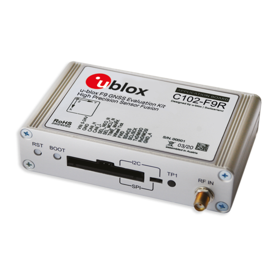
- Page 1 C102-F9R Application board User guide Abstract This document describes the structure and use of the C102-F9R and provides information for evaluating and testing u-blox F9 high precision sensor fusion positioning technology. UBX-20029244 - R03 C1-Public www.u-blox.com...
-
Page 2: Document Information
C102-F9R - User guide Document information Title C102-F9R Subtitle Application board Document type User guide Document number UBX-20029244 Revision and date 29-Oct-2020 Disclosure Restriction C1-Public This document applies to the following products: Product name Type number Firmware version PCN reference... -
Page 3: Table Of Contents
C102-F9R - User guide Contents Document information ..........................2 Contents ................................3 Introduction ............................. 5 1.1 Highlights ..............................5 1.2 Kit includes ..............................5 1.3 System requirements ..........................5 1.4 Evaluation steps ............................5 Device description ..........................6 2.1 USB................................. 6 2.2 UART ................................ - Page 4 C102-F9R - User guide B.2.2 Single speed ..........................16 B.2.3 Signed speed ..........................17 B.2.4 Offset speed ..........................17 Step-by-step example ........................18 Schematic ............................. 25 Related documents ........................... 31 Revision history ............................31 Contact ................................32 UBX-20029244 - R03...
-
Page 5: Introduction
C102-F9R - User guide Introduction The C102-F9R application board can be used to evaluate and test the high precision sensor fusion positioning technology of the ZED-F9R module. The built-in USB interface provides both power supply and a high-speed communications interface. The device is compact, and it provides a flexible and user-friendly interface between the GNSS module and test vehicles. -
Page 6: Device Description
C102-F9R - User guide Device description 2.1 USB A USB 2.0-compatible serial port is featured for data communication and power supply. USB drivers are installed automatically through Windows update. 2.2 UART The unit includes an RS-232 port which can be dynamically connected to the UARTs of the ZED-F9R module or the MCU. -
Page 7: 10-Pin Rear Connector
C102-F9R - User guide 2.5 10-pin rear connector This connector is used for updating the MCU firmware. See section 4.5 for more information. 2.6 Reset and safe boot buttons The reset button on the front panel resets the unit. The safe boot button is used to set the unit in safe boot mode. In this mode the receiver executes only the minimal functionality, such as updating new firmware into the SQI flash. -
Page 8: Setting Up
C102-F9R - User guide Setting up 3.1 Preparation ADR requires odometer sensor input from the vehicle reference point (VRP), that is, wheel ticks or speed, and direction. The following options are available: 1. WHEELTICK and DIRECTION pins 2. UBX-ESF-MEAS messages 3. -
Page 9: Configuring The Device
C102-F9R - User guide Alternatively, host interface can be established via UART pins on the front connector or the RS-232 connector. In this case, power must be provided via USB or the VIN and GND pins on the front connector. -
Page 10: Configurable Can Interface
C102-F9R - User guide Configurable CAN interface The device has a configurable high-speed CAN (ISO 11898-2) interface. The on-board MCU converts the configured CAN messages into UBX-ESF-MEAS messages which are sent to the receiver via I2C. 4.1 Valid configurations The CAN interface supports the following configurations: •... -
Page 11: Configuration Parameters
C102-F9R - User guide The numbers in the list below refer to Figure 1: • 1: Select the blue buttons in the middle to generate messages. • 2: Fill these fields for CONFIG SET messages. • 3: The generated message is displayed in the text field at the bottom. It is automatically copied to the clipboard. - Page 12 C102-F9R - User guide Power on the device. The following startup message should be displayed in the terminal window: 4. Setting up the configurable CAN feature: 4.1. Open the RealTerm Send tab. 4.2. Generate CONFIG SET message(s) in the MSG tool.
-
Page 13: Updating The Mcu Firmware
C102-F9R - User guide A configuration entry can be overwritten by sending a new CONFIG SET message with the same unit and source. ☞ All configuration entries can be deleted with the CONFIG CLEAR message. 4.5 Updating the MCU firmware New MCU firmware and corresponding tool versions may be released e.g. -
Page 14: Appendix
C102-F9R - User guide Appendix A.1 CAN termination The CAN bus is terminated by including the jumper circled in Figure 2. The jumper is included by default. If the termination needs to be removed, open the enclosure and remove the jumper. -
Page 15: Single Tick And Direction
C102-F9R - User guide byte/bit The following CONFIG SET messages are generated for this configuration: • RR: 0x43 0xa2 0x11 0x13 0x03 0x23 0x01 0x00 0x00 0x08 0x00 0x28 0x10 0x00 0x00 0x00 0x00 0xff 0xff 0xe8 0x03 0x34 0x01 0xa9 0xa8 •... -
Page 16: Speed Configurations
C102-F9R - User guide B.2 Speed configurations B.2.1 Two rear wheels and direction This configuration uses speed from two rear wheels and a separate direction signal. The configuration entries are described in the tables below. Startbit Length Byte order Value type... -
Page 17: Signed Speed
C102-F9R - User guide The following CONFIG SET messages are generated for this configuration: • speed: 0x43 0xa2 0x11 0x13 0x03 0x23 0x01 0x00 0x00 0x08 0x00 0x18 0x08 0x00 0x00 0x00 0x00 0xff 0x00 0xe8 0x03 0x4a 0x00 0xa7 0xc0 •... -
Page 18: C Step-By-Step Example
C102-F9R - User guide The following CONFIG SET messages are generated for this configuration: • RR: 0x43 0xa2 0x11 0x13 0x03 0x23 0x01 0x00 0x00 0x08 0x00 0x10 0x10 0x88 0x13 0x78 0xec 0x77 0xec 0x0a 0x00 0x3a 0x00 0x19 0xb2 •... - Page 19 C102-F9R - User guide 7. Update ZED-F9R if necessary (Tools > Firmware Update). UBX-20029244 - R03 Appendix Page 19 of 32 C1-Public...
- Page 20 C102-F9R - User guide Configuring ZED-F9R ZED-F9R configuration can be set with UBX-CFG-VALSET message and the appropriate configuration keys. 8. Disable output messages on I2C (MCU is connected to I2C): CFG-I2COUTPROT-UBX = false CFG-I2COUTPROT-NMEA = false 9. Enable automatic alignment:...
- Page 21 C102-F9R - User guide UBX-20029244 - R03 Appendix Page 21 of 32 C1-Public...
- Page 22 C102-F9R - User guide Configuring the CAN interface in RealTerm 1. Open RealTerm. 2. Select the Port tab. 3. Select the PC port corresponding to the MCU UART. 4. Set baud rate to 115200. 5. Restart the C100. 6. MCU startup dialog should appear in the terminal.
- Page 23 C102-F9R - User guide Generating the CONFIG SET strings with the MSG tool From B.1.1: Startbit Length Byte order Value type Factor Offset Unit Source big-endian unsigned 65535 tick big-endian unsigned 65535 tick big-endian unsigned direction direction 7. Use the MSG tool to generate the CONFIG SET messages.
- Page 24 C102-F9R - User guide Sending CONFIG SET strings to MCU: 8. Open RealTerm. 9. Select the Send tab. 10. Copy and paste the rear-right wheel tick CONFIG SET string to the RealTerm text box. 11. Select the Send Numbers button.
-
Page 25: D Schematic
17. Fix status can be monitored with the docking windows > data view. D Schematic The following pages include the complete schematic for the C102-F9R board. Note that the GNSS module in the schematic is F9K, but otherwise the schematic is accurate. - Page 26 C102-F9R - User guide UBX-20029244 - R03 Appendix Page 26 of 32 C1-Public...
- Page 27 C102-F9R - User guide UBX-20029244 - R03 Appendix Page 27 of 32 C1-Public...
- Page 28 C102-F9R - User guide UBX-20029244 - R03 Appendix Page 28 of 32 C1-Public...
- Page 29 C102-F9R - User guide UBX-20029244 - R03 Appendix Page 29 of 32 C1-Public...
- Page 30 C102-F9R - User guide UBX-20029244 - R03 Appendix Page 30 of 32 C1-Public...
-
Page 31: Related Documents
C102-F9R - User guide Related documents [1] ZED-F9R Integration manual, UBX-20039643 [2] ZED-F9R Interface description, UBX-19056845 [3] u-center user guide, UBX-13005250 [4] RealTerm Serial Terminal, https://realterm.sourceforge.io/ [5] Silicon Labs 8-bit Microcontroller Software, https://www.silabs.com/products/development- tools/software/8-bit-8051-microcontroller-software [6] Silicon Labs 8-bit USB Debug Adapter, https://www.silabs.com/development-tools/mcu/8-bit/8-... -
Page 32: Ubx-20029244 - R03
C102-F9R - User guide Contact For complete contact information, visit us at www.u-blox.com. u-blox Offices North, Central and South America Headquarters Asia, Australia, Pacific Europe, Middle East, Africa u-blox America, Inc. u-blox Singapore Pte. Ltd. u-blox AG Phone: +1 703 483 3180...
Need help?
Do you have a question about the C102-F9R and is the answer not in the manual?
Questions and answers