Table of Contents
Advertisement
Quick Links
Advertisement
Table of Contents

Related Manuals for Ublox C93-M8E


Summary of Contents for Ublox C93-M8E
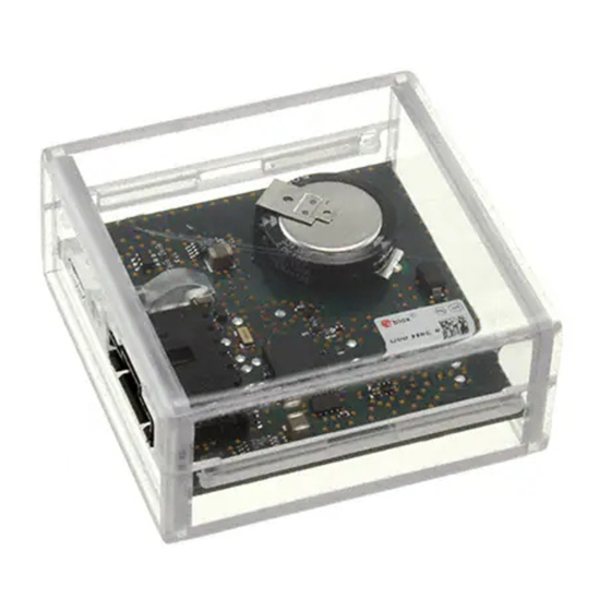
- Page 1 C93-M8E Application Board User Guide Abstract This document describes the structure and use of the C93-M8E application board and provides information for evaluating and testing u-blox M8 Untethered Dead Reckoning (UDR) positioning technology. www.u-blox.com UBX-15031067 - R03...
-
Page 2: Document Information
C93-M8E - User Guide Document Information Title C93-M8E Subtitle User Guide Document type User Guide Document number UBX-15031067 Revision and date 12-Dec-2018 Disclosure Restriction Early Production Information This document applies to the following products: Product name Type number ROM/FLASH version... -
Page 3: Table Of Contents
Contents Document Information ..........................2 Contents ................................3 Product description ..........................4 1.1 Overview ................................ 4 1.2 C93-M8E package includes ........................4 1.3 Evaluation software ............................ 4 1.4 System requirements ..........................4 Specifications ............................5 Device description ..........................6 3.1 Interface connection and measurement ....................6 3.2 Integrated GNSS antenna ......................... -
Page 4: Product Description
The C93-M8E is compact, and ideally suited for use in laboratories and vehicles. It can be used directly with a PDA or a notebook PC via its USB interface. Schematics and layouts are available, allowing the C93-M8E to be used as a basis for customer designs. -
Page 5: Specifications
C93-M8E - User Guide Specifications Parameter Specification 1 micro USB V2.0 Extra connectors connection pins for UART communication, 3.3 V Dimensions 49 x 49 x 20 mm Power Supply 5V via USB or external powered via extra power supply pin 1 (VCC) and common... -
Page 6: Device Description
Figure 1: Connecting the unit for power supply and communication 3.2 Integrated GNSS antenna The C93-M8E includes an 18 mm patch type GNSS antenna. The PCB design allows for patch antennas of up to 25 mm to be fitted (soldering required). -
Page 7: Pin Header
A micro USB V2.0 compatible port is featured for data communication and power supply. 3.3.2 Pin header The C93-M8E application board includes a 6-pin latching connector from the TE Connectivity AMPMODU MTE series. Mating cable receptacles from this series include part numbers 5-103960- 5 and 5-103957-5. -
Page 8: Setting Up
4.1.1 Mounting the C93-M8E The C93-M8E application board should be firmly attached to the car body so as to avoid any movement or vibration with respect to the car body. The application board should not be attached to any “live” (unsprung) part of the vehicle’s suspension. Often it is enough to use strong double sided tape or Velcro tape glued to the bottom of the C93-M8E casing. -
Page 9: Recommended Configuration
• Signal Attenuation Compensation: For installations where the signals are attenuated due to the C93-M8E placement, the signal attenuation compensation feature can be used to restore normal performance. There are three possible modes: Disabled: no signal attenuation compensation is performed... - Page 10 C93-M8E - User Guide Figure 4: Screenshot of u-center showing the INITIALIZING mode in UBX-ESF-STATUS message 4.2.2.2 Fusion Mode Once the initialization phase is achieved, the receiver enters navigation mode and starts to compute combined GNSS/Dead-reckoning fixes and to calibrate the sensor required for computing the fused navigation solution.
-
Page 11: Accelerated Initialization And Calibration Procedure
C93-M8E - User Guide Figure 6: Screenshot of u-center showing the sensor calibration as CALIBRATED 4.3 Accelerated Initialization and Calibration Procedure This section describes how to perform fast initialization and calibration of the UDR receiver for the purpose of evaluation. -
Page 12: Test Drives
C93-M8E - User Guide Test Drives ☞ Before testing can be done, make sure that the calibration has been completed according to chapter 4. We recommend recording and archiving the data of your test drives. You can enable additional debug messages by clicking the Debug button, and then clicking the Record button (see Figure 7). -
Page 13: Block Diagram
Block diagram 50 Ω PATCH LNA + SAW ANTENNA FLASH EVA-M8E UART BACKUP Pin header 1.65 V–3.6 V SENSORS Power USB (5V) regulator Figure 9: C93-M8E block diagram UBX-15031067 - R03 Early Production Information Block diagram Page 13 of 21... -
Page 14: Board Layout
C93-M8E - User Guide Board layout Figure 10 shows the C93-M8E board layout. See Table 4 for the application board component list. Figure 10: C93-M8E layout: Top and Bottom UBX-15031067 - R03 Early Production Information Board layout Page 14 of 21... - Page 15 LOW NOISE AMPLIFIER GAAS MMIC 1.575 GHZ 1.5V-3.6V JRC EPFFP6-A2 3.6V -40/+85C TINY LOGIC UHS BUFFER OE_N ACTIVE LOW FAIRCHILD NC7SZ125 SC70 CRYSTAL CL=7PF MICRO CRYSTAL CC7 GOLD TERMINATION 32.768KHZ 100PPM -40/+85C Table 4: C93-M8E component list UBX-15031067 - R03 Early Production Information...
-
Page 16: Schematic
C93-M8E - User Guide Schematic Figure 11: Schematic C93-M8E UBX-15031067 - R03 Early Production Information Schematic Page 16 of 21... -
Page 17: Troubleshooting
C93-M8E - User Guide Troubleshooting My application (e.g. u-center) does not receive anything Check whether the blue LED on the application board is blinking. Also make sure that the USB cable is properly connected to the application board and the PC. By default, the application board outputs NMEA protocol on Serial Port 1 at 9600 Bd, or on the USB. - Page 18 The C93-M8E does not meet the TTFF specification Make sure the C93-M8E has a good sky view. An obstructed view leads to prolonged startup times. In a well-designed system, the average of the C/No ratio of high elevation satellites should be in the range of 40 dBHz to about 50 dBHz.
-
Page 19: Common Evaluation Pitfalls
C93-M8E - User Guide 10 Common evaluation pitfalls • A parameter may have the same name but a different definition. GNSS receivers may have a similar size, price and power consumption but can still have different functionalities (e.g. no support for passive antennas, different temperature range). Also, the definitions of hot, warm, and cold start times may differ between suppliers. -
Page 20: Related Documents
C93-M8E - User Guide Related documents [1] EVA-M8E Data Sheet, Docu. No UBX-15028061 [2] EVA-M8E Hardware Integration Manual, Docu. No. UBX-15028542 [3] NEO-M8U Data Sheet, Docu. No 15015679 [4] NEO-M8U Hardware Integration Manual, Docu. No. UBX-15016700 [5] u-blox 8 / u-blox M8 Receiver Description including Protocol Specification (Public version), Docu. -
Page 21: Contact
C93-M8E - User Guide Contact For complete contact information, visit us at www.u-blox.com. u-blox Offices North, Central and South America Headquarters Asia, Australia, Pacific Europe, Middle East, Africa u-blox America, Inc. u-blox Singapore Pte. Ltd. u-blox AG Phone: +1 703 483 3180...
Need help?
Do you have a question about the C93-M8E and is the answer not in the manual?
Questions and answers