Advertisement
Quick Links
Advertisement

Related Manuals for Ublox C94-M8P


Summary of Contents for Ublox C94-M8P
- Page 1 C94-M8P Application Board Setup Guide locate, communicate, accelerate UBX-16009722 – R02...
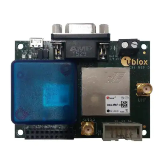
- Page 2 C94-M8P Board Connections and Interfaces • J1: RS232 – UART M8P/Radio • J2: USB – M8P • J3: External battery / DC connector • J6: Debugger interface for radio module • J8: UART & GNSS features • Geofence and RTK status •...
- Page 3 Setting up the C94-M8P Two C94-M8P boards – the “Base” and the “Rover” – need to be set up: Connect the UHF whip antenna to the SMA connector “UHF” Connect the GNSS patch antenna to the SMA connector ”GNSS” Connect the USB port on the board to a PC (for power and configuration) Slide 3 ©...
- Page 4 Preparing to Configure the C94-M8P To configure your C94-M8P kit you need to first: • Download the latest u-center from https://www.u-blox.com/en/product/u-center-windows Slide 4 © u-blox AG...
- Page 5 Updating firmware on C94-M8P Before starting the evaluation, check that the application boards are using the latest firmware (currently HPG 1.40). Information on the latest firmware is published on the u-blox web site. To update the firmware, follow the steps described in the u-center User Guide, chapter 8.1, Firmware update.
-
Page 6: Configuring The Base Station
Configuring the Base Station The two boards are identical. Select one board to act as a “Base Station”. The next slides will guide you through the steps needed to configure the Base Station There are three steps to configure the Base Station: Set the position, by having the Base Station do one of the following: survey-in its coordinates be configured with pre-surveyed coordinates... - Page 7 Step 1 – The Base Station Coordinates Use UBX-CFG-TMODE3 to: • Begin a self survey • Use, for example, 5 minutes and 2 meters as targets. • With a good antenna in a friendly multipath environment you can reach 1 meter with a 10-15 min observation time.
- Page 8 Step 1 – The Base Station Coordinates • The UBX-NAV-SVIN message allows you to monitor the survey-in process. • Self survey finishes when the accuracy AND time limit are satisfied. An operating Base Station indicates its Fix Mode as “TIME”. Note that you might have to disable NMEA messages to see this...
- Page 9 Step 2 – Base Station Radio Link • Use UBX-CFG-PRT to specify that only RTCM3 data is output on UART1. Slide 9 © u-blox AG...
- Page 10 Step 3 – Selecting RTCM messages • Use UBX-CFG-MSG to specify that these three RTCM3 messages are output on UART1. • 1005 (Station coordinates) • 1077 (GPS observations), and • 1087 (GLONASS observations) • 1230 (GLONASS code-phase biases) For a GPS/BeiDou setup or moving baseline applications, refer to the User Guide (UBX-15031066). Slide 10 ©...
- Page 11 Rover Setup Overview • Steps needed to set up the Rover Configure radio link A Rover that receives RTCM messages will automatically go into RTK operational mode, and no further configurations are needed. Slide 11 © u-blox AG...
- Page 12 Step 1 – Rover end Radio Link • Use UBX-CFG-PRT to ensure that UART1 is set up to receive RTCM3 corrections, and that no data is sent out (Protocol out: “none”). Slide 12 © u-blox AG...
- Page 13 Rover Operation • A Rover that receives RTCM corrections will automatically apply these and will: Immediately go into an RTK FLOAT mode Go into RTK FIXED mode once it has resolved the carrier ambiguities START Slide 13 © u-blox AG...
- Page 14 Important Note on Antennas • RTK technology depends on continuous carrier phase tracking, and therefore it is most important that: • Rover and Base antennas use ground planes • The roof of a car can serve as an excellent ground plane when the patch antenna is placed in the middle of the roof •...
-
Page 15: Notes On Usage
Notes on Usage The C94-M8P kit contains two boards configured to work as a pair • The default radio configuration supports one Base station transmitting to one Rover, and no other Base stations must be transmitting in the area. For other setups, please refer to the User Guide. - Page 16 Notes on the LEDs • Blue LED is blinking when there is a GNSS position fix (TIMEPULSE) • If there is no GNSS fix, the LED will light up without flashing • Green LED indicates the RTK status. • LED flashes in float mode and stays on in fix mode.
- Page 17 • C94-M8P User Guide (UBX-15031066) • C94-M8P-1-10/11 for China (433 MHz) • C94-M8P-2-10 /11for USA and Canada (915 MHz) • C94-M8P-3-10/11 for Europe (433 MHz) • C94-M8P-4-10/11 for Japan (920 Mhz) • Note that the connectors differ from the older -00 variants. Please refer to the last two slides for more connector information.
- Page 18 C94-M8P-B Board Connections and Interfaces • J1: RS232 – UART M8P/Radio • J2: USB – M8P • J3: External battery / DC connector • J4: UART interface • J6: Debugger interface for radio module • J8:Test & Production interface •...
- Page 19 C94-M8P-B Notes on the LEDs • Red LED blinking when the radio module is transmitting • Green LED blinking when radio module ready to receive and on when link established • Blue LED blinking when there is a GNSS position fix (TIMEPULSE) •...
Need help?
Do you have a question about the C94-M8P and is the answer not in the manual?
Questions and answers