Table of Contents
Advertisement
Quick Links
EVK-M8GZOE
Evaluation Kit
User Guide
Abstract
This document describes the structure and use of the EVK-M8GZOE
evaluation kit and provides information for evaluating and testing the
u-blox ZOE-M8G GNSS module. EVK-M8GZOE is also suitable to evaluate
the GNSS performance of ZOE-M8Q module.
www.u-blox.com
UBX-16030132 - R03
Advertisement
Table of Contents

Related Manuals for Ublox EVK-M8GZOE


Summary of Contents for Ublox EVK-M8GZOE
-
Page 1: Evaluation Kit
Evaluation Kit User Guide Abstract This document describes the structure and use of the EVK-M8GZOE evaluation kit and provides information for evaluating and testing the u-blox ZOE-M8G GNSS module. EVK-M8GZOE is also suitable to evaluate the GNSS performance of ZOE-M8Q module. - Page 2 Document contains the final product specification. European Union regulatory compliance EVK-M8GZOE complies with all relevant requirements for RED 2014/53/EU. The EVK-M8GZOE Declaration of Conformity (DoC) is available at www.u-blox.com (Support --> Product Resources --> Conformity Declaration). This document applies to the following products:...
-
Page 3: Preface
An index finger points out key information pertaining to device operation and performance. Warnings and certifications EVK-M8GZOE is an Electrostatic Sensitive Device (ESD). CAUTION! RISK OF SHORT CIRCUIT OF THE BATTERY WHEN TOUCHING IT WITH CONDUCTING PARTS. IN THE UNLIKELY EVENT OF A FAILURE IN THE INTERNAL PROTECTION CIRCUITRY THERE IS A RISK OF AN EXPLOSION WHEN CHARGING FULLY OR PARTIALLY DISCHARGED BATTERIES. -
Page 4: Table Of Contents
EVK-M8GZOE User Guide Contents Preface ..........................3 Using this guide ............................... 3 Warnings and certifications ..........................3 Contents ..........................4 Product description ...................... 6 Overview .............................. 6 1.1.1 Evaluation kit versions ........................6 1.1.2 Features ............................6 Kit includes ............................6 Software and documentation ....................... - Page 5 EVK-M8GZOE User Guide Measuring current consumption (ZOE-M8G only) ........... 16 Basic measurements with the shunt resistors ..................16 5.1.1 ZOE-M8G VCC current ........................ 17 5.1.2 ZOE-M8G V_BCKP current ......................18 5.1.3 ZOE-M8G optional Flash and logic current .................. 18 Measurement with an external current measuring power supply ............19 Testing Power Save Mode ..................
-
Page 6: Product Description
Active GNSS antenna with a 3 m cable USB cable A plastic cap is attached on the top of the GNSS S-LGA Module in EVK-M8GZOE. The purpose of the cap is to prevent air flow at ZOE-M8G. UBX-16030132 - R03... -
Page 7: Software And Documentation
EVK-M8GZOE User Guide 1.3 Software and documentation The EVK-M8GZOE installation software and documentation can be downloaded from the Web. EVK-M8GZOE Quick Start Guide [5] is available from http://start.u-blox.com u-center GNSS evaluation software and Windows driver for the evaluation board are available from web. See section 3.1 for details. -
Page 8: Specifications
Table 2: EVK-M8GZOE specification 2.1 Safety precautions EVK-M8GZOE must be supplied by an external limited power source in compliance with the clause 2.5 of the standard IEC 60950-1. In addition to external limited power source, only Separated or Safety Extra-Low Voltage (SELV) circuits are to be connected to the evalkit including interfaces and antennas. -
Page 9: Getting Started
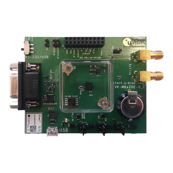
3.2 Hardware installation This section describes the evaluation board connectors and configuration settings that are required to get started. Figure 1 shows an overview of EVK-M8GZOE board and its connectors. Figure 1: Getting started overview 1. Make sure the “Interface Switch” is at RS-232 / USB side (and not SPI side). -
Page 10: Interface Default Configuration
EVK-M8GZOE User Guide If an RS-232 interface is used, the device can be powered by USB cable or by the digital connector connecting 5 V to pin 2 and GND to pin 18. 4. Now the blue LED should turn on. -
Page 11: Device Description
4.1.1 5V main power supply The EVK-M8GZOE board must be supplied either by the micro USB connector or by an external 4.5 V – 5.5 V power supply connected to digital connector pin 2 and GND to pin 18, see Figure 1. -
Page 12: Rs-232 Connector
EVK-M8GZOE User Guide The easiest way to evaluate the EVK-M8GZOE operation is to connect the board to a PC by a micro USB cable and then to use the u-center to configure and monitor the GNSS function. When the board is connected to the PC, Windows creates a virtual COM port to the PC. This newly created virtual COM port needs then to be selected on the u-center application. -
Page 13: Active Antenna Input
Do not use both of GNSS inputs at the same time, either use the passive (simulator) or use the active (active antenna) one. Figure 3: EVK-M8GZOE schematic of GNSS inputs There is a RF switch (U14) which only allows one of the 2 GNSS signal inputs to ZOE-M8G. -
Page 14: Simulator Input
Active Antenna is connected to Active Antenna Input and Jumper J8 is not populated. 4.4 Digital Connector There is a 20-pin connector on EVK-M8GZOE. It provides several PIO’s, interfaces and supply options. All these pins are ESD protected. PIN Nr.:... -
Page 15: Led
4.5 LED On the EVK-M8GZOE, a single blue LED shows the time pulse 1 signal. The LED starts flashing with one pulse per second if doing GNSS fixes. If there is no GNSS fix, the LED will only light, without flashing. -
Page 16: Measuring Current Consumption (Zoe-M8G Only)
Figure 4: EVK-M8GZOE board measuring the ZOE-M8G VCC current On the EVK-M8GZOE there is a 1.8 V LDO supplying the ZOE-M8G main supply (VCC). At the input of that LDO is a 1 Ω current measurement shunt resistor placed in between J7 pin 1 and pin 2, see Figure 4. -
Page 17: Zoe-M8G Vcc Current
EVK-M8GZOE User Guide 5.1.1 ZOE-M8G VCC current To measure the acquisition and tracking power consumption with the EVK-M8GZOE, follow the below steps, a picture of the setup can be seen at Figure 5: 1. Connect a voltmeter to J7 pin 1 and pin 2 to see the voltage over the 1 Ω current measurement shunt resistor in the VCC supply. -
Page 18: Zoe-M8G V_Bckp Current
3. Read the voltage on the voltmeter and convert to current. 1 mV equals 10 uA. Figure 6: Setup to measure the V_BCKP current consumption of ZOE-M8G on EVK-M8GZOE See Figure 6 for an example where 0.0016V is measured by multimeter over 100 Ω V_BCKP shunt resistor. This corresponds (1mV equals 10uA) to 16uA backup current. -
Page 19: Measurement With An External Current Measuring Power Supply
EVK-M8GZOE User Guide 5.2 Measurement with an external current measuring power supply In case customer has an own current measurement setup, the current consumption of VCC and V_BCKP of ZOE-M8G can be measured also with an external current measuring power supply. -
Page 20: Testing Power Save Mode
EVK-M8GZOE User Guide 6 Testing Power Save Mode When testing Power Save Mode with EVK-M8GZOE, observe the following points: A set of predefined power mode setups can be selected using the CFG-PMS message. The Configuration view or Messages view of the u-center evaluation software can be used to do this. When enabling the mode using CFG-PMS, always save the configuration by checking the “save configuration”... -
Page 21: Board Assembly
EVK-M8GZOE User Guide 7 Board assembly Figure 8 shows the EVK-M8GZOE assembly. See Table 6 for the component list. Figure 8: EVK-M8GZOE Assembly UBX-16030132 - R03 Early Production Information Board assembly Page 21 of 30... - Page 22 EVK-M8GZOE User Guide PART DESCRIPTION C1 C3 C4 C6 C9 C18 C20 C21 C22 C23 C26 C27 C34 C35 C37 CAP CER X5R 0402 TY 1U0 10% 6.3V C2 C16 C31 C33 CAP CER X7R 0402 100N 10% 16V -55/+125C...
- Page 23 EVK-M8GZOE User Guide U1 U7 LOW DROPOUT REGULATOR ON SEMI NCV8705 WDFN6 0.5A 1.8V -40/+125C PRECISION RAIL TO RAIL OP AMP LINEAR LT6000 DCB GNSS RECEIVER U-BLOX ZOE-M8G S-LGA51 -40/+85C U5 U11 U17 TINY LOGIC ULP-A 2-INPUT AND GATE 1.45X1.0 6-LEAD MICROPAK -40/+85C...
-
Page 24: Schematic
EVK-M8GZOE User Guide 8 Schematic Advanc e Inform at ion Figure 9: Schematic EVK-M8GZOE Version C, page 1 of 2: DNI=TRUE in the schematic means: Component not installed UBX-16030132 - R03 Early Production Information Schematic Page 24 of 30... - Page 25 EVK-M8GZOE User Guide Advanc e Inform at ion Figure 10: Schematic EVK-M8GZOE Version C, page 2 of 2: DNI=TRUE in the schematic means: Component not installed UBX-16030132 - R03 Early Production Information Schematic Page 25 of 30...
-
Page 26: Troubleshooting
Only the COM ports that are available on your computer will show up in the COM port drop down list. If a COM Port is gray, another application running on this computer is using it. After installing USB driver for the first time by connecting EVK-M8GZOE to PC with USB cable, the cursor on PC starts to jump around the screen... - Page 27 50 dBHz. With a standard off-the-shelf active antenna, 47 dBHz should easily be achieved. Low C/No values lead to a prolonged startup time. The EVK-M8GZOE does not work properly when connected with a GNSS simulator There is RF-input for simulator signal (passive).
-
Page 28: Common Evaluation Pitfalls
EVK-M8GZOE User Guide 10 Common evaluation pitfalls Parameter may have the same name but a different definition. GNSS receivers may have a similar size, price and power consumption but can still have different functionalities (e.g. no support for passive antennas, different temperature range). -
Page 29: Related Documents
EVK-M8GZOE - User Guide Related documents ZOE-M8 Data Sheet, Docu. No. UBX-16008094 ZOE-M8 Hardware Integration Manual, Docu. No.UBX-16030136 u-blox 8 / u-blox M8 Receiver Description including Protocol Specification, Docu. No. UBX-13003221 (Public Release) u-center User Guide, Docu. No. UBX-13005250 Quick Start Guide, Docu, No. UBX-17013022 Information technology equipment –... -
Page 30: Contact
EVK-M8GZOE - User Guide Contact For complete contact information visit us at www.u-blox.com u-blox Offices North, Central and South America Headquarters Asia, Australia, Pacific Europe, Middle East, Africa u-blox America, Inc. u-blox Singapore Pte. Ltd. u-blox AG Phone: +1 703 483 3180...
Need help?
Do you have a question about the EVK-M8GZOE and is the answer not in the manual?
Questions and answers