
Related Manuals for ADLINK Technology aTCA-81514PA


Summary of Contents for ADLINK Technology aTCA-81514PA
- Page 1 15U 14-Slot AdvancedTCA® Shelf User‘s Manual Manual Rev.: Revision Date: December 20, 2018 Part No.: 50-1G050-1000...
-
Page 2: Preface
Preface Copyright © 2018 ADLINK Technology, Inc. This document contains proprietary information protected by copyright. All rights are reserved. No part of this manual may be reproduced by any mechanical, electronic, or other means in any form without prior written permission of the manufacturer. -
Page 3: Table Of Contents
Table of Contents Preface ........................... 2 Safety..........................5 Safety Symbols used in this document................5 General Safety Precautions ..................... 5 References and Architecture Specifications ..............6 Product Definition ......................6 Terms and Acronyms ....................... 6 Hardware Platform ......................7 Shelf Front and Rear View .................... - Page 4 Shelf Management ...................... 30 Technical Data ......................31 Dimensions ........................32 Getting Service ........................33...
-
Page 5: Safety
1 Safety The intended audience of this User’s Manual is system integrators and hardware/software engineers. 1.1 Safety Symbols used in this document Hazardous voltage! This is the electrical hazard symbol. It indicates that there are dangerous voltages inside the Shelf. -
Page 6: References And Architecture Specifications
® 3.0 Revision 3.0 AdvancedTCA® Base Specification (www.picmg.org) 1.4 Product Definition The aTCA-81514PA is a 14-Slot AdvancedTCA® Shelf with 40G backplane connectivity. • 40G Dual Star backplane, bussed IPM interface, dedicated slots for two Shelf Managers. 1.5 Terms and Acronyms... -
Page 7: Hardware Platform
1.6 Hardware Platform The Shelf is 15 U high and 19“ rack mountable. The chassis is designed for easy access of any Field-Replaceable Units (FRU). • Powder‐coated 15U / 19“ chassis with front card cage for ATCA boards and rear card cage for ATCA RTM boards •... -
Page 8: Shelf Front And Rear View
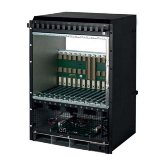
1.7 Shelf Front and Rear View Figure 1: Shelf Front View Cable Tray Hot Swap LED Backplane Fan Tray Fault LED Front Card Cage Fan Tray OK LED Fan Tray ESD Wrist Strap Serial Interfaces for ShMC Slot for PSU... -
Page 9: Esd Wrist Strap Terminals
Figure 2: Shelf Rear View Cable Tray ESD Wrist Strap Terminal Ground Terminal Power Input and Switches 1.8 ESD Wrist Strap Terminals Risk of electrostatic discharge! The Shelf contains static sensitive devices. To prevent static damage you must wear an ESD wrist strap. -
Page 10: Atca Backplane
2 ATCA Backplane The 14‐slot ATCA monolithic Backplane provides: 40 Gb/s connectivity (4 lanes with 10 Gb/s) 12 ATCA Node slots ATCA Hub slots Two dedicated Shelf Manager slots PEM Slots Fan Tray slot ... -
Page 11: Update Channel Interface
2.1.5 Update Channel Interface The Update Channels are wired between two redundant ATCA Backplane slots as 10 differential pairs. The Update Channel is intended to pass information between two redundant ATCA Boards. Figure 3: Update Channels 2.2 Intelligent Platform Management Bus (IPMB) The Shelf uses an Intelligent Platform Management Bus (IPMB) for management communications among all ATCA Boards, the Fan Trays and the Shelf Managers. -
Page 12: Shelf Seeprom
2.3 Shelf SEEPROM The Shelf SEEPROM is a repository of the shelf-specific information, capabilities of the system and other user-configurable options. The SEEPROM contains as example: • a list of which slots are connected together • how the update channels are routed •... -
Page 13: Shelf Manager Cross Connect
2.4 Shelf Manager Cross Connect The ATCA Backplane provides cross connect traces between the Base Hubs and the Shelf Managers. Figure 5: Shelf Manager Cross Connect Table 2: Connector (P23) pin assignments for Shelf Manager Cross Connect Designation Shelf Manager Port Tx1+ Tx1‐... -
Page 14: Logic Ground
2.5 Logic Ground Figure 6: Logic Ground The ATCA Backplane provides a mechanism to connect Logic Ground (GND) and Shelf Ground (Shelf_GND). You can connect/isolate Logic Ground by swapping two screws from position (A) to position (B). • Screws at position (A): Logic Ground and Shelf Ground connected. -
Page 15: Air Filter
3 Air Filter Figure 7: Air Filter 3.1 Introduction The ATCA Shelf provides a replaceable air filter located on top of the fan tray. The filter element is an open cell polyurethane foam special coating to provide improved fire retardation and fungi resistance. -
Page 16: Shelf Ground Connection
4 Shelf Ground Connection ‐ Hazardous voltage! Before powering up the Shelf, make sure that the Shelf Ground terminals are connected to Protective Earth (PE) of the building. The ATCA Shelf provides a Shelf ground terminal at the left rear side. The Shelf ground terminal provides two threads (M6) with a 15.88 mm (5/8“) spacing between... -
Page 17: Fan Tray
5 Fan Tray 5.1 Introduction The Fan Tray is an intelligent FRU controlled by the ShMCs via IPMB. The interchangeable Fan Tray is equipped with 8 high speed / high air flow fans controlled as a group by the IPM Controller in the Fan Tray. -
Page 18: Fan Tray Block Diagram
5.2 Fan Tray Block Diagram Figure 9: Fan Tray Block Diagram ShMC 1 Serial ShMC 2 Serial Air Filter present EXT_PRES 1...4 PSU_PRES 1...4 NSEAT (Short Pin) NTC 1 NTC 2 AVREF 2.5 V 3.3 V GND (Fan Tray present) SDA/SCL_FT local I²C Bus... -
Page 19: Fan Tray Connectors And Indicators
Figure 10: Fan Tray 5.3 Fan Tray Connectors and Indicators The front panel includes a green Fan Tray OK LED, a red Fan Tray Fault LED, and a blue Hot Swap LED. The Hot Swap push button indicates to the Shelf Managers that the Fan Tray is about to be removed. -
Page 20: Fan Control
5.4 Fan Control The Fan Tray‘s on‐board IPM controller has three operation modes: Shelf Manager Mode: The Shelf Manager performs management of the Fan Tray through the two independent bussed IPMB connections. Board Control Mode: The fan tray is controlled by the board in any of the 14 board slots using the PICMG extended IPMI commands. - Page 21 Table 4: DIP Switch Settings Switch No Control Mode Full Speed Full Speed Full Speed Outlet Temperature Curve 2 Outlet Temperature Curve 3 Outlet Temperature Curve 1 Outlet Temperature Curve 1 Intake Temperature curve 2 Intake Temperature curve 3...
-
Page 22: Sensor Table
5.5 Sensor Table Table 5: Sensor Table Type- IPMC Name Type Class Description Code This sensor returns the Fan Tray hot-swap Hot Swap Hot Swap 0xf0 Discrete states. This sensor returns the Shelf FRU hot-swap ShelfFRU HotSwap Hot Swap... - Page 23 Type- IPMC Name Type Class Description Code This sensor indicates the presence of the – FT -48V B1 Fused OEM reserved 0xc0 Discrete 48 V_B branch 1 after fan tray’s main fuse. This sensor indicates the presence of the –...
-
Page 24: Rs-232 Serial Console Interfaces
Type- IPMC Name Type Class Description Code This sensor measures the inlet temperature PSU3 Inlet Temp Temperature 0x01 Threshold of the PSU 3 This sensor measures the output voltage of PSU3 Voltage Out Voltage 0x02 Threshold the PSU 3... -
Page 25: Power
6 Power Hazardous voltage! Before working ensure that the power is removed from the power connection cables. Warning! The Power lines must be protected on site level with 16A breakers or 16A fuses. The Power Supplies are not included with the Shelf. -
Page 26: Power Distribution
6.2 Power Distribution Figure 12: Power Distribution... -
Page 27: Ac Power Supply Units (Psus)
6.3 AC Power Supply Units (PSUs) The AC PSUs with front‐to‐back airflow are hot pluggable from the front side. The Shelf Manager can monitor the PSUs through the IPMC of the fan tray. The fan tray access the PSUs through an I2C bus to CAN bus bride on the Power Distribution Board, since the PSUs only support CAN bus communication. -
Page 28: Power Components
6.4 Power Components Figure 14: Power Input AC Input PSU 4 AC Input PSU 3 AC Input PSU 2 AC Input PSU 1 AC power input is provided by 4 IEC 320‐C20 connectors at the rear side of the Shelf. -
Page 29: Power Branches
6.6 Power Branches Power branches within the Shelf originate from the PEM and powers all the blades, the Shelf Managers and the Fan Trays. The power is divided in four output branches towards the backplane. ‐ ‐ ‐ If the joint power capability of all ATCA boards assigned to a branch is... -
Page 30: Shelf Management
7 Shelf Management The aTCA-81514PA is designed to work with two redundant Shelf Managers in dedicated Shelf Manager slots. Upon request a version with on-blade shelf management is available. With on-blade shelf management, the SEEPROMs on the backplane are connected to the internal I²C bus on the Fan Trays. -
Page 31: Technical Data
8 Technical Data Table 8: Technical Data Physical Dimensions Height Width 482.6 mm Depth (with handles) 470 mm Weight Net Weight 30 kg Gross Weight (including packaging) 65 kg Power AC Input voltage nom. 115V AC / 230V AC... -
Page 32: Dimensions
8.1 Dimensions All dimensions below are in mm. Figure 16: Dimensions 482.6±0.4 465.1±1 663.85 470.04 447.68... -
Page 33: Getting Service
Address: 5215 Hellyer Avenue, #110, San Jose, CA 95138, USA Tel: +1-408-360-0200 Toll Free: +1-800-966-5200 (USA only) Fax: +1-408-360-0222 Email: info@adlinktech.com ADLINK Technology (China) Co., Ltd. Address: 300 Fang Chun Rd., Zhangjiang Hi-Tech Park, Pudong New Area Shanghai, 201203 China 上海市浦东新区张江高科技园区芳春路300号 (201203) Tel: +86-21-5132-8988 Fax: +86-21-5132-3588 Email: market@adlinktech.com...
Need help?
Do you have a question about the aTCA-81514PA and is the answer not in the manual?
Questions and answers