Advertisement
MONTA¯U I EKSPLOATACJI
ZACZEPU KULOWEGO DO
PRZEZNACZENIE
Zaczep kulowy C-257 jest przeznaczony do holowania przyczepy. Zaczep
Œwiadectwo Homologacji uprawniaj¹ce do oznaczenia wyrobu znakiem homologacji E20.
WARUNKI MONTA¯U
Zaczep kulowy
C-257
mo¿e byæ u¿ywany i eksploatowany w samochodzie o w³aœciwym stanie
technicznym elementów nadwozia. Zaczep musi byæ zamontowany i eksploatowany w samochodzie
zgodnie z niniejsz¹ instrukcj¹.
Wszystkie œruby i nakrêtki wystêpuj¹ce w zaczepie kulowym musz¹ byæ dokrêcone odpowiednim
momentem obrotowym (M
) o wartoœciach podanych w poni¿szej tabeli (dla œrub w klasie 8.8):
o
M8
-
25 (Nm)
M10
-
50 (Nm)
WARUNKI EKSPLOATACJI
Zaczep kulowy
C-257
posiada tabliczkê znamionow¹ okreœlaj¹c¹ prawid³owe i bezpieczne obci¹¿enie
zaczepu, tj. :
Typ: C-257
Numer katalogowy zaczepu kulowego
A50-X
Klasa zaczepu kulowego (urz¹dzenia sprzêgaj¹cego)
E20 55R-01 4226
Nr œwiadectwa Homologacji zaczepu kulowego
D =
6,7 kN
Teoretyczna si³a odniesienia dzia³aj¹ca na zaczep kulowy
S =
75 kg
Max. dopuszczalne obci¹¿enie pionowe kuli zaczepu
R = 1200 kg
Max. dopuszczalne obci¹¿enie holowanej przyczepy
D
Si³ê
wylicza siê ze wzoru:
T-technicznie dopuszczalna maksymalna masa, w tonach, pojazdu ci¹gn¹cego
(tak¿e ci¹gników holuj¹cych) ³¹cznie, jeœli wystêpuje, z obci¹¿eniem pionowym
TxR
przyczepy z osiê centraln¹.
D
kN
= g
x
R-technicznie dopuszczalna maksymalna masa, w tonach, przyczepy samochodowej
T+R
z dyszlem ruchomym w p³aszczyŸnie pionowej lub naczepy.
g- przyspieszenie ziemskie (przyjmowane jako 9,81 m/s )
Podczas eksploatacji poszczególne elementy zaczepu kulowego powinny byæ utrzymane w nale¿ytym
stanie technicznym i zabezpieczone przed dzia³aniem korozji. W czasie holowania przyczepa musi byæ
z³¹czona dodatkowym elastycznym z³¹czem o odpowiedniej wytrzyma³oœci (linka, ³añcuch). W czasie
eksploatacji zaczepu kulowego nale¿y okresowo sprawdzaæ po³¹czenia œrubowe, a w przypadku
poluzowania nakrêtek nale¿y je dokrêciæ.
MONTA¯
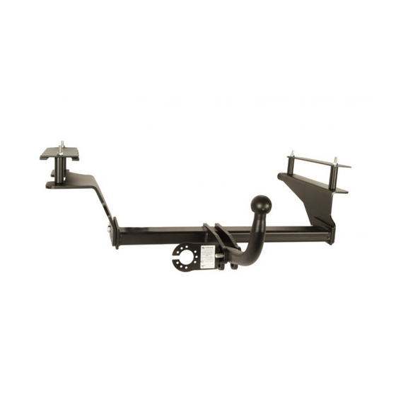
Zaczep kulowy
C-257
sk³ada siê z nastêpuj¹cych elementów:
1. Korpus
- 1 szt.
2. Kula
- 1 szt.
- 1 szt.
3. Uchwyt gniazda elektrycznego
- 1 szt.
4. Wspornik prawy
5. Wspornik lewy
- 1 szt.
- 1 szt.
6. Wzmocnienie prawe
- 1 szt.
7. Wzmocnienie lewe
8. Tulejka Ø25/Ø15x69
- 1 szt.
- 2 szt.
9. Tulejka Ø25/Ø15x77
- 1 szt.
10. Tulejka Ø25/Ø15x79
W celu
zamontowania zaczepu kulowego nale¿y przestrzegaæ poni¿szego opisu:
1. Monta¿ zaczepu nie wymaga demonta¿u zderzaka tylnego samochodu wymaga natomiast jego podciêcia.
30.10.2015.
FITTING AND OPERATION MANUAL
DESTINATION
Tow bar C-257 is designed for towing a trailer. This ball hook has a current certification of approval
authorizing the product with E20 certification sign.
FITTING CONDITIONS
Tow bar C-257 can be used and operated in a car with proper technical conditions of body elements.
Those parts cannot be mechanically damaged . The ball hook has to be installed and operated in a car
according to this instruction . All bolts and nuts in ball hook have to be screwed down with proper torque
(M
) . Torque values are given below :
o
M8
-
25 (Nm)
M10
-
50 (Nm)
OPERATION CONDITIONS
The tow bar C-257 has a rating plate describing correct and safe loads of the hook :
Tow bar catalogue number.
Typ: C-257
Tow bar class ( compressing device )
A50-X
Tow bar certification of approval number
E20 55R-01 4226
Teoretical related force working on a ball hook
D =
6,7 kN
Max permissible vertical load of the hook ball
S =
75 kg
Max permissible load of towing trailer
R = 1200 kg
D - force is calculated using the following formula:
T-technically permissible maximum mass in tonnes of the towing vehicale (also
towning tractors) including, if neccessary, the vertical load of a centrale axle trailer.
TxR
D
kN
R-technically permissible maximum mass in tonnes of the full trailer with drawgal free
= g
x
T+R
to move in the vertical plane or of the semi-trailer.
g-acceleration due to gravity(assumed as 9,81 m/s )
During operating individual elements of ball hook should be kept in a proper technical condition and
protected from corrosion . The trailer must be linked with an elastic joint with proper durability ( cord ,
chain ) while towing .It is necessary to check periodically bolt joints during ope rating the ball hook. If
screws are eased , it is necessary to screw them down .
FITTING
The tow bar C-257 is made up of the following elements :
1. Towbar mainframe
- 1 piece
2. Tow ball
- 1 piece
3. Electrical socket
- 1 piece
4. Right support
- 1 piece
5. Left support
- 1 piece
- 1 piece
6. Right strengthening
7. Left strengthening
- 1 piece
8. Sleeve Ø25/Ø15x69
- 1 piece
- 2 pieces
9. Sleeve Ø25/Ø15x77
- 1 piece
10. Sleeve Ø25/Ø15x79
Please follow the installation fitting instruction below in order to ensure correct installation of the towbar:
30.10.2015.
INSTRUKCJA
SAMOCHODU
Chevrolet Aveo (4D)
(2006 - 2011
)
Nr kat. C-257
ten posiada aktualne
M12
-
85 (Nm)
M16
-
200 (Nm)
2
11.
Œruba M10x120
(PN/M-82101)
- 4 szt.
12.
Œruba M12x35
(PN/M-82105)
- 4 szt.
13.
Œruba M12x70
(PN/M-82101)
- 2 szt.
14. Podk³adka sprê¿ysta Ø10,2
- 4 szt.
15. Podk³adka sprê¿ysta Ø12,2
- 6 szt.
16. Podk³adka okr¹g³a Ø10,5
- 4 szt.
17. Podk³adka okr¹g³a Ø13,0
- 6 szt.
- 4 szt.
18. Nakrêtka M10
19. Nakrêtka M12
- 4 szt.
Nr kat. C-257
TOW BAR FOR
Chevrolet Aveo (4D)
(2006 - 2011)
Cat. No.C-257
M12
-
85 (Nm)
M16
-
200 (Nm)
2
11. Bolt
M10x120
- 4 pieces
12. Bolt
M12x35
- 4 pieces
13. Bolt
M12x70
- 2 pieces
14. Spring washer Ø10,2
- 4 pieces
- 6 pieces
15. Spring washer Ø12,2
- 4 pieces
16. Round washer Ø10,5
- 6 pieces
17. Round washer Ø13,0
- 4 pieces
18. Nut M10
- 4 pieces
19. Nut M12
Cat. No. C-257
2. Opró¿niæ pod³ogê baga¿nika (zdemontowaæ w baga¿niku tylne panele oraz poluzowaæ boczne panele).
3. Od do³u samochodu odkrêciæ filtr.
4. Zdemontowaæ uchwyt holowniczy (nie bêdzie ponownie montowany).
5. Wykonaæ podciêcie w œrodkowej czêœci zderzaka od spodu (~55x45mm).
:
6. Wywierciæ otwór
Ø
11 w pod³odze baga¿nika w punkcie A prowadz¹c wiert³o poprzez otwór od spodu
pod³u¿nicy.
7. Umieœciæ w baga¿niku wzmocnienie lewe (7) na otworze A i wywierciæ otwór 11 w punkcie B (rys.1).
8. Umieœciæ w baga¿niku wzmocnienie prawe (6) i wywierciæ otwory 11 w punktach (C, D) (rys.2).
9. Powiêkszyæ otwory (A, B, C, D) tylko od strony baga¿nika do 30.
10. Zdj¹æ naddatki masy t³umi¹cej w miejscu styku z elementami zaczepu.
11. Od strony baga¿nika w otwory A, B, C, D wsun¹æ tulejki dystansowe (8, 9, 10) wed³ug schematu, przy³o¿yæ
wzmocnienia (6, 7) wraz z trzema œrubami M10x120 (11).
12. Od spodu prawej pod³u¿nicy przy³o¿yæ wspornik prawy(4) i skrêciæ w punkcie C œrub¹ M10x120 (11) wraz
z podk³adk¹ okr¹g³¹ 10,5 (16), sprê¿yst¹ 10,2 (14) i nakrêtk¹ M10 (18) oraz skrêciæ w punkcie D œrub¹
Ø
M10x120 (11) wraz z podk³adk¹ okr¹g³¹ 10,5 (16), sprê¿yst¹ 10,2 (14) i nakrêtk¹ M10 (18).
13. Od spodu lewej pod³u¿nicy przy³o¿yæ wspornik lewy (5) i skrêciæ œrubami M10x120 (11) wraz z podk³adkami
okr¹g³ymi 10,5 (16), sprê¿ystymi 10,2 (14) i nakrêtkami M10 (18).
Ø
14. Pomiêdzy wsporniki (4, 5) wsun¹æ korpus (1) i skrêciæ œrubami M12x35 (12) wraz z podk³adkami okr¹g³ymi
Ø
13,0 (17), sprê¿ystymi 12,2 (15) i nakrêtkami M12 (19).
15. Do korpusu (1) dokrêciæ kulê (2) i uchwyt gniazda elektrycznego (3) œrubami M12x70 (13) wraz
z podk³adkami okr¹g³ymi 13,0 (17), sprê¿ystymi 12,2 (15) i nakrêtkami M12 (19).
16. Dokrêciæ filtr i zamontowaæ ponownie to co zosta³o usuniête z baga¿nika.
Przestrzeganie niniejszej instrukcji zapewnia prawid³owy monta¿ i eksploatacjê
Po zamontowaniu zaczepu kulowego C-257 nale¿y uzyskaæ wpis w dowodzie rejestracyjnym pojazdu.
UWAGA:
Sprawdzaæ po³¹czenia œrubowe po przejechaniu 1000 km. Kulê zawsze utrzymywaæ w czystoœci i
smarowaæ smarem sta³ym. Stosowaæ os³onê kuli.
257 wykluczaj¹ dalsz¹ jego eksploatacjê. Uszkodzony zaczep nie mo¿e byæ naprawiany. W przypadku nie
przestrzegania opisanego sposobu monta¿u lub niew³aœciwego jego u¿ytkowania producent nie ponosi
odpowiedzialnoœci za powsta³e szkody.
SCHEMAT MONTA¯U:
Rys.1
Rys.2
UWAGA:
Cena zaczepu kulowego nie obejmuje wi¹zki elektrycznej.
1. Installation does not require removal of the rear bumper of the car while require its cutting.
2. Empty the trunk floor ( remove the back panels and loosen the side panels).
3. From the bottom of the car, unscrew the filter.
4. Remove the towing handle ( it will not be reused).
5. Make an undercut from the bottom in the middle part of the bumper (~55x45mm).
6. Drill the holes 11 in the trunk floor in point A through the of in the bottom of the stringer.
Ø
7. Place in the trunk the left strengthening (7) on the hole A and drill the hole 11 point B (fig. 1).
8. Place in the trunk the right strengthening (6) and drill the holes 11 in points C, D (fig. 2).
9. Enlarge the holes (A, B, C, D) just from the side of the trunk to 30.
10. Remove the allowances of the damping mass in contact place with elements of towbar.
11. From the side of the trunk slide the sleeves (8, 9, 10) according to the schema into the holes A, B, C, D,
attach the strengthening (6, 7) with three bolts M10x120 (11).
12. Attach the right support (4) to the bottom of the sides of the stringers and screw in point C using bolts
M10x120 (11) with round washers 10,5 (16), spring washer 10,2 (14) and nuts M10 (18). Screw in point
D using bolt M10x120 (11) with round washers 10,5 (16), spring washer
13. Attach the left support (5) to the bottom side of the left stringers and screw using bolts M10x120 (11) with
round washers 10,5 (16), spring washers 10,2 (14) and nuts M10 (18).
Ø
14. Between supports (4, 5) slide the towbar mainframe (1) and screw using bolts M12x35 (12), with round
washers 13,0 (17), spring washers 12,2 (15) and nuts M12 (19).
Ø
15. Tighten the tow ball (2) and electrical plate (3) to the towbar mainframe (1) using bolts M12x70 (13) with
round washers 13,0 (17), spring washers 12,2 (15) and nuts M12 (19).
Ø
16. Screw on the filter and install all removed elements.
Obeying this instruction assures correct montage and the C-257 tow bar
After assembling of the tow bar C-257 you have to get entry in cars registration book.
CAUTION :
Check if all bolts and nuts are correctly tightened after 1000km. Keep tow ball clean, grease and cased.
All mechanical damages of tow bar excludes its further exploitation . Damaged ball hook cannot be
repaired. In case of braking the rules of montage or unproper usage manufacturer do not take
responsibility for arised damages .
MONTAGE DIAGRAM :
Fig.1
Fig.1.
Fig.2
NOTE :
Bunch of wires is not included (in total price).
Ø
Ø
Ø
Ø
Ø
Ø
Ø
Ø
Ø
zaczepu kulowego C-257.
Wszystkie uszkodzenia mechaniczne zaczepu kulowego C-
18
14
16
11
18
B
14
16
11
7
A
9
10
1
5
12
3
17
12
15
15
19
17
Ø
Ø
Ø
Ø
Ø
Ø
Ø1
Ø
Ø
Ø
operating.
18
14
16
11
18
14
B
16
11
7
A
9
10
1
5
12
3
17
12
15
15
17
19
Ø
D
11
16
6
14
18
8
C
4
9
19
15
17
12
11
16
14
12
18
15
17
13
17
2
15
19
Nr kat. C-257
0,2 (14) and nuts M10 (18).
D
11
16
6
14
18
8
C
4
9
19
15
17
12
11
16
14
12
18
15
17
13
17
15
2
19
Cat. No. C-257
Advertisement
Table of Contents

Related Manuals for Steinhof C-257


Summary of Contents for Steinhof C-257
- Page 1 (6, 7) with three bolts M10x120 (11). Tow bar C-257 is designed for towing a trailer. This ball hook has a current certification of approval 12. Attach the right support (4) to the bottom of the sides of the stringers and screw in point C using bolts authorizing the product with E20 certification sign.
- Page 2 Rundunterlegscheiben Ø10,5 (16), den Federringen Ø10,2 (14) und den Muttern M10 (18) anschrauben. Die Anhängerkupplung C-257 darf nur an Fahrzeugen montiert und genutzt werden, deren Karosserie in 14. Zwischen die montierten Stützen (4, 5) das Gestell (1) einschieben und mit den Schrauben M12x35 (12), den einem einwandfreien technischen Zustand ist.
Need help?
Do you have a question about the C-257 and is the answer not in the manual?
Questions and answers