Table of Contents
Advertisement
Quick Links
Operation and Service Guide
Agilent Technologies
8648A/B/C/D Signal Generator
Serial Number Prefixes:
This manual applies directly to the following model/serial prefix
combinations and below.
8648A
8648B
8648C
8648D
3847A/U
4037A/U
4037A/U
4037A/U
Part Number 08648-90048
Printed in USA
March 2001
Supersedes September 2000
© Copyright 1996, 1998-2001 Agilent Technologies, Inc.
.
Advertisement
Table of Contents

Related Manuals for Agilent Technologies 8648A


Summary of Contents for Agilent Technologies 8648A
- Page 1 Serial Number Prefixes: This manual applies directly to the following model/serial prefix combinations and below. 8648A 8648B 8648C 8648D 3847A/U 4037A/U 4037A/U 4037A/U Part Number 08648-90048 Printed in USA March 2001 Supersedes September 2000 © Copyright 1996, 1998-2001 Agilent Technologies, Inc.
- Page 2 WEEE Directive This product complies with the WEEE Directive (2002/96/EC) marking requirements. The affixed label indicates that you must not discard this electrical/electronic product in domestic household waste. Product Category: With reference to the equipment types in the WEEE Directive Annex 1, this product is classed as a “Monitoring and Control instrumentation”...
-
Page 3: Table Of Contents
Contents 1. Operation Quick Overview .............1-2 1. - Page 4 Contents 1b. Operation Reference Frequency and Amplitude........... . 1b-2 1.
- Page 5 Contents GPIB Status Reporing ............2-12 External Modulation Input Level Status.
- Page 6 5.Service Shipping Your Instrument Back to Agilent Technologies ......5-2 Recommended Test Equipment ..........5-3 Post-Repair.
- Page 7 Motherboard Audio Path (All 8648A/B/C/D) ........7-24...
- Page 8 Contents Connect the Test Equipment ..........8-7 Configure the Measuring Receiver .
- Page 9 Contents Configure the 8648 ............8-19 Measure Distortion Amplitudes .
- Page 10 8648A Test Record ........
- Page 11 Contents 8648D Test Record ............8-122 9.
- Page 12 Contents xviii...
-
Page 13: Operation
Operation “Operation” contains the following information: • 1. Operation: Provides a quick overview of the instrument’s operation. • 1a. Operation Examples: provides examples to help you learn how to operate the instrument. • 1b. Operation reference: Provides quick access to information about each of the instrument’s functions. -
Page 14: Quick Overview
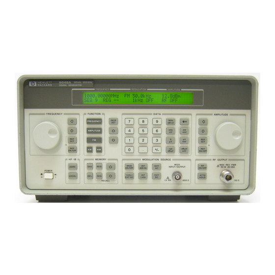
Operation Quick Overview Quick Overview Figure 1-1. The 8648 Signal Generator 1. Power Key Press to power up the instrument. The instrument powers up to the same state it POWER was in when power was turned off, except that the RF output will be turned off and the digit-select arrow keys (⇐... -
Page 15: Function And Data Keys
Quick Overview The following table describes the prefixes that apply to the various 8648 models equipped with an LCD. A. Liquid Crystal Display (LCD) (labels located above the display) 8648A Prefix 8648B Prefix 8648C Prefix 8648D Prefix 3636A and below... -
Page 16: Increment Set Keys
Operation Quick Overview 4. Increment Set Keys When you press a FUNCTION key, that function becomes the active function. Press INCR SET to view or change the increment value for the active function. Press ⇑ or ⇓ at any time to change the active function setting by the increment value. -
Page 17: Modulation Source
Operation Quick Overview 7. Modulation Source Press to turn on or off the modulation source. Press MOD ON/OFF INT 400 kHz INT 1 kHz select one of the internal source tones for modulating the RF output signal. These tones are also available as an output signal at the MOD INPUT/OUTPUT port when they are selected. - Page 18 Operation Quick Overview...
-
Page 19: 1A. Operation Examples
Operation Examples This section contains operating examples to help you learn how to operate the signal generator. These examples can be performed without any additional equipment. The pager testing example can only be performed if Option 1EP is present. If this is the first time you have operated this instrument, perform each of the following examples for a quick introduction to general operation. - Page 20 Operation Examples 1a-2...
-
Page 21: Setting The Rf Output Signal
Operation Examples Setting the RF Output Signal Setting the RF Output Signal In this example, you will set the frequency, amplitude, and modulation level of the RF output signal. Setting the Frequency 1. Set the frequency to 100 MHz using the keys shown below the instrument diagram. If you make a mistake while entering a value, press ⇐... -
Page 22: Setting The Modulation
Operation Examples Setting the RF Output Signal Setting the Modulation 4. Set the FM deviation to 3 kHz. The modulation rate is displayed below the deviation setting. Use the MODULATION SOURCE keys to select a modulation source and turn modulation on or off. 1a-4... -
Page 23: Incrementing Or Decrementing The Rf Output Signal
Operation Examples Incrementing or Decrementing the RF output Signal Incrementing or Decrementing the RF output Signal In this example, you will increment the amplitude and frequency of the RF output signal. Preliminary Steps 1. If they are not already set, set the frequency to 100 MHz and the amplitude to −100 dBm. - Page 24 Operation Examples Incrementing or Decrementing the RF output Signal 4. Increment the Rf output frequency in 25 kHz steps. The increment keys affect the last FUNCTION selected (FREQUENCY, AMPLITUDE, FM, AM, OR φM). 1a-6...
-
Page 25: Using The Memory Registers
Operation Examples Using the Memory Registers Using the Memory Registers The memory register examples show you how to crate a sequence of registers, delete a register from that sequence, renumber the registers in the sequence, and insert a new register in the sequence. Up to 10 register sequences can be defined (0 through 9). -
Page 26: Saving Instrument Setting In Register Sequences
Operation Examples Using the Memory Registers Saving Instrument Setting in Register Sequences In this ten step example, you will use the memory keys to create a sequence containing three registers. Each register will contain a different frequency setting. Selecting the Sequence 1. - Page 27 Operation Examples Using the Memory Registers 4. Set the frequency setting to 11 MHz. 5. Save the instrument settings in register 01. 6. Set the frequency to 12 MHz. 7. Save the instrument settings in register 02. 1a-9...
- Page 28 Operation Examples Using the Memory Registers Checking the Sequence 8. Recall the registers in sequence 0. The ⇑ and ⇓ keys recall registers or sequences depending on which key was pressed last Checking a Different Sequence 9. Select sequence 1. 10.Step through the registers in sequence 1 if there are registers saved in it.
-
Page 29: Deleting A Register From The Sequence
Operation Examples Using the Memory Registers Deleting a Register from the Sequence In this example, you will delete a register from the sequence you created in the preceding example. Selecting the Sequence 1. Select sequence 0. Deleting a Register 2. Delete register 01 from sequence 0. NOTE The contents of the register are recalled when it is deleted. -
Page 30: Renumbering The Registers In A Sequence
Operation Examples Using the Memory Registers 3. Step through the remaining registers in sequence 0. The deleted register number has been removed from the sequence. Note that the instrument does not renumber the registers when one is deleted. Renumbering the Registers in a Sequence In this example, you will eliminate the skip from register 00 to register 02 in sequence 0 caused when you deleted register 01 in the previous example. -
Page 31: Inserting A Register In A Sequence
Operation Examples Using the Memory Registers Checking the Sequence 3. Step through the register sequence. NOTE In this example, you renumbered one register. when you need to renumber two or more registers, use instead of to recall each register until you get to the last register in the sequence, then use Inserting a Register in a Sequence In this example, you will insert a register into the sequence you created in the previous... - Page 32 Operation Examples Using the Memory Registers 3. Recall register 00. Register 01 can now be used to save the settings that are saved in register 00. 4. Save the recalled settings into register 01. Register 00 can now be used to save the new settings. Saving a New Register 5.
- Page 33 Operation Examples Using the Memory Registers 6. Save the settings in register 00. Press ⇑ to check the new sequence. 1a-15...
-
Page 34: Offsetting The Rf Output From A Reference
Operation Examples Offsetting the RF Output from a Reference Offsetting the RF Output from a Reference In this example, you will enter an RF output frequency, set it as the reference value, and then offset the RF output frequency 10 MHz below the reference value. Setting the Reference Value 1. -
Page 35: Offsetting The Rf Output
Operation Examples Offsetting the RF Output from a Reference Offsetting the RF Output 3. Offset the output frequency 10 MHz below the reference frequency. You can enter in the offset value directly, or use the knob or ⇑ and ⇓ keys. In the reference mode, the output frequency equals the reference frequency ±... - Page 36 Operation Examples Offsetting the RF Output from a Reference 6. Change the displayed units to kHz. Note that for amplitude, reference settings are displayed in dB units only. Setting a New Reference Value 7. Set the current output frequency as the new reference frequency at any time. 1a-18...
-
Page 37: Holding The Output Attenuator Range
Operation Examples Holding the Output Attenuator Range Holding the Output Attenuator Range In this example, you will hold the output attenuator so it does not change ranges when you change the amplitude setting. This will prevent attenuator range changes from affecting the output signal. -
Page 38: Adjusting The Amplitude
Operation Examples Holding the Output Attenuator Range Adjusting the Amplitude 3. Adjust the amplitude setting. Now amplitude changes do not cause the attenuator to change its range setting. Consequently, amplitude changes are limited to the range provided by the instrument’s vernier. -
Page 39: Setting A User Selectable Modulated Frequency And Waveform (Option 1E2 Or 1Ep Only)
Operation Examples Setting a User Selectable Modulated Frequency and Waveform (Option 1E2 or 1EP Only) Setting a User Selectable Modulated Frequency and Waveform (Option 1E2 or 1EP Only) This modulation example can only be performed if Option 1E2 or 1EP is NOTE present. -
Page 40: Setting The Modulated Frequency
Operation Examples Setting a User Selectable Modulated Frequency and Waveform (Option 1E2 or 1EP Only) Setting the Modulated Frequency 3. Set the modulated frequency to 1.5 kHz. key is the only accepted units key. 1a-22... -
Page 41: Signaling A Numeric-Type Flex Pager (Option 1Ep Only)
Therefore, these keys have multiple functions on instruments with Option 1EP. Figure 1a-1. The 8648A Option 1EP Signal Generator Setting Up Pager Encoding The following steps are required to set up pager encoding on the signal generator. Details of setting each parameter are provided following this overview. -
Page 42: Entering Pager Encoding Settings
Operation Examples Signaling a Numeric-Type FLEX Pager (Option 1EP Only) Use the ⇓ (NEXT) and ⇑ (PREV) keys to scroll through the encoder parameters. The cursor will blink around the first letter of the active parameter. The ⇓ (NEXT) key moves forward sequentially through each pager encoder parameter and the ⇑... -
Page 43: Selecting The Data Rate And Pager Type Settings
Operation Examples Signaling a Numeric-Type FLEX Pager (Option 1EP Only) Selecting the Data Rate and Pager Type Settings 3. Set DATA RATE to 3200/2 and PAGER TYPE to NUMERIC, using the AMPLITUDE/ENCODER knob and the ⇓ (NEXT) key. You may choose to set the data rate to one of the other settings; you FLEX pager should automatically adjust. -
Page 44: Selecting The Message Settings
Operation Examples Signaling a Numeric-Type FLEX Pager (Option 1EP Only) Selecting the Message Settings 5. You may choose one of the five fixed messages (only numbers one and five are useful for numeric pagers) or you may define your own message. For this example, use your own phone number as the user-defined message: a. -
Page 45: Selecting The Pager Capcode (Address)
Operation Examples Signaling a Numeric-Type FLEX Pager (Option 1EP Only) 7. Set IMMEDIATE STOP to OFF, HEADER to ON, and TERMINATOR to ON using AMPLITUDE/ENCODER knob and the key. These are default settings that normally would not be adjusted. Press the ⇓ (NEXT) key to move to the next page. Selecting the Pager Capcode (Address) 8. -
Page 46: Selecting The Protocol Settings
Operation Examples Signaling a Numeric-Type FLEX Pager (Option 1EP Only) 9. ADDRESS TYPE and ADDRESS1 are set automatically when the capcode is entered in the previous menu. If A0012477 was entered, SHORT and 0045245 would be displayed respectively. Generally, you would not change these settings. Press the ⇓... -
Page 47: Selecting The Roaming Mode Settings
Operation Examples Signaling a Numeric-Type FLEX Pager (Option 1EP Only) Selecting the Roaming Mode Settings 11.Set ROAMING MODE to NONE using the AMPLITUDE/ENCODER knob. Press the ⇓ (NEXT) key to move to the next page. Encoding 12.To start encoding after selecting all pager encoder parameters, press the INCR SET (START/STOP) key. - Page 48 Operation Examples Signaling a Numeric-Type FLEX Pager (Option 1EP Only) 1a-30...
-
Page 49: 1B. Operation Reference
Operation Reference This chapter describes each of the instrument’s functions including all of the front panel keys, the rear panel connectors, and the optional remote interface and memory interface. This information is presented in the same functional groups as the front panel key functional groupings. -
Page 50: Frequency And Amplitude
Operation Reference Frequency and Amplitude Frequency and Amplitude The knob and reference set keys work similarly for both frequency and amplitude settings. 1. Knob Turn the knobs to increment or decrement the frequency and amplitude settings. The knobs are always active when the instrument is in local operation. If Option 1EP is present and the signal generator is in the ENCODER mode, the knob in the AMPLITUDE/ENCODER block is used to select the desired setting for each pager encoder parameter. -
Page 51: Ref On/Off
Operation Reference Frequency and Amplitude The RF output signal is not changed when you press this key. Units When you press for frequency, values can be entered in MHz or kHz. For REF SET amplitude, values can be entered in any of the amplitude units provided, but they are displayed in dB only. -
Page 52: Function
RF output. However, the power does blank for a few milliseconds when crossing the frequencies at 249, 501, 1001, 1260, 1600, 2001, 2520, and 3200 MHz. Model Frequency Range 8648A 100 kHz to 1000 MHz 8648B 9 kHz to 2000 MHz 8648C... -
Page 53: Amplitude
30 ms. Output Amplitude Ranges Model Frequency Range Amplitude +10 to −136 dBm 8648A 100 kHz to 1000 MHz ≥ 2500 MHz +13 to −136 dBm 8648B/C/D +10 to −136 dBm >... -
Page 54: Setting Up The Pager Encoder
Therefore, these keys have multiple functions on instruments with Option 1EP. Figure 1b-1. 8648A Option 1EP Signal Generator For numeric messages, the following keys are assigned for the special characters in addition to the standard numeric keys (0 to 9). - Page 55 Operation Reference Function 1. ENCODER Before selecting the pager encoder mode, check that the correct pager carrier NOTE frequency and FM deviation have been set. To select the pager encoder mode, press (ENCODER) twice: once to set FM deviation, then again to toggle between the standard functions and the pager encoder mode. The display will look like the following: This format menu is always displayed first when the pager encoder mode is selected.
- Page 56 FLEX: FLEX-TD format FLEX-TD: POCSAG format POCSAG: Pseudorandom Sequence (PN15) PN15: Re-synchronization function (for FLEX/FLEX-TD pagers only) RESYNC: Servicing the 8648A Option 1EP SERVICE: • POLARITY selects the data polarity. Normal polarity Normal: POCSAG FLEX/FLEX-TD FLEX/FLEX-TD (2-Level FSK), (4-Level FSK) RESYNC, PN15 “1”: Carrier −...
- Page 57 Operation Reference Function FLEX/FLEX-TD Setting the data Rate and Pager Type The parameter menu for the data rate and the pager type looks like the following: • DATA RATE specifies how fast the data stream is output in bits per second and whether it is 2-level or 4-level FSK.
- Page 58 Operation Reference Function If NUMBERED is selected, the next parameter to be selected is NUMBER as follows. NUMBER is for setting the initial number of the numbered numeric message that will be transmitted. The allowable range is 0 to 63. If HEX/BIN is selected, the next setting to be selected is BLOCKING LENGTH: •...
- Page 59 Operation Reference Function • MESSAGE NO. is defined as the following where “X” represents the phase setting: Arbitrary message set from the external controller using the GPIB capability. The data must be entered in units of works. Refer to ‘[SOURce]:PAGing[:FORMat]:{POCSag|FLEX|FTD}:ARBitrary: DEFine <NR1>, <NR2>,..., <NR1>”...
- Page 60 Operation Reference Function Setting the Encoding Mode The number of times a message is transmitted and the level of that transmission are determined by the following menu: • MODE determines whether the message will be output once or multiple times when INCR SET (START/STOP) is pressed.
- Page 61 Operation Reference Function • TERMINATOR sets whether the re-synchronization pattern is output after the last message. The collapse cycle will determine in which frame the re-synchronization pattern appears after the (START/STOP) key is pressed to stop or at the end of a burst sequence (refer to INCR SET “FLEX/FLEX-TD Signaling Examples”).
- Page 62 Operation Reference Function • DUMMY CALL inserts a message with all 5s in all non-call phases. This is required by the FLEX-TD standard (RCR STD-34A) for sensitivity testing. Default setting. Activates the dummy call function for equalizing the FSK deviation. An address for the non-call phases must be set. Does not activate the dummy call function.
- Page 63 Operation Reference Function Setting the Protocol The protocol menu displays the following information when “A0000001” is the previously entered capcode. These parameters, except for CYCLE, are all automatically set when the capcode is entered in the PAGER CODE data field. •...
- Page 64 Operation Reference Function Tests a pager in the SSID and NID modes. The NID mode, in addition to the SSID, NID: SSID mode, is a roaming network for covering wider multiple areas. NID consists of a network address and a short message vector as follows: —...
- Page 65 Operation Reference Function After completing the previous menu, set FRAME OFFSET in the following menu: • FRAME OFFSET: Defines the number of frames to be offset by BIW101 from the signaling frame at the home area. The allowable range is 0 to 63. The next menu is displayed for setting the NID mode after completing the SSID mode settings only if the SSID and NID modes are selected.
- Page 66 Operation Reference Function NOTE REPEAT is displayed additionally only if FLEX-TD is selected in the format menu. If MESSAGE NO. is set to 0, the display is changed as follows: NOTE If the RF output is turned off, AMPLITUDE x.xdBm will be substituted for RF OFF. While encoding, the blinking cursor is on the first character A of AMPLITUDE or R of RF OFF.
- Page 67 Operation Reference Function — With TERMINATOR set to ON, the asynchronous state signal is output in the frame where the next message was supposed to occur (as determined by the collapse cycle). Cycle Frame CC = 1 idle message idle message idle message...
- Page 68 Operation Reference Function • Roaming Mode: SSID, NID Field Phase A Phase B, C Phase D Word 0 of Block Info Dummy Block Info Dummy Block Info block 0 Word 1 of BIW000 BIW101 BIW101 block 0 Word 2 of BIW111 BIW101 BIW101...
- Page 69 Operation Reference Function NOTE If the firmware revision of the 8648A option 1EP is B.04.08 or below, the contents in each phase are shown in the following table: • 6400 bps, 4-level FSK • Call in Phase: A • Address Type: Long Address •...
- Page 70 Operation Reference Function where, BI: Block Information AF: Address Field VF: Vector Field MF: Message Field IB: Idle Block POCSAG Setting the Data Rate and Pager Type The parameter menu for the data rate and the pager type looks like the following: •...
- Page 71 Operation Reference Function For ALPHANUM 8BIT First Byte Second Byte Bit number Bit streams Characters For ALPHANUM 7BIT The eighth bit (b8) is ignored as follows: First Byte Second Byte Bit number Bit streams Characters When converting the binary data stream to 2-level FSK, the first bit out becomes the least significant bit (LSB) of the 2-level symbol with the following bit the most significant bit (MSB) of the symbol.
- Page 72 Operation Reference Function START BATCH and STOP BATCH in the following menu: The allowable ranges for both are 000 to127. Displays: 0123456[-] Displays: ABCDEFG[P] Displays: TEST PAGING: POCSSAG Displays: ALPHANUMERIC 40CHARS TEST PAGING: POCSAG Displays: 8888888888888888888888888888888888888888 for LCD test with 40 characters of “8”. User-definable message, up to 40 characters long, set from the front panel.
- Page 73 Operation Reference Function • MODE determines whether the message will be output once or multiple times when INCR SET (START/STOP) is pressed. Outputs the message once. SINGLE: Outputs the message the number of times specified in the BURSTS field (3 BURST: times in this example).
- Page 74 Operation Reference Function RESYNC Setting the Encoding Mode The following parameters must be set to activate the resynchronization function for a FLEX/FLEX-TD pager under test: • BURSTS defines the number of data to make a pager resynchronized with this pager encoding signal.
- Page 75 While encoding, the blinking cursor is on the first character A of AMPLITUDE or R of RF OFF. SERVICE This function is used for servicing the 8648a Option 1EP, and provides a continuous FSK signal. Setting the Data Rate The following parameter must be set to activate the service function:...
- Page 76 Operation Reference Function • CALIBRATION FSK is one of the data rates as follows: 512 bps, 2-level FSK 512/2: 1200 bps, 2-level FSK 1200/2: 1600 bps, 2-level FSK 1600/2: 2400 bps, 2-level FSK 2400/2: 3200 bps, 2-level FSK 3200/2: 3200 bps, 4-level FSK 3200/4: 6400 bps, 4-level FSK 6400/4:...
-
Page 77: Pulse Modulation
Operation Reference Function Pulse Modulation NOTE Pulse modulation is valid only for instruments with Option 1E6. 1. PULSE To select pulse modulation, press (PULSE) twice. If RF is on, the display will look like the following representation. The key enables or disables the pulse MOD ON/OFF modulator. - Page 78 Operation Reference Function The following keys are invalid when the pulse modulation screen is visible: • INT 400 Hz • INT 1kHz • EXT AC • EXT DC • 1kHz+EXT DC 1b-30...
-
Page 79: Increment Set
Increment Set Ranges Function Range Frequency 1 Hz to 999.75 MHz Amplitude > 0.0 to 149.0 dB (8648A) Amplitude > 0.0 to 150.5 dB (8648B/C/D) FM Deviation > 0.0 to 100 kHz AM Depth > 0.0 to 100% ΦM Deviation >... -
Page 80: Data
Operation Reference Function Data 1. MHz/dBm, kHz/mV, %/µV, rad/dBµV Press a units key after you enter a value. This terminates the entry. Note that the units keys in the left column are each labeled with an amplitude unit on the bottom and a frequency or modulation unit on the top. - Page 81 Operation Reference Function 3. emf Press these keys to display the amplitude value indicated on the key label in electromotive force units. Emf is the RF output voltage with no load. It is twice the output voltage with a 50 ohm load. 4.
-
Page 82: Instrument Preset
Operation Reference Function Instrument Preset ⇐ POWER Turn the instrument on while pressing the backspace key (⇐)to perform an instrument preset. The instrument will power up to factory-defined settings shown in the following table. Save and recall registers are not affected by this operation. POWER DEL Turn the instrument on while pressing the memory key to perform a clear memory. - Page 83 Operation Reference Function Instrument Preset Settings Function Parameter Setting RF Frequency Frequency 100 MHz Increment 10 MHz Reference 0.0 MHz −136 dBm RF Amplitude Power Level Increment 1.0 dBm Reference 0.0 dBm Input Internal Frequency 1 kHz Coupling State Deviation Increment 0.1 kHz Input...
- Page 84 Operation Reference Function Instrument Preset Settings Function Parameter Setting Pager Encoding (Option 1EP) FORMAT FLEX POLARITY NORMAL FILTER DATA RATE 1600/2 (for FLEX/FLEX-TD) 512 (for POCSAG) PAGER TYPE NUMERIC VECTOR TYPE STANDARD BLOCKING LENGTH 1BIT FUNCTION MESSAGE NO. MESSAGE LENGTH MODE SINGLE BURSTS...
- Page 85 Operation Reference Function Instrument Preset Settings Function Parameter Setting Modulation FREQUENCY 1.00 kHz Generator SHAPE SINE (Option 1E2) 1b-37...
-
Page 86: Gpib
Operation Reference Function GPIB 1. ADRS Press to view the instrument’s GPIB address setting in the second line of the ADRS FREQUENCY display. To change the address, press and a two-digit number. For example, enter 01 to set ADRS the address to 1. Acceptable HP-IB addresses are 00 through 30. -
Page 87: Memory
Operation Reference Function Memory The memory keys allow you to save instrument settings into memory registers and recall the registers in a numeric sequence. Up to 10 register sequences can be defined (0 through 9). A sequence can contain up to 100 registers (00 through 99). - Page 88 Operation Reference Function 1. SAV Press and a register number (00 through 99) to save the current operating settings in a memory register. All front-panel settings except the knob digit positions and the GPIB address will be saved in the register. When you press the key, a message is displayed to tell you the total number of registers still available.
- Page 89 Operation Reference Function 3. Register Recall Arrows The recall ⇑ and ⇓ keys can be used to select sequences or recall registers. The last key pressed ( ) determines which field is affected by the arrow keys. (Refer to "4. SEQ" for further information about register sequences.) 4.
- Page 90 Operation Reference Function 5. DEL Press and a register number (00 through 99) to delete that register. The specified register is deleted from the currently selected sequence only, but registers in other sequences you have set up are not affected. After you have deleted a register, you will not be able to recall that register number until you have saved operating settings in it again.
-
Page 91: Modulation Source
Operation Reference Function Modulation Source Figure 1-2. Modulation Source Paths (the 1 kHz path is highlighted) 1b-43... - Page 92 Operation Reference Function 1. MOD ON/OFF to turn on or off the currently-selected modulation mode (AM, FM, ΦM, Press MOD ON/OFF or pulse). OFF appears in the second line of the MODULATION display when modulation is turned off. This key also turns on or off the audio output at the MOD INPUT/OUTPUT connector when an internal source (400 Hz or 1 kHz) is selected.
- Page 93 Operation Reference Function The acceptable frequency range for the internal variable-frequency generator is 10 Hz to 20 kHz. ΦM Pressing , or allows you to store a variable frequency and waveform for each of these types of modulation. After setting up one of these types of modulation with a ΦM frequency/waveform combination, simply pressing that modulation key ( , or...
- Page 94 Operation Reference Function 6. 1 kHz + EXT DC Press to configure the MOD INPUT/OUTPUT port as a dc-coupled input for 1 kHz + EXT DC modulating the carrier along with the internal 1 kHz source. (Refer also to "3. EXT AC EXT DC" for further information about operation and acceptable ranges.) NOTE 1 kHz + EXT AC, 400 Hz + EXT DC, and 400 Hz + EXT AC are available only...
-
Page 95: Rf Output
Operation Reference Function RF Output 1. RF ON/OFF Press to turn the RF output signal on or off. RF OFF appears in the second line RF ON/OFF of the AMPLITUDE display when the output signal is off. The instrument turns off the output signal by switching in the maximum output attenuation (130 dB) and setting the vernier to its lowest setting. - Page 96 Operation Reference Function Vernier Ranges The following table, "10 dB Specified Vernier Ranges", provides the upper and lower limits of each vernier range. The instrument’s amplitude setting when you press the key determines which vernier range is used. ATTN HOLD The vernier is allowed to over-range and under-range beyond the limits shown in the table when is selected.
-
Page 97: Rear Panel
Operation Reference Function CAUTION Applying a signal source to the RF output port that exceeds the power level listed or maintaining a signal source at the RF output for an extended period of time may damage the instrument. Reverse Power Protection ≤... - Page 98 Operation Reference Function this section for information about operating these devices. 4. Line Voltage Connector For information about the line voltage connector or fuse replacement, refer to Chapter 3, "Installation." 5. HP-IB Connector This is an IEEE 488.1-1987 connector for controlling the instrument via an external controller.
-
Page 99: Remote Interface (Accessory)
Operation Reference Function Remote Interface (Accessory) 1. MOD ON/OFF Press to turn on or off all modulation (internal and external) to the RF MOD ON/OFF carrier. When modulation is turned off, the LED above the key is off and OFF appears in the second line of the instrument’s MODULATION display. - Page 100 Operation Reference Function 4. Register Recall Arrows Press ⇑ or ⇓ to recall the operating settings saved in the registers in the currently selected sequence. The number of the last register accessed appears in the REG field. If two dashes (- -) appear in the REG field, a sequence that has no registers saved in it has been selected.
-
Page 101: Memory Interface (Accessory)
Operation Reference Function Memory Interface (Accessory) 1. POWER This light indicates that power is being supplied to the 83301A. It should light when the cable is connected to the AUXILIARY INTERFACE connector on the rear panel of the instrument. If it does not light, refer to Chapter 5, "Service." 2. - Page 102 Operation Reference Function 1b-54...
- Page 103 Operation messages This chapter provides descriptions for both front panel and GPIB operation messages. For information about service messages, numbered 500 and above, refer to Chapter 5c, ‘Service Error Messages”. 1c-1...
-
Page 104: Front Panel Operation Messages
Operation messages Front Panel Operation Messages Front Panel Operation Messages SEQ X SAVE __ XXX registers available This message is displayed when the key is pressed to inform you of how many registers are still available. If a register is available, enter the two-digit number of the register you wish to save. - Page 105 Operation messages Front Panel Operation Messages Invalid units selection This message is displayed when a units key is pressed that is not valid for the active function. Check that the units key you select is labeled with the appropriate units for the value you are entering.
- Page 106 Operation messages Front Panel Operation Messages Copying registers from 8647/8 This message is displayed while the memory registers are being copied from the instrument to the 83301A Memory Interface. Press to copy memory TO 8647/8 This message is displayed when the⇑ key is pressed on an 83301A Memory Interface connected to the instrument.
-
Page 107: Gpib Command Messages
Operation messages GPIB Command Messages GPIB Command Messages Invalid character A syntactic element contains a character which is invalid for that type; for example, a header containing an ampersand, SETUP&. This error might be used in place of errors -121, -141, and perhaps some others. Syntax error An unrecognized command or data type was encountered. - Page 108 Operation messages GPIB Command Messages Undefined header The header is syntactically correct, but it is undefined for this specific device. For example, *XYZ is not defined for any device. Invalid character in number An invalid character for the data type being parsed was encountered. For example, an alpha in a decimal numeric or a “9”...
- Page 109 Operation messages GPIB Command Messages Character data not allowed A legal character data element was encountered where prohibited by the device. String data not allowed A string data element was encountered but was not allowed by the device at this point in parsing.
-
Page 110: Gpib Execution Errors
Operation messages GPIB Execution Errors GPIB Execution Errors Settings Conflict Indicates that a legal program data element was parsed but could not be executed due to the current device state (see IEEE 488.2, 6.4.5.3 and 11.5.1.1.5). Data out of range Indicates that a legal program data element was parsed but could not be executed because the interpreted value was outside the legal range as defined by the device (see iEEE 488.2, 11.5.1.1.5). -
Page 111: Gpib Device-Specific Errors
Operation messages GPIB Device-Specific Errors GPIB Device-Specific Errors Self-test failed Queue overflow A specific code entered into the queue in lieu of the code that caused the error. This code indicates that there is no room in the queue and an error occurred but was not recorded. 1c-9... -
Page 112: Gpib Query Errors
Operation messages GPIB Query Errors GPIB Query Errors Query UNTERMINATED Indicates that a condition causing an UNTERMINATED Query error occurred (see IEEE 488.2, 6.3.2.2). For example, the device was addressed to talk and an incomplete program message was received. Query DEADLOCKED Indicates that a condition causing a DEADLOCKED Query error occurred (see IEEE 488.2, 6.3.1.7). -
Page 113: Service Messages
Operation messages Service Messages Service Messages Messages numbered 500 and above relate to the service self test provided within the instrument. For information about troubleshooting the instrument, refer to Chapter 5, “Service”. 1c-11... - Page 114 Operation messages Service Messages 1c-12...
- Page 163 GPIB Programming...
- Page 164 Installation This chapter provides information about the following: • unpacking the signal generator • connecting ac power • turning on the signal generator • connecting to other instruments • storing the signal generator • shipping the signal generator...
- Page 165 Installation Unpacking Your Signal Generator Unpacking Your Signal Generator 1. Unpack the contents of the shipping container. 2. Inspect the shipping container for damage. If the shipping container is damaged or the cushioning material inside is stressed, keep them until you have checked the instrument for proper operation. 3.
- Page 166 Installation Connecting AC Power Connecting AC Power This is a Safety Class I product (provided with a protective earthing WARNING ground incorporated in the power cord). The mains plug shall only be inserted in a socket outlet provided with a protective earth contact.
- Page 167 Installation Connecting AC Power Figure 3-1. Replacing the Fuse...
- Page 168 Installation Connecting AC Power Figure 3-2. Power Cable and Mains Plug...
- Page 169 Installation Turning On the Signal Generator Turning On the Signal Generator If you are operating this instrument in extreme environmental conditions, refer to the following operation limitations. The following minimum conditions are required for safe operation of this instrument: • indoor use •...
- Page 170 Installation Connecting to Other Instruments Connecting to Other Instruments Coaxial mating connectors used with the signal generator should be either 50Ω BNC or 50Ω type N male connectors that are compatible with those specified in UL MIL-C39012.
- Page 171 Installation Storing the Signal Generator Storing the Signal Generator The instrument should be stored in a clean, dry environment. The following environmental limitations apply to both storage and shipment: • temperature −40 °C to +70 °C • humidity < 95% relative •...
- Page 172 Shipping the Signal Generator Containers and materials identical to those used in factory packaging are available through Agilent Technologies. If the instrument is being returned to Agilent Technologies for servicing, attach a tag indicating the type of service required, return address, model number, and full serial number.
- Page 173 Installation Shipping the Signal Generator 3-10...
- Page 188 Specifications...
- Page 189 Service This chapter provides procedures for troubleshooting your instrument to the assembly level. It is organized in four sections. • Chapter 5 — introductory information — shipping instructions — complete list of equipment required for all adjustments and performance tests —...
- Page 190 Shipping Your Instrument Back to Agilent Technologies Shipping Your Instrument Back to Agilent Technologies If it becomes necessary to ship your instrument back to Agilent Technologies, use the original packaging or something comparable that provides sufficient padding to protect the instrument.
-
Page 191: Phase Modulation
Service Recommended Test Equipment Recommended Test Equipment The following table lists the recommended test equipment required for performance tests and adjustments. If the recommended equipment is not available, substitute it with equipment that meets the critical specifications for the recommended model. Table 5-1. - Page 192 Service Recommended Test Equipment Table 5-1. Recommended Test Equipment Instrument Critical Specifications Recommended Model Performance Test - (P) Adjustment - (A) Supp. Verification Test - (V) Frequency Resolution: 0.1 Hz 5316B Internal Reference Oscillator Counter (Manual Adjustment) Function Freq. range: 1 kHz 33120A AM Level and Distortion Generator...
- Page 193 Pager Encoder Timebase Freq Frequency) Vector Signal FSK Deviation Accuracy: 89441A FSK Deviation Accuracy Analyzer ±10 Hz at 4.8 kHz deviation FSK Deviation Filter Path a. Required for testing 8648B/D only. b. For use in testing 8648A Option 1EP only.
-
Page 194: Post-Repair
Service Post-Repair Post-Repair Table 5-2. Adjustments and performance Tests Required after Repair or Replacement of an 8648A Assembly Assembly Adjustments Performance Tests A1 Front Panel None RF Level Accuracy Power Level Accuracy A2 Power Supply A3 Motherboard Assembly A3A1 memory Board... - Page 195 Service Post-Repair Table 5-3. Adjustments and Performance Tests Required after Repair or Replacement of an 8648B/C/D Assembly Assembly Adjustments Performance Tests A1 Front Panel None RF Level Accuracy Power Level Accuracy A2 Power Supply A3 Motherboard Assembly A3A1 memory Board None Power-on Self Test A3BT1 Battery...
- Page 196 Service Post-Repair Table 5-3. Adjustments and Performance Tests Required after Repair or Replacement of an 8648B/C/D Assembly Assembly Adjustments Performance Tests A14 Modulation Generator 91E2) Audio Generator FM Accuracy AM Accuracy B1 Fan None Power-on Self Test S1 Line Switch None RF Level Accuracy Power Level Accuracy...
-
Page 197: Safety Notes
Service Safety Notes Safety Notes These servicing instructions are for use by qualified personnel only. WARNING To avoid electrical shock, do not perform any servicing unless you are qualified to do so. WARNING The opening of covers or removal of parts is likely to expose dangerous voltages. - Page 198 Service Safety Notes 5-10...
- Page 199 Theory of Operation Use the simplified block diagrams and the circuit descriptions in this chapter to understand the instrument’s operation. 5a-1...
- Page 200 Theory of Operation Figure 5a-1. 8648A Simplified Block Diagram 5a-2...
- Page 201 Theory of Operation Figure 5a-2. 8648B/C/D Simplified Block Diagram 5a-3...
-
Page 202: Overview
Theory of Operation Overview Overview The 8648A/B/C/D signal generator covers the frequency ranges shown in the following table. Model Frequency Range 8648A 100 kHz to 1000 MHz 8648B 9 kHz to 2000 MHz 8648C 9 kHz to 3200 MHz 8648D... -
Page 203: A1 Front Panel
Theory of Operation A1 Front Panel A1 Front Panel The front panel contains two RPGs (rotary pulse generators), the keyboard, and the display. The two RPGs, one for frequency and one for amplitude, are connected directly to the controller on the A3 board. Each RPG receives power and ground from the controller. Each RPG returns two out-of-phase pulsed lines when the knob is turned. - Page 204 Theory of Operation A1 Front Panel controller will cease to attempt operations. Table 5-1. A1 Front Panel (Keyboard) Col 1 Col 2 Col 3 Col 4 Col 5 Col 6 Col 7 A3J3-1 A3J3-2 A3J3-3 A3J3-4 A3J3-5 A3J3-6 A3J3-7 ⇐ Row 1 FREQUENCY INCR...
-
Page 205: A2 Power Supply
Theory of Operation A2 Power Supply A2 Power Supply The power supply is a switching power supply producing 4 voltages; +5 V, +15 V, −15 V, and +38 V. The switching supply will only regulate when connected to a load. The power supply receives mains (line) voltage through the power switch on the front panel and the line module on the rear panel. -
Page 206: A3 Motherboard
Theory of Operation A3 Motherboard A3 Motherboard The motherboard contains four functional blocks: modulation distribution, controller, post regulation, and diagnostic latching. The modulation distribution block produces two level-calibrated modulation frequencies, 1 kHz and 400 Hz. The frequencies are derived by dividing a 200 kHz signal from the A4 reference module by 200 and 500. -
Page 207: A4 Reference
Theory of Operation A4 Reference A4 Reference The reference assembly accepts either an external 10 MHz reference signal to lock the internal 10 MHz TCXO (temperature-compensated crystal oscillator) or uses an optional high stability 10 MHz OCXO (oven-controlled crystal oscillator). The reference assembly outputs two 200 kHz signals, a 1 GHz signal, and a 10 MHz signal which is routed to the rear panel. -
Page 208: A5 Sig Gen Synth
Theory of Operation A5 Sig Gen Synth A5 Sig Gen Synth The synthesizer assembly uses a 200 kHz reference signal from the A4 reference assembly and generates a 500 to 1000 MHz signal using a divide-by-n phase-locked loop VCO. Frequency and phase modulation are also done in the synthesizer assembly. The frequency is modulated both inside and outside of the loop bandwidth. -
Page 209: A6 Output (8648A)
Theory of Operation A6 Output (8648A) A6 Output (8648A) The output assembly takes the 500 to 1000 MHz signal from the A5 assembly and the 1 GHz LO signal from the A4 assembly to generate the output frequency range of 0.1 to 1000 MHz in three bands. -
Page 210: A6 Output (8648B/C
A6 Output (8648B/C/D) The A6 output module works in conjunction with the A10 frequency extension module and differs from 8648A operation in the following ways: 1. AM is input to the output module only for frequencies ≤ 1000 MHz. For higher frequencies, this signal goes to the A10 frequency extension module. -
Page 211: A7 Attenuator (8648A)
Theory of Operation A7 Attenuator (8648A) A7 Attenuator (8648A) The attenuator assembly contains the attenuators, the reverse-power-protection circuitry and the temperature-sense circuitry. The attenuator assembly contains a calibration EEROM that contains calibration data. This data must be regenerated anytime the A7 assembly is replaced. -
Page 212: A10 Frequency Extension (8648B/C
Theory of Operation A10 Frequency Extension (8648B/C/D) A10 Frequency Extension (8648B/C/D) The main input to the A10 frequency extension module is the 9 kHz to 1000 MHz RF from the A6 output module. It operates in three frequency bands to cover the extended frequency range of the 8648B/C/D: •... -
Page 213: A11 Attenuator (8648B/C
Theory of Operation A11 Attenuator (8648B/C/D) A11 Attenuator (8648B/C/D) The attenuator is a 4-section attenuator (10, 20, 30, and 60 dB sections) that provides 130 dB attenuation in 10 dB steps. Calibration EEROM on the motherboard contains calibration data specific to this assembly. -
Page 214: A12 Reverse Power Protection(8648B/C
Theory of Operation A12 Reverse Power Protection(8648B/C/D) A12 Reverse Power Protection(8648B/C/D) The reverse power protection assembly is designed to protect the instrument from power applied to the RF output from an external source. It opens the RF path when an excessive power level is detected. -
Page 215: A13 Pulse Modulator (8648B/C/D Option 1E6)
Theory of Operation A13 Pulse Modulator (8648B/C/D Option 1E6) A13 Pulse Modulator (8648B/C/D Option 1E6) The pulse modulation module is a thick film circuit mounted inside the instrument. The main inputs are: • RF output from the A10 frequency extension module •... -
Page 216: A14 Modulation Generator (Option 1E2)
Theory of Operation A14 Modulation Generator (Option 1E2) A14 Modulation Generator (Option 1E2) The modulation generator contains the DSP (digital signal processor), memory, DAC, serial I/O for the other assemblies, and output filters. It generates sine, square, triangle, and saw (or ramp) waveforms used to modulate the AM, FM, and ΦM states of the instrument. -
Page 217: A30 Pager Encoder (8648A Option 1Ep)
Theory of Operation A30 Pager Encoder (8648A Option 1EP) A30 Pager Encoder (8648A Option 1EP) The encoder contains the DSP (digital signal processor), memory, DAC, serial I/O for the other assemblies, timebase, and output filters. The pager encoder generates FLEX, FLEX-TD, or POCSAG formatted 2-level or 4-level FSK signals. - Page 218 Theory of Operation A30 Pager Encoder (8648A Option 1EP) 5a-20...
- Page 219 Use the diagram to identify the correct power supply voltage distribution. • Instrument Block Diagrams There are three instrument block diagrams: one for the 8648A, one for the 8648B/C, and one for the 8648D. The block diagrams contain pin and connector designations as well as input/output specifications.
-
Page 220: Troubleshooting Checklist
Troubleshooting Information Troubleshooting Checklist Troubleshooting Checklist 5b-2... -
Page 221: Ac Mains (Line) Fuse Removal
Troubleshooting Information AC Mains (Line) Fuse Removal AC Mains (Line) Fuse Removal To Remove the Fuse 1. Unplug the power cord from the mains (line) module. 2. Use a flat-bladed screw driver (Figure 5b-1) to pry loose and unseat the fuse housing from the line module. -
Page 222: Modulation Test Points And Power Supply Leds
Troubleshooting Information Modulation Test Points and Power Supply LEDs Modulation Test Points and Power Supply LEDs Figure 5b-2. Location Diagram 5b-4... -
Page 223: Power Supply Distribution
Troubleshooting Information Power Supply Distribution Power Supply Distribution Figure 5b-3. Bottom View of Motherboard with Cover Removed 5b-5... - Page 224 Troubleshooting Information Power Supply Distribution 5b-6...
- Page 226 Troubleshooting Information Power Supply Distribution 5b-8...
- Page 227 Troubleshooting Information Power Supply Distribution Figure 5b-5. 8648A Option 1EP A30 Pager Encoder Block Diagram Figure 5b-6. 8648A Option 1E2 A14 Modulation Generator Block Diagram 5b-9...
- Page 228 Troubleshooting Information Power Supply Distribution 5b-10...
- Page 230 Troubleshooting Information Power Supply Distribution 5b-12...
- Page 232 Troubleshooting Information Power Supply Distribution 5b-14...
- Page 233 Service Error Messages This chapter describes service error messages. Front panel and GPIB operation messages are covered in Chapter 1c, “Operation Messages”. Updated cal file Description The RAM calibration file has been updated from the calibration ROM. Cause This is normal when a module is replaced. What To Do This message requires no action.
- Page 234 Service Error Messages FM mult cal restore failure Description After detecting a failure in comparing calibration data between RAM and the calibration ROM, a data restore was attempted unsuccessfully. Cause There is either a failure in writing data to RAM or in reading data from the calibration ROM.
- Page 235 Service Error Messages Temperature cal restore failure Description After detecting a failure in comparing calibration data between RAM and the calibration ROM, a data restore was attempted unsuccessfully. Cause There is either a failure in writing data to RAM or in restoring data from the calibration ROM.
- Page 236 Service Error Messages Freq Ext level cal restore failure Description After detecting a failure in comparing calibration data between RAM and the calibration ROM, a data restore was attempted unsuccessfully. Cause There is either a failure in writing data to RAM or in reading data from the calibration ROM.
- Page 237 Service Error Messages −12 V power supply failure The −12 V diagnostic test point decreased by more than approximately Description 0.4 V. Either the −12 V regulator on the A3 motherboard has failed, or the −15 V Cause supply on the A2 power supply assembly has failed. Check the output of both the −15 V and −12 V supplies.
- Page 238 Service Error Messages 200 kHz reference missing at synth Description The A5 module indicates that the 200 kHz reference signal from the A4 module is not being detected. Cause Either the A4 module has failed to output the 200 kHz reference signal, or the A5 module is failing to detect the signal.
- Page 239 Service Error Messages AM modulation path failure Description The AM path detector indicates a failure at the output of the A3 board. Cause Either the signal output has failed, or the detector has failed. What To Do Replace the A3 board. FM modulation path failure Description The FM path detector indicates a failure at the output of the A3 board.
- Page 240 Service Error Messages Volatile RAM read/write failure Description The controller detected a failure when comparing data that was written to, and then read from volatile RAM. Cause This is a hardware failure between points on the A3 board. What To Do The A3 board failure should be verified and the board replaced.
-
Page 241: Replaceable Parts
Replaceable Parts To order parts, contact Agilent Technologies. A list of the Agilent Technologies offices is located at the front of this book. In the U.S.A., it is also possible to call 800-227-8164 and they will take your parts order. If you need help finding the correct part number, you can call Parts Identification at 916-783-0804 in the U.S.A. - Page 242 Replaceable Parts Assembly Replacements...
-
Page 244: 8648A Replaceable Parts
Replaceable Parts 8648A Replaceable Parts... - Page 245 2090-0362 2090-0312 DISPLAY LCD 2x40 (Serial prefixes < 3836A/3836U) A1J1 1250-1811 RF OUTPUT TYPE-N CONNECTOR FRONT FRAME KIT, 8648A/1E2 (Serial prefixes ≥ 3836A/3836U) A1MP1 08648-60188 FRONT FRAME KIT, 8648A/1EP (Serial prefixes ≥ 3836A/3836U) 08648-60187 08648-60015 FRONT FRAME KIT, 8648A Options 1E2/1EP (Serial prefixes <...
- Page 246 Replaceable Parts 8648A Replaceable Parts Table 6-1. 8648A Replaceable Parts Item Part Number Qty. Description 08647-69045 STANDARD EXCHANGE REFERENCE ASSEMBLY 08920-40009 CAM LEVERS (P/O A4) 08920-40016 LEVER LOCKS (P/O A4) 08648-60042 OPTION 1E5 HIGH STABILITY REFERENCE ASSEMBLY 08648-69042 EXCHANGE OPTION 1E5 HIGH STABILITY REFERENCE...
- Page 247 Replaceable Parts 8648A Replaceable Parts Table 6-1. 8648A Replaceable Parts Item Part Number Qty. Description 08648-69030 EXCHANGE PAGER ENCODER ASSEMBLY (OPTION 1EP) 3160-0866 FAN TBAX 2110-0780 FUSE 3 A 250 V (NOT SHOWN) 08647-61025 ASSEMBLY CHASSIS KIT (For serial prefixes < 3836A/3836U, also...
- Page 248 Replaceable Parts 8648A Replaceable Parts Table 6-1. 8648A Replaceable Parts Item Part Number Qty. Description 08647-61004 ASSEMBLY INCLUDES (LINE SWITCH, S1, AND WIRE HARNESS AND LINE MODULE, A9) 8120-6792 CABLE ASSEMBLY (A30J1 TO A3J28) (OPTION 1EP) 8120-6789 CABLE ASSEMBLY (A30J3 TO A3J21) (OPTION 1EP)
-
Page 250: 8648B/C/D Replaceable Parts
Replaceable Parts 8648B/C/D Replaceable Parts 6-10... - Page 251 Replaceable Parts 8648B/C/D Replaceable Parts 6-11...
- Page 252 Replaceable Parts 8648B/C/D Replaceable Parts Figure 6-3. 8648B/C/D Replaceable Parts - A11/A12/a13/A14 Detailed View 6-12...
- Page 253 Replaceable Parts 8648B/C/D Replaceable Parts Table 6-2. 8648B/C/D Replaceable Parts Item Part Number Qty. Description FRONT FRAME ASSY (NOT AVAILABLE FOR REPLACEMENT) A1A1 0960-0856 A1A2 0960-0856 A1A3 08648-60178 FLEX CIRCUIT DISPLAY VFD 2x40 (Serial prefixes ≥ 3836A/3836U) A1A4 2090-0362 2090-0312 DISPLAY LCD 2x40 (Serial prefixes <...
- Page 254 Replaceable Parts 8648B/C/D Replaceable Parts Table 6-2. 8648B/C/D Replaceable Parts Item Part Number Qty. Description 08647-69045 STANDARD EXCHANGE REFERENCE ASSEMBLY 08920-40009 CAM LEVERS (P/O A4) 08920-40016 LEVER LOCKS (P/O A4) 08648-60042 OPTION 1E5 HIGH STABILITY REFERENCE ASSEMBLY 08648-69042 EXCHANGE OPTION 1E5 HIGH STABILITY REFERENCE ASSEMBLY 08920-40009 CAM LEVERS (P/O A4)
- Page 255 Replaceable Parts 8648B/C/D Replaceable Parts Table 6-2. 8648B/C/D Replaceable Parts Item Part Number Qty. Description 3160-0866 FAN TBAX 2110-0780 FUSE 3 A 250 V (NOT SHOWN) 08647-61025 ASSEMBLY CHASSIS KIT (For serial prefixes < 3836A/3836U, also order 08647-61030) 08647-00026 COVER CARDBOX 08647-00030 COVER-MOTHERBOARD 08647-00031...
- Page 256 Replaceable Parts 8648B/C/D Replaceable Parts Table 6-2. 8648B/C/D Replaceable Parts Item Part Number Qty. Description 08647-61005 POWER SUPPLY CABLE (NOT ASSIGNED) 08647-61004 ASSEMBLY INCLUDES (LINE SWITCH, S1, AND WIRE HARNESS AND LINE MODULE, A9) 08648-20128 CABLE (FREQUENCY EXTENSION TO ATTENUATOR) 08648-20015 CABLE (ATTENUATOR TO RPP) 08648-20129...
-
Page 257: Adjustments
Adjustments This chapter documents the adjustments for the 8648 and the service support software that is used for the automated adjustments. There are both manual and automated adjustment procedures documented in this chapter. This chapter is organized with the following order. •... -
Page 258: Test Equipment
Adjustments Test Equipment Test Equipment The required test equipment for the adjustments is listed in Table 5-1. Along with the required test equipment, this table lists the critical specifications of each, the recommended model number, and the adjustments that this equipment is used to perform. Equipment Setup for Automated Tests The complete test equipment setup includes the 8648 that is being tested (the DUT), a personal computer (PC) that runs the adjustment software, and the various instruments... - Page 259 Adjustments Test Equipment The recommended part numbers for the test point extender are shown below. Table 7-1. J31 Test Point Extender Parts List Description Part Quantity Number Connector housing, 6-pin 1251-5981 Crimp connectors 1251-5216 Wire, 22AWG, brown (color code value - 1) 8150-0007 1 foot Wire, 22AWG, red (color code value - 2)
-
Page 260: Manual Adjustments
Adjustments Manual Adjustments Manual Adjustments This section documents the following manual adjustments: • Internal Reference Oscillator Adjustment • Pager Encoder Timebase Frequency Adjustment... -
Page 261: Internal Reference Oscillator Adjustment
Adjustments Manual Adjustments Internal Reference Oscillator Adjustment Use this procedure to adjust the internal timebase reference DACs. The internal reference oscillator is adjusted with two DACs, one for coarse tuning and one for fine tuning. Using the two DACs, the internal reference oscillator can be adjusted to the resolution of the frequency counter used. - Page 262 Adjustments Manual Adjustments 5. Follow the instructions on the signal generator’s display and adjust the knobs until the frequency counter reads 100 MHz within 1 Hz resolution. 6. When the adjustment is complete, turn off the signal generator. 7. Set the rear-panel TIMEBASE ADJUST switch to off (0).
-
Page 263: Pager Encoder Timebase Frequency Adjustment
Adjustments Manual Adjustments Pager Encoder Timebase Frequency Adjustment Use this procedure to adjust the pager encoder timebase frequency. Required Test Equipment • 5334B Option 010 Universal Counter Procedure 1. Turn off power to the signal generator. 2. Remove the instrument cover. 3. - Page 264 Adjustments Manual Adjustments Figure 7-5. Variable Capacitor Location 10.Turn power off to the signal generator and replace the instrument cover.
-
Page 265: Automated Adjustments
Adjustments Manual Adjustments Automated Adjustments This section documents the following automated adjustments: 1. AM Level and Distortion (Not used for serial prefixes ≥ 3847A/3847U) 2. Detector Offset (Not used for serial prefixes ≥ 3847A/3847U) 3. Output Level 4. AM Level: FE (Not used for serial prefixes ≥ 3847A/3847U) 5. -
Page 266: Am Level And Distortion (8648A Only)
Adjustments Manual Adjustments AM Level and Distortion (8648A Only) Not used for serial prefixes ≥ 3847A/3847U. Description This adjustment adjusts AM level accuracy and distortion on the output module. It also zeros the general loss and attenuation arrays. It uses the DVM to measure the dc voltages that are being adjusted on the output module. - Page 267 Adjustments Manual Adjustments Figure 7-8. Location of J30, J31, and J32 on the Motherboard 1. With the line power turned off, install the Test Point Extender on J31. (J31 pin 1 is the rear pin on the right edge of connector J31.) 2.
-
Page 268: Am Level (8648B/C/D Only)
Adjustments Manual Adjustments AM Level (8648B/C/D Only) (Not used for serial prefixes ≥ 3847A/3847U) Description This adjustment adjusts AM level accuracy on the output module. It uses the DVM to measure the dc voltages that are being adjusted on the output module. Required Test Equipment •... - Page 269 Adjustments Manual Adjustments Figure 7-11. Location of J31 and J32 on the Motherboard 1. With the line power turned off, install the Test Point Extender on J31. J31 pin 1 is the rear pin on the right edge of connector J31. 2.
-
Page 270: Detector Offset (8648A Only)
Adjustments Manual Adjustments Detector Offset (8648A Only) (Not used for serial prefixes ≥ 3847A/3847U) Description This adjustment sets up the output board to allow the detector offset potentiometer to be adjusted. A high level reference is set up and then the DAC is reduced by 13 dB and the detector offset potentiometer is adjusted for 13 dB. -
Page 271: Output Level (8648A Only)
Adjustments Manual Adjustments Output Level (8648A Only) Description This adjustment creates the slope and offset calibration data for the output section. This adjustment will not allow any calibration data to be stored unless all of the calibration data points are measured. -
Page 272: Am Level: Fe (8648B/C/D Only)
Adjustments Manual Adjustments AM Level: FE (8648B/C/D Only) Not used for serial prefixes ≥ 3847A/3847U. Description This adjustment performs the AM Level adjustment on the frequency extension module by connecting the function generator and the DVM to motherboard connector J31. This adjustment performs the two adjustments to the output board that require the use of the voltmeter. - Page 273 Adjustments Manual Adjustments Figure 7-16. Location of J31 and J32 on the Motherboard 1. With the line power turned off, install the Test Point Extender on J31. (J31 pin 1 is the rear pin on the right edge of connector J31.) 2.
-
Page 274: Predistortion And Detector Offset (8648B/C/D Only)
Adjustments Manual Adjustments Predistortion and Detector Offset (8648B/C/D Only) (Some versions of hardware do no have the following potentiometers. Do not run this adjustment if the potentiometers are not present.) Description This adjustment sets up the Detector Offset potentiometer on the A10 frequency extension board and the Predistortion potentiometer on the A6 output board while measuring the power at the RF Output connector. -
Page 275: Prelevel (8648B/C/D Only)
Adjustments Manual Adjustments Prelevel (8648B/C/D Only) Description This adjustment creates the slope and offset calibration data for the preleveler calibration. The adjustment will not let you store away any calibration data unless all of the calibration data points are run. Required Test Equipment •... -
Page 276: Output Level: Frequency Extension Calibration (8648B/C/D Only)
Adjustments Manual Adjustments Output level: Frequency Extension Calibration (8648B/C/D Only) Description This adjustment creates the slope and offset calibration data for the output calibration. The adjustment will not let you store away any calibration data unless all of the calibration data points are run. Required Test Equipment •... -
Page 277: Am Modulator (8648A Only)
AM Modulator (8648A Only) Description This is the AM Accuracy adjustment for the 8648A. This adjustment performs the two adjustments to the output board that require the use of the voltmeter. It sets up the multiplexer on the output board to measure dc voltages while the potentiometers are being adjusted. - Page 278 Adjustments Manual Adjustments Figure 7-21. Location of J31 on the Motherboard 1. With the line power turned off, install the Test Point Extender on J31. (J31 pin 1 is the rear pin on the right edge of connector J31.) 2. If jumper J32 is installed on the motherboard, remove it. 3.
-
Page 279: Time Base Dac (All 8648A/B/C/D)
Adjustments Manual Adjustments Time Base DAC (All 8648A/B/C/D) NOTE A manual adjustment is available. This automated adjustment can be replaced by performing the manual Internal Reference Oscillator Adjustment instead. Description This adjustment determines the proper DAC setting to achieve a frequency reading of 1 GHz ±1 Hz. -
Page 280: Motherboard Audio Path (All 8648A/B/C/D)
For internal modulation measurements, the DAC is set to a percentage, DAC Offset Percentage, of its value. The percentage is 70% for the 8648A and 90% for the 8648B/C/D. At each DAC value, the corresponding output depth/deviation is measured with the measuring receiver and the slope of the DAC is calculated using the following: ⁄... - Page 281 Adjustments Manual Adjustments Procedure Figure 7-23. Motherboard Audio Path Test Setup 1. Connect the equipment as shown above. 2. Preset all of the equipment. 3. Follow the instructions as they are displayed on the PC. 7-25...
-
Page 282: Dcfm (All 8648A/B/C/D)
Adjustments Manual Adjustments DCFM (All 8648A/B/C/D) Description This adjustment is used to calibrate the DC FM. Make sure that nothing is connected to the MOD INPUT/OUTPUT connector on the DUT. Required Test Equipment • None Procedure Figure 7-24. DCFM Test Setup 1. -
Page 283: Audio Generator (Options 1E2 And 1Ep Only)
Adjustments Manual Adjustments Audio Generator (Options 1E2 and 1EP Only) Description This program generates the offset and gain calibration values for the sinewave source on the A14 modulation generator board. Required Test Equipment • DVM Procedure Figure 7-25. DCFM Test Setup 1. -
Page 284: Hf Power Level Accuracy (All 8648A/B/C/D)
Adjustments Manual Adjustments HF Power Level Accuracy (All 8648A/B/C/D) Description This is the power level accuracy adjustment for the power range of 0 dBm to −130 dBm. The first step in this adjustment is to test the noise floor level to ensure at least 20 dB separation between the lowest measured power level and the spectrum analyzer noise floor. - Page 285 Adjustments Manual Adjustments Figure 7-27. HF Power Level Accuracy Test Setup for Power Levels of −10 to −70 dBm Figure 7-28. HF Power Level Accuracy Test Setup for Power Levels of < −70 dBm and ≤ 1300 MHz 7-29...
- Page 286 Adjustments Manual Adjustments Figure 7-29. HF Power Level Accuracy Test Setup for Power Levels of < −70 dBm and > 1300 MHz 1. Connect the equipment as shown above. 2. Preset all of the equipment. 3. Follow the instructions as they are displayed on the PC. 7-30...
-
Page 287: Lf Output Level (Most 8648B/C/D)
Adjustments Manual Adjustments LF Output Level (Most 8648B/C/D) 8648B/C Frequency Range Early versions of the 8648B and 8648C have a frequency range that begins at 100 kHz rather than 9 kHz. If the DUT has a frequency range that begins at 100 kHz, do not run this adjustment. -
Page 288: Lf Power Level Accuracy (Most 8648B/C/D)
Adjustments Manual Adjustments LF Power Level Accuracy (Most 8648B/C/D) 8648B/C Frequency Range Early versions of the 8648B and 8648C have a frequency range that begins at 100 kHz rather than 9 kHz. If the DUT has a frequency range that begins at 100 kHz, do not run this adjustment. - Page 289 Adjustments Manual Adjustments Figure 7-32. LF Power Level Accuracy Test Setup for Power Levels of < −40 dBm 1. Connect the equipment as shown above. 2. Preset all of the equipment. 3. Follow the instructions as they are displayed on the PC. 7-33...
-
Page 290: Fsk Deviation (Option 1Ep Only)
Adjustments Manual Adjustments FSK Deviation (Option 1EP Only) Description This adjustment modifies the FM Multiplier and out-of-band Kv arrays used by the signal generator synthesizer module. The purpose is to provide a more accurate FM sensitivity calibration while operating with FSK modulation. Required Test Equipment •... -
Page 291: Filter Path (Option 1Ep Only)
Adjustments Manual Adjustments Filter Path (Option 1EP Only) Description This adjustment creates a calibration array that optimizes deviation accuracy and nulls the carrier offset with two-level FSK modulation. Various carrier frequencies, modulation rates and encoder paths are checked. Required Test Equipment •... -
Page 292: Agilent Service Support Software
Adjustments Agilent Service Support Software Agilent Service Support Software The service support software contains the program and supporting files necessary to run the automated performance tests and adjustments for your signal generator. This section lists the equipment required to run the software, and gives instructions for installing and using the software. -
Page 293: Installing The Software
Adjustments Agilent Service Support Software Installing the Software NOTE No other MS Windows programs may be running during installation. Close all MS Windows programs prior to starting the installation. 1. Insert “Disk 1” into the disk drive. 2. To display the Run dialog box; For MS Windows 95, 98, NT: Select the Start button, then select Run. - Page 294 Adjustments Agilent Service Support Software Stop now and read the information displayed. 5. Select Next and the Choose Destination Location screen is displayed. The default location for installing the software is C:/HP_SVC/HP8648. You are strongly urged to use this as the software’s destination folder. 6.
- Page 295 Adjustments Agilent Service Support Software Folder list. We suggest “Agilent Service Software” as a good folder name. NOTE This documentation refers to the folder name as “8648 Service Software” in the future, so if you use another name for the folder, be aware that you will have to note the difference.
- Page 296 Adjustments Agilent Service Support Software NOTE This is the last point that you can cancel the installation. if you select Next, the installation proceeds until the software is completely installed. 8. Select Next to proceed. A status gauge is displayed to show the progress of the installation.
-
Page 297: Uninstalling The Software
Adjustments Agilent Service Support Software Uninstalling the Software • MS Windows 95, 98, NT: 1. Display the Control Panel program group by selecting Start, Settings, Control Panel. 2. Select the Add/Remove Programs icon. 3. From the Install/Uninstall tab in the Add Remove Programs Properties dialog box; a. -
Page 298: Service Support Software Administration
Adjustments Agilent Service Support Software Service Support Software Administration The following section shows you how to administer and run the service support software. The software’s administrative functions allow for the addition or removal of all necessary test equipment, software drivers, and test procedures. This would include additional software drivers (as they are released) to extend the range of tests and equipment supported by the test set, or maintenance releases of the current drivers. - Page 299 Adjustments Agilent Service Support Software 3. Click OK. 4. Cancel the Select Test Equipment and Tests window. 5. In the File drop-down menu, select Test Equipment. 6. In the Test Equipment dialog box, select the Device Type (5) for the new equipment you are adding.
- Page 300 Adjustments Agilent Service Support Software 9. The New Test Equipment window is displayed: Enter the following parameters and then click OK: Serial Number of the new equipment (8). GPIB Address of the new equipment (9). This address must be in the range of 0 through 31 and it should not conflict with any other instrument address already present in the test setup.
- Page 301 Adjustments Agilent Service Support Software The following table is an example of the calibration information that is required to ensure accuracy to measurements using the power sensor. This window is accessed for data entry by selecting the words CAL DATA from the Calibration Type field in the Edit or New Test Equipment window.
- Page 302 Adjustments Agilent Service Support Software 1. Select the Device Type of the test equipment to be removed (15). 2. Select the serial number of the test equipment to be removed from the Equipment field (17) 3. Click Remove (18). 4. Click Close (19). Editing Test Equipment Editing test equipment parameters is accomplished using the Test Equipment dialog box.
- Page 303 Adjustments Agilent Service Support Software used when instructions are provided describing which drivers or datapacks need replacement or removal. Follow these instructions to add test equipment drivers to the program: 1. Log into the software and enter your password. The Select Test Equipment and Tests window is displayed.
- Page 304 Adjustments Agilent Service Support Software 3. Select Test Equipment Drivers from the File drop-down menu. 4. Select the driver (.dll) file to be removed (26). 5. Ensure that the information displayed in the Version, Device Type, and Models Supported fields reflects the current information for the selected driver. 6.
- Page 305 Adjustments Agilent Service Support Software 3. Select Test Drivers from the File drop-down menu. 4. Click Add (28). 5. Using the standard file search procedure, select the test driver that you are adding and click OK. The selected driver should now be displayed in the Test Drivers dialog box. 6.
- Page 306 Adjustments Agilent Service Support Software 3. Select Test Drivers from the File drop-down menu. 4. Select the driver (.dll) file to be removed (31). 5. Ensure that the information displayed in the Version, Device Type, and Models Supported fields reflects the current information for the selected driver. 6.
- Page 307 Adjustments Agilent Service Support Software 3. Select Datapacks from the File drop-down menu. 4. Click Add (35). 5. Using the standard file search procedure, select the datapack that you are adding and click OK. The selected datapack should now be displayed in the Datapacks dialog box. 6.
- Page 308 Adjustments Agilent Service Support Software 3. Select Datapacks from the File drop-down menu. 4. Select the datapack (.dp) file to be removed (38). 5. Click Remove (39). 6. Click Close (40). 7-52...
-
Page 309: Running The Service Support Software
Adjustments Agilent Service Support Software Running the Service Support Software Starting the Software • For MS Windows version 3.x; 1. Open the Program Manager window. 2. Open the Agilent Service Support program group. 3. Select the Agilent Service Support icon. •... - Page 310 Adjustments Agilent Service Support Software 4. In the Address box, enter the two-digit GPIB address of the DUT. (Press the ADRS to display the DUT’s GPIB address. 5. Select the OK button. Selecting the Performance Test or Adjustments and the Test Equipment 1.
- Page 311 Adjustments Agilent Service Support Software c. Select the device’s serial number from the Available Test Equipment list. d. Select the Add button to add the device to the list in the Selected Test Equipment box. The following buttons are available for the Selected Test Equipment box: Copies the test equipment highlighted in the Available Test Equipment box to the Selected Test Equipment box.
- Page 312 Adjustments Agilent Service Support Software Running the Tests and Adjustments 1. In the Agilent Service Support Software main window, select the Run button to start the automated tests or adjustments displayed in the Selected tests box. The software steps through the tests or adjustments sequentially. 2.
- Page 313 Adjustments Agilent Service Support Software Printing the Test and Adjustment Results Once the tests are complete, a dialog box asks if you want to print the log file. The log file contains the test and adjustment results. Choose Yes to print using the printer connected to LPT1.
-
Page 314: Motherboard Repair Utility
Adjustments Agilent Service Support Software Motherboard Repair Utility Using the motherboard repair utility, you can: • Enter the information required for changing the A3 motherboard to the PC and download that information to the controller portion of the motherboard. As an example of its use, this utility should be used after changing the motherboard in an 8648 or after an option has been added. - Page 315 Adjustments Agilent Service Support Software Reading Information from the A3 Motherboard This is a safe way to view the information stored in the motherboard. You do not run the risk of accidentally downloading information to the motherboard. To read information from the A3 motherboard, follow these steps: 1.
- Page 316 Adjustments Agilent Service Support Software 4. When you have finished reading the information stored in the motherboard, select the Cancel button to exit the program. The Get Data button can be used if you are checking the data stored on additional motherboards.
- Page 317 Only one model number may be selected. Attenuator ID Number (3): For 8648B/C/D models only, enter the last four digits of the A11 attenuator serial number. For 8648A, these fields are given a default state of not applicable (N/A0 and may not be changed.
- Page 318 Adjustments Agilent Service Support Software 7-62...
-
Page 319: Performance Tests
Performance Tests The procedures in this chapter test the electrical performance of the signal generator. These tests do not require access to the interior of the instrument. This chapter contains the following information: • Required Test Equipment List A list of all the equipment required to perform these manual performance tests. For a comprehensive list of all test equipment required to perform these tests plus the manual adjustments, and the automated adjustments and performance tests, see Chapter 5, “Service.”... -
Page 320: Calibration Cycle
Performance Tests Calibration Cycle Calibration Cycle The instrument requires periodic verification of performance. Under normal use and environmental conditions, an instrument should be calibrated every 2 years. Normal use is defined to be about 2,000 hours of use per year. -
Page 321: Required Test Equipment
Performance Tests Required Test Equipment Required Test Equipment • 8903B Option 051 Audio Analyzer ±1 dB — Distortion accuracy: −80 dB at 80 kHz BW — Residual distortion: — 30 kHz low-pass filter ±4% — AC level accuracy: — CCITT weighting filter •... - Page 322 Performance Tests Required Test Equipment • 5350B Frequency Counter — Frequency range: 10 Hz to 20 GHz ±4 Hz at 4000 MHz — Frequency accuracy: (Includes reference accuracy and counter accuracy) • MDC-174 RF Mizer (M/A Com Inc.) — Frequency range (RF and LO ports): 1 MHz to 2800 MHz —...
- Page 323 • 54100A Oscilloscope (for use with 8648B/C/D Option 1E6 only) — Bandwidth: 1 GHz • 5334B Option 010 Universal counter (for use with 8648A Option 1EP only) ±2 millihertz at 1600 Hz — Frequency accuracy: • 89441A Vector Signal Analyzer with Options AYB and UFG (for use with 8648A Option 1EP only) ±10 Hz at 4800 Hz deviation...
-
Page 324: Performance Test Descriptions
Performance Tests Performance Test Descriptions Performance Test Descriptions The performance test verify the signal generator meets its specifications. The following tests are documented in this section: Manual Performance Tests • FM Accuracy • FM Accuracy (Option 1E2 Only) • FM distortion •... -
Page 325: Fm Accuracy Performance Test
Measure Deviations 1. Enter the frequencies and deviations shown in the test record. 2. Record the test results and compare the results to the limits in the test record. Test Record • 8648A: Table 8-5. • 8648B: Table 8-22. • 8648C: Table 8-47. -
Page 326: 8648B/C/D Only
Performance Tests FM Accuracy Performance Test 8648B/C/D Only The following steps are for the 8648B/C/D only. For the 8648A, this performance test is concluded. Connect the Test Equipment Figure 8-2. FM Accuracy equipment Setup for 8648B/C/D Use RF mixer MDC-164 when testing the 8648C/D. When testing the 8648B, NOTE either RF mixer MDC-174 or MDC-164 may be used. -
Page 327: Test Record
Performance Tests FM Accuracy Performance Test Test Record • 8648B: Table 8-23. • 8648C: Table 8-48. • 8648D: Table 8-73. -
Page 328: Fm Accuracy Performance Test (Option 1E2 Only)
Performance Tests FM Accuracy Performance Test (Option 1E2 Only) FM Accuracy Performance Test (Option 1E2 Only) Connect the Test Equipment Figure 8-3. FM Accuracy Equipment Setup for Option 1E2 Configure the Measuring Receiver 1. Reset 2. FM mode 3. peak+ detector 4. -
Page 329: Test Record
• 8648D: Table 8-74. 8648B/C/D Option 1E2 Only The following steps are for the 8648b/C/D with Option 1E2 only. For the 8648A, this performance test is concluded. Connect the Test Equipment Figure 8-4. FM Accuracy Equipment Setup for 8648B/C/D Option 1E2 NOTE Use RF mixer MDC-164 when testing the 8648C/D. -
Page 330: Measure Deviations
Performance Tests FM Accuracy Performance Test (Option 1E2 Only) Measure Deviations 1. Enter the frequencies and deviations shown in the test record. 2. Record the test results and compare the results to the limits in the test record. Test Record •... -
Page 331: Fm Distortion Performance Test
Performance Tests FM Distortion Performance Test FM Distortion Performance Test Connect the Test Equipment Figure 8-5. FM Distortion Equipment Setup Configure the Measuring Receiver 1. Reset 2. FM mode 3. Peak+ detector 4. 300 Hz high-pass filter 5. 15 kHz low-pass filter Configure the Audio Analyzer 1. -
Page 332: Measure Distortion
• 8648C: Table 8-51. • 8648D: Table 8-76. 8648B/C/D Only The following steps are for the 8648B/C/D only. For the 8648A, this performance test is concluded. Connect the Test Equipment Figure 8-6. FM Distortion Equipment Setup NOTE Use RF mixer MDC-164 when testing the 8648C/D. When testing the 8648B, either RF mixer MDC-174 or MDC-164 may be used. -
Page 333: Configure The Synthesized Signal Generator
Performance Tests FM Distortion Performance Test Configure the Synthesized Signal Generator 1. Amplitude +16 dBm 2. Frequency CW (LO frequencies on test record) 3. Modulation off Measure Deviations 1. Enter the frequencies and deviations shown in the test record. 2. Record the test results and compare the results with the limits in the test record. Test Record •... -
Page 334: Am Accuracy Performance Test
Measure Depths 1. Enter the amplitudes, frequencies and depths shown in the test record. 2. Record the test results and compare the results to the limits in the test record. Test Record • 8648A: Table 8-8. • 8648B: Table 8-28. -
Page 335: Am Accuracy Performance Test (Option 1E2 Only)
Performance Tests AM Accuracy Performance Test (Option 1E2 Only) AM Accuracy Performance Test (Option 1E2 Only) Connect the Test Equipment Figure 8-8. AM Accuracy Equipment Setup for Option 1E2 Configure the Measuring Receiver 1. Reset 2. AM mode 3. Peak+ detector 4. -
Page 336: Test Record
Performance Tests AM Accuracy Performance Test (Option 1E2 Only) Test Record • 8648A: Table 8-9. • 8648B: Table 8-29. • 8648C: Table 8-54. • 8648D: Table 8-79. 8-18... -
Page 337: Am Distortion Performance Test
Performance Tests AM Distortion Performance Test AM Distortion Performance Test Connect the Test Equipment Figure 8-9. AM Distortion Equipment Setup Configure the Measuring Receiver 1. Reset 2. AM mode 3. Peak+ detector 4. 300 Hz high-pass filter 5. 15 kHz low-pass filter Configure the Audio Analyzer 1. -
Page 338: Measure Distortion Amplitudes
Measure Distortion Amplitudes 1. Enter the amplitudes, frequencies and depths shown in the test record. 2. Record the test results and compare the results to the limits in the test record. Test Record • 8648A: Table 8-10. • 8648B: Table 8-30. -
Page 339: Phase Modulation Distortion Performance Test
Performance Tests Phase Modulation Distortion Performance Test Phase Modulation Distortion Performance Test Connect the Test Equipment Figure 8-10. Phase Modulation Distortion Equipment Setup Configure the Measuring Receiver 1. Reset 2. ΦM mode 3. Peak+ detector 4. 300 Hz high-pass filter 5. -
Page 340: Measure Distortion
• 8648C: Table 8-56. • 8648D: Table 8-81. 8648B/C/D Only The following steps are for the 8648B/C/D only. For the 8648A, this performance test is concluded. Connect the Test Equipment Figure 8-11. Phase Modulation Distortion Equipment Setup for 8648B/C/D NOTE Use RF mixer MDC-164 when testing the 8648C/D. -
Page 341: Configure The Synthesized Signal Generator
Performance Tests Phase Modulation Distortion Performance Test Configure the Synthesized Signal Generator 1. Amplitude +16 dBm 2. Frequency CW (LO frequencies on test record) 3. Modulation off Measure Deviations 1. Enter the frequencies and deviations shown in the test record. 2. -
Page 342: Residual Fm Performance Test
Residual FM Performance Test Connect the Test Equipment Figure 8-12. Residual FM Equipment Setup NOTE Use RF mixer MDC-174 when testing the 8648A/B/C. When testing the 8648D, both RF mixer MDC-174 and MDC-164 are required. Configure the Measuring Receiver 1. Reset 2. -
Page 343: Configure The Audio Analyzer
2. Record the test results and compare the results to the limits in the test record. The voltage displayed by the audio analyzer can be read as Hz. For example, NOTE 10 mV equals 10 Hz. Test Record • 8648A: Table 8-12. • 8648B: Table 8-33. • 8648C: Table 8-58. -
Page 344: Harmonics Performance Test
1. Measure the level of the 2nd, 3rd, and 1/2 harmonics shown in the test record. 2. Convert the harmonic level to decibels below the fundamental (dBc) and compare the results to the corresponding limits. Test Record • 8648A: Table 8-13. • 8648B: Table 8-34. -
Page 345: Spurious Performance Test
1. Measure the levels of the spurious signals shown in the test record. 2. Convert the measured levels to decibels below the fundamental (dBc) and compare the results to the corresponding limits. Test Record • 8648A: Table 8-14. • 8648B: Table 8-35. -
Page 346: Dc Fm Frequency Error Performance Test
Performance Tests DC FM Frequency Error Performance Test DC FM Frequency Error Performance Test Connect the Test Equipment Figure 8-15. DC FM Frequency Error Equipment Setup Configure the Frequency Counter • For frequencies > 10 MHz and < 500 MHz: Use Input 2;... -
Page 347: Test Record
Performance Tests DC FM Frequency Error Performance Test Test Record • 8648A: Table 8-15. • 8648B: Table 8-36. • 8648C: Table 8-61. • 8648D: Table 8-86. 8-29... -
Page 348: Rf Level Accuracy Performance Test
1300 MHz is indicative of low-level performance at greater than 1300 MHz. Connect the Test Equipment Figure 8-16. Equipment Setup for 8648A and 8648B/C/D ≤ 1300 MHz Configure the Measuring Receiver 1. Reset 2. RF power mode (tuned RF level mode for levels lower than −10 dBm) 3. -
Page 349: Configure The 8648
4. Record the test results and compare the results to the limits in the test record. Test Record • 8648A: Table 8-16. • 8648B: Table 8-37. • 8648C: Table 8-62. • 8648D: Table 8-87. 8648B/C/D Only The following steps are for the 8648B/C/D only. For the 8648A, this performance test is concluded. 8-31... -
Page 350: Connect The Test Equipment
Performance Tests RF level Accuracy Performance Test Connect the Test Equipment Figure 8-17. Equipment Setup for 8648B/C/D > 1300 MHz Configure the Power Meter 1. Connect the 8482A power sensor to the power meter. 2. Connect the power sensor to the power meter POWER REF output. 3. -
Page 351: Configure The 8648 Option 1Ea
Performance Tests RF level Accuracy Performance Test NOTE For 8648B/C/D instruments without Option 1EA, high power, skip ahead to “Configure the Power Meter”. All others, continue with the next step. Configure the 8648 Option 1EA 1. Set the amplitude; press AMPLITUDE 10 dB(m) 2. -
Page 352: Test Record
Performance Tests RF level Accuracy Performance Test Test Record • 8648B: Table 8-39. • 8648B with Options 1EA and 1E6: Table 8-40. • 8648C: Table 8-64. • 8648C with Options 1EA and 1E6: Table 8-65. • 8648D: Table 8-89. • 8648D with Options 1EA and 1E6: Table 8-90. -
Page 353: Pulse Modulation On/Off Ratio Performance Test (Option 1E6 Only)
Performance Tests Pulse Modulation On/Off Ratio Performance Test (Option 1E6 Only) Pulse Modulation On/Off Ratio Performance Test (Option 1E6 Only) Connect the Test Equipment Figure 8-18. Pulse Modulation On/Off Ratio Equipment Setup Configure the Spectrum Analyzer 1. Resolution BW 10 kHz 2. -
Page 354: Measure The On/Off Ratio
Performance Tests Pulse Modulation On/Off Ratio Performance Test (Option 1E6 Only) Measure the On/Off Ratio 1. Set the frequencies of the spectrum analyzer and the 8648 to those listed in the test record. For each frequency, measure the change in amplitude as the RF is pulsed on and off. -
Page 355: Pulse Modulation Rise Time Performance Test (Option 1E6 Only)
Performance Tests Pulse Modulation Rise Time Performance Test (Option 1E6 Only) Pulse Modulation Rise Time Performance Test (Option 1E6 Only) Connect the Test Equipment Figure 8-19. Pulse Modulation On/off Risetime Equipment Setup Configure the Pulse Generator 1. Mode normal 2. Frequency 10 Mhz 3. -
Page 356: Measure The Rise Time
Performance Tests Pulse Modulation Rise Time Performance Test (Option 1E6 Only) Measure the Rise Time 1. Use the timebase delay to align a rising pulse edge with the center of the oscilloscope screen. 2. Change the timebase to 2 ns/div. 3. -
Page 357: Pager Encoder Timebase Accuracy Performance Test (Option 1Ep Only)
FSK to 3200/2. 4. Press (START/STOP) to turn the encoder output on. INCR SET Measure the Frequency 1. Record the test results and compare the results to the limits in the test record. Test Record • 8648A Option 1EP: Table 8-17. 8-39... -
Page 358: Fsk Deviation Accuracy Performance Test (Option 1Ep Only)
Performance Tests FSK Deviation Accuracy Performance Test (Option 1EP Only) FSK Deviation Accuracy Performance Test (Option 1EP Only) Connect the Test Equipment Figure 8-21. FM Deviation Accuracy Equipment Setup Configure the Vector Signal Analyzer 1. Set the instrument mode; press: Instrument Mode Digital Demodulation demodulation setup... - Page 359 Performance Tests FSK Deviation Accuracy Performance Test (Option 1EP Only) 3. Set each channel trace mode: Channel Measurement Data Data Format FSK measured time polar (IQ) vector FSK error time magnitude linear FSK measured time eye diagram I symbol table/error summary 4.
- Page 360 Performance Tests FSK Deviation Accuracy Performance Test (Option 1EP Only) The status should look like the following: Inst Digital Demodulation Channels Mode Meas from input Receiver RF 2650 MHz Format 2 FSK Rate 1.2 kHz Alpha 0.05 Meas filter Low Pass Normalize Ref filter rect...
-
Page 361: Measure Fsk Deviation
Performance Tests FSK Deviation Accuracy Performance Test (Option 1EP Only) Measure FSK Deviation 1. Set the 8648 frequencies and FSK modes shown in Table 8-2. 2. Set the 89441A symbol rate and frequency span as shown in the table. 3. Restart the measurement, press: Measure Restart. 4. - Page 362 Performance Tests FSK Deviation Accuracy Performance Test (Option 1EP Only) Table 8-2. FSK Deviation Accuracy Work Table 3 = 1 − 2 3 = 1 − 2 Symbol Marker Desired Deviation Symbol Marker Desired Deviation Value Deviation Error Value Deviation Error Frequency = 155 MHz, FSK mode = 1200/2 Frequency = 280 MHz, FSK mode = 1200/2...
-
Page 363: Test Record
_______kHz _______kHz 4.8 kHz _______kHz _______kHz 4.8 kHz _______kHz _______kHz 1.6 kHz _______kHz _______kHz 1.6 kHz _______kHz Average = Sum (3) ÷ 10 Average = Sum (3) ÷ 10 _______kHz _______kHz Test Record • 8648A Option 1EP: Table 8-18. 8-45... -
Page 364: Internal Timebase: Aging Rate Performance Test (Option 1E5 Only)
Performance Tests Internal Timebase: Aging Rate Performance Test (Option 1E5 Only) Internal Timebase: Aging Rate Performance Test (Option 1E5 Only) Description This procedure checks the accuracy of the internal timebase. The time required for a specific phase change is measured both before and after a specified waiting period. The aging rate is inversely proportional to the absolute value of the difference in the measured times. -
Page 365: Connect The Test Equipment
Performance Tests Internal Timebase: Aging Rate Performance Test (Option 1E5 Only) Connect the Test Equipment Figure 8-22 Internal Timebase: Aging Rate Equipment Setup 1. Connect the equipment as shown in Figure 8-22. 2. Preset all instruments and let them warm up for at least one hour. NOTE If the oscilloscope does not have a 50Ω... -
Page 366: Measure The Phase Change Time
360°. In step 6, change 1 cycle to 0.5 cycle for 180°, or 0.25 cycle for 90°. Test Record • 8648A Option 1E5: Table 8-19. • 8648B Option 1E5: Table 8-44. -
Page 367: Power Level Accuracy Performance Test (Automated)
Performance Tests Power Level Accuracy Performance Test (Automated) Power Level Accuracy Performance Test (Automated) This performance test is the preferred replacement for the RF Level Accuracy NOTE performance test. If this performance test is performed, the RF level Accuracy performance test is not required. Description The power level accuracy performance test measures the level of the output power against the specifications... - Page 368 Performance Tests Power Level Accuracy Performance Test (Automated) Figure 8-24. HF Power Level Accuracy Test Setup (Power Levels −10 to −70 dBm) Figure 8-25. HF Power Level Accuracy Test Setup (Power Levels < −70 and ≥ 1300 dBm 8-50...
- Page 369 Performance Tests Power Level Accuracy Performance Test (Automated) Figure 8-26. HF Power Level Accuracy Test Setup (Power Levels < −70 and > 1300 dBm 1. Connect the equipment as shown in Figure 8-23. 2. Preset all of the equipment. 3. Follow the instructions as they are displayed on the PC. 8-51...
-
Page 370: 8648A Test Record
Performance Tests 8648A Test Record 8648A Test Record Table 8-3. 8648A Test Record Test Facility_______________________________ Report Number____________________________ ___________________________________________ Date______________________________________ ___________________________________________ Customer__________________________________ ___________________________________________ Tested By__________________________________ Model_____________________________________ Ambient Temperature____________________××°C Serial Number_____________________________ Relative Humidity________________________% Options___________________________________ Line Frequency________________ Hz (nominal) Firmware Revision_________________________ Special Notes:... - Page 371 Performance Tests 8648A Test Record Table 8-4. 8648A Test Record Model____________ Report Number____________________ Date____________ Test Equipment Used Model Number Trace Number Cal Due Date 1. Audio Analyzer _________________ _________________ _________________ 2. Measuring Receiver _________________ _________________ _________________ 3. Spectrum Analyzer _________________...
- Page 372 Performance Tests 8648A Test Record Table 8-5. FM Accuracy Performance Test Limits (kHz) Frequency Deviation Uncertainty (MHz) (kHz) Lower Measured Upper (±Hz) 0.25 4.820 5.180 0.25 9.670 10.330 9.670 10.330 4.820 5.180 4.820 5.180 9.670 10.330 9.670 10.330 4.820 5.180 4.820...
- Page 373 Performance Tests 8648A Test Record Table 8-6. FM Accuracy Performance Test Option 1E2 Limits (kHz) Frequency Deviation Uncertainty (MHz) (kHz) Lower Measured Upper (±Hz) 0.25 4.820 5.180 0.25 9.670 10.330 9.670 10.330 4.820 5.180 4.820 5.180 9.670 10.330 9.670 10.330 4.820...
- Page 374 Performance Tests 8648A Test Record Table 8-7. FM Distortion Performance Test Limits (%) Frequency Deviation Uncertainty (MHz) (kHz) Lower Measured Upper 0.16 0.16 0.16 0.16 0.16 0.16 0.16 0.16 0.16 756.25 0.16 756.25 0.16 756.25 0.16 1000 0.16 1000 0.16 1000 0.16...
- Page 375 Performance Tests 8648A Test Record Table 8-8. AM Accuracy Performance Test Limits (%) Amplitude Frequency Depth Uncertainty (dBm) (MHz) Lower Measured Upper (±%) 0.21 0.11 0.31 0.11 0.31 0.11 0.31 1000 0.11 1000 0.31 1000 1000 8-57...
- Page 376 Performance Tests 8648A Test Record Table 8-8. AM Accuracy Performance Test Limits (%) Amplitude Frequency Depth Uncertainty (dBm) (MHz) Lower Measured Upper (±%) −6 0.21 0.11 0.31 0.11 0.31 0.11 0.31 1000 0.11 1000 0.31 1000 1000 8-58...
- Page 377 Performance Tests 8648A Test Record Table 8-9. AM Accuracy Option 1E2 Performance Test Limits (%) Amplitude Frequency Depth Uncertainty (dBm) (MHz) Lower Measured Upper (±%) 0.21 0.11 0.31 0.11 0.31 0.11 0.31 1000 0.11 1000 0.31 1000 1000 8-59...
- Page 378 Performance Tests 8648A Test Record Table 8-9. AM Accuracy Option 1E2 Performance Test Limits (%) Amplitude Frequency Depth Uncertainty (dBm) (MHz) Lower Measured Upper (±%) −6 0.21 0.11 0.31 0.11 0.31 0.11 0.31 1000 0.11 1000 0.31 1000 1000 8-60...
- Page 379 Performance Tests 8648A Test Record Table 8-10. AM Distortion Performance Test Limits (%) Amplitude Frequency Depth Uncertainty (dBm) (MHz) Lower Measured Upper (±%) 0.39 0.70 0.39 0.70 0.39 0.70 0.39 0.70 1000 0.39 1000 0.70 −6 0.39 0.70 0.39 0.70 0.39...
- Page 380 Performance Tests 8648A Test Record Table 8-11. Phase Modulation Distortion Performance Test Limits (%) Frequency Deviation Uncertainty (MHz) (Rad) Lower Measured Upper 0.250 0.26 0.26 0.26 0.26 0.26 1000 0.26 Table 8-12. Residual FM Performance Test Limits (Hz) RF Frequency...
- Page 381 Performance Tests 8648A Test Record Table 8-13. Harmonics Performance Test 8648A 8566B Limits (dBc) Frequency Harmonic Uncertainty (MHz) Frequency Upper Measured (±dB) (MHz) −30.0 −30.0 −30.0 −30.0 −30.0 −30.0 −30.0 −30.0 −30.0 1000 −30.0 1500 −30.0 1200 −30.0 1800 −30.0 1400 −30.0...
- Page 382 Performance Tests 8648A Test Record Table 8-14. Spurious Performance Test 8648A Limits (dBc) Amplitude Frequency Spur Uncertainty (dBm) (MHz) (MHz) Upper Measured (±dB) −55.0 −55.0 −6 −55.0 −55.0 1000 −55.0 1000 −55.0 1000 −55.0 1000 −55.0 −55.0 −55.0 −55.0 −55.0 −55.0...
- Page 383 Performance Tests 8648A Test Record Table 8-15. DC FM Frequency Error Performance Test Frequency Frequency Limits (Hz) Frequency Deviation FM Off FM On Uncertainty (MHz) (kHz) (Hz) (Hz) Lower Measured Upper (±Hz) −100 −100 −100 −100 −100 −100 −100 1000 −100...
- Page 384 Performance Tests 8648A Test Record NOTE If the automated Power Level Accuracy performance test is performed, the RF Level Accuracy performance test is not required. Table 8-16. RF Level Accuracy Performance Test Limits (dBm) Frequency Amplitude Uncertainty (MHz) (dBm) Lower...
- Page 385 Performance Tests 8648A Test Record Table 8-16. RF Level Accuracy Performance Test Limits (dBm) Frequency Amplitude Uncertainty (MHz) (dBm) Lower Measured Upper (±dB) 249.9 11.0 0.22 0.22 −5.9 −6.9 −4.9 0.22 −15.9 −16.9 −14.9 0.23 −25.9 −26.9 −24.9 0.23 −35.9 −36.9...
- Page 386 Performance Tests 8648A Test Record Table 8-16. RF Level Accuracy Performance Test Limits (dBm) Frequency Amplitude Uncertainty (MHz) (dBm) Lower Measured Upper (±dB) 11.0 0.22 0.22 −5.9 −6.9 −4.9 0.22 −15.9 −16.9 −14.9 0.23 −25.9 −26.9 −24.9 0.23 −35.9 −36.9 −34.9...
- Page 387 Performance Tests 8648A Test Record Table 8-16. RF Level Accuracy Performance Test Limits (dBm) Frequency Amplitude Uncertainty (MHz) (dBm) Lower Measured Upper (±dB) 512.5 11.0 0.22 0.22 −5.9 −6.9 −4.9 0.22 −15.9 −16.9 −14.9 0.23 −25.9 −26.9 −24.9 0.23 −35.9 −36.9...
- Page 388 Performance Tests 8648A Test Record Table 8-16. RF Level Accuracy Performance Test Limits (dBm) Frequency Amplitude Uncertainty (MHz) (dBm) Lower Measured Upper (±dB) 999.9 11.0 0.22 0.22 −5.9 −6.9 −4.9 0.22 −15.9 −16.9 −14.9 0.23 −25.9 −26.9 −24.9 0.23 −35.9 −36.9...
- Page 389 Performance Tests 8648A Test Record Table 8-17. Pager Encoder Timebase Accuracy Performance Test Option 1EP Limits (kHz) Frequency Uncertainty (MHz) Lower Measured Upper (±Hz) 1600 1599.992 1600.008 0.0011 Table 8-18. FSK Deviation Accuracy Performance Test Option 1EP Limits (kHz) Frequency...
-
Page 390: 8648B Test Record
Performance Tests 8648B Test Record 8648B Test Record Table 8-20. 8648B Test Record Test Facility_______________________________ Report Number____________________________ ___________________________________________ Date______________________________________ ___________________________________________ Customer__________________________________ ___________________________________________ Tested By__________________________________ Model_____________________________________ Ambient Temperature____________________××°C Serial Number_____________________________ Relative Humidity________________________% Options___________________________________ Line Frequency________________ Hz (nominal) Firmware Revision_________________________ Special Notes: ________________________________________________________________________________________ ________________________________________________________________________________________ ________________________________________________________________________________________... - Page 391 Performance Tests 8648B Test Record Table 8-21. 8648B Test Record Model____________ Report Number____________________ Date____________ Test Equipment Used Model Number Trace Number Cal Due Date 1. Audio Analyzer _________________ _________________ _________________ 2. Measuring Receiver _________________ _________________ _________________ 3. Spectrum Analyzer _________________ _________________ _________________ 4.
- Page 392 Performance Tests 8648B Test Record Table 8-22. FM Accuracy Performance Test - Part 1 Limits (kHz) Frequency Deviation Uncertainty (MHz) (kHz) Lower Measured Upper (±Hz) 0.25 4.820 5.180 0.25 9.670 10.330 9.670 10.330 4.820 5.180 4.820 5.180 9.670 10.330 9.670 10.330 4.820 5.180...
- Page 393 Performance Tests 8648B Test Record Table 8-24. FM Accuracy Performance Test Option 1E2 - Part 1 Limits (kHz) Frequency Deviation Uncertainty (MHz) (kHz) Lower Measured Upper (±Hz) 0.25 4.820 5.180 0.25 9.670 10.330 9.670 10.330 4.820 5.180 4.820 5.180 9.670 10.330 9.670 10.330...
- Page 394 Performance Tests 8648B Test Record Table 8-26. FM Distortion Performance Test - Part 1 Limits (%) Frequency Deviation Uncertainty (MHz) (kHz) Lower Measured Upper 0.16 0.16 0.16 0.16 0.16 0.16 0.16 0.16 0.16 756.25 0.16 756.25 0.16 756.25 0.16 1000 0.16 1000 0.16...
- Page 395 Performance Tests 8648B Test Record Table 8-28. AM Accuracy Performance Test Limits (%) Amplitude Frequency Depth Uncertainty (dBm) (MHz) Lower Measured Upper (±%) 0.21 55.5 64.5 0.11 0.31 55.5 64.5 0.61 0.11 0.31 55.5 64.5 0.61 0.11 0.31 55.5 64.5 0.61 1000 0.11...
- Page 396 Performance Tests 8648B Test Record Table 8-28. AM Accuracy Performance Test Limits (%) Amplitude Frequency Depth Uncertainty (dBm) (MHz) Lower Measured Upper (±%) −6 0.21 55.5 64.5 0.11 0.31 55.5 64.5 0.61 0.11 0.31 55.5 64.5 0.61 0.11 0.31 55.5 64.5 0.61 1000...
- Page 397 Performance Tests 8648B Test Record Table 8-29. AM Accuracy Option 1E2 Performance Test Limits (%) Amplitude Frequency Depth Uncertainty (dBm) (MHz) Lower Measured Upper (±%) 0.21 55.5 64.5 0.11 0.31 55.5 64.5 0.61 0.11 0.31 55.5 64.5 0.61 0.11 0.31 55.5 64.5 0.61...
- Page 398 Performance Tests 8648B Test Record Table 8-29. AM Accuracy Option 1E2 Performance Test Limits (%) Amplitude Frequency Depth Uncertainty (dBm) (MHz) Lower Measured Upper (±%) −6 0.21 55.5 64.5 0.11 0.31 55.5 64.5 0.61 0.11 0.31 55.5 64.5 0.61 0.11 0.31 55.5 64.5...
- Page 399 Performance Tests 8648B Test Record Table 8-30. AM Distortion Performance Test Limits (%) Amplitude Frequency Depth Uncertainty (dBm) (MHz) Lower Measured Upper (±%) 0.39 0.70 0.39 0.70 0.39 0.70 0.39 0.70 1000 0.39 1000 0.70 −6 0.39 0.70 0.39 0.70 0.39 0.70 0.39...
- Page 400 Performance Tests 8648B Test Record Table 8-31. Phase Modulation Distortion Performance Test - Part 1 Limits (%) Frequency Deviation Uncertainty (MHz) (Rad) Lower Measured Upper 0.250 0.26 0.26 0.26 0.26 0.26 1000 0.26 Table 8-32. Phase Modulation Distortion Performance Test - Part 2 Limits (%) Input Frequency...
- Page 401 Performance Tests 8648B Test Record Table 8-34. Harmonics Performance Test 8648B 8566B Limits (dBc) Frequency Harmonic Uncertainty (MHz) Frequency Upper Measured (±dB) (MHz) −30.0 −30.0 −30.0 −30.0 −30.0 −30.0 −30.0 −30.0 −30.0 1000 −30.0 1500 −30.0 1200 −30.0 1800 −30.0 1400 −30.0 2100...
- Page 402 Performance Tests 8648B Test Record Table 8-35. Spurious Performance Test 8648A Limits (dBc) Amplitude Frequency Spur Uncertainty (dBm) (MHz) (MHz) Upper Measured (±dB) −55.0 −55.0 −6 −55.0 −55.0 1000 −55.0 1000 −55.0 1000 −55.0 1000 −55.0 −55.0 −55.0 −55.0 −55.0 −55.0...
- Page 403 Performance Tests 8648B Test Record Table 8-36. DC FM Frequency Error Performance Test Frequency Frequency Limits (Hz) Frequency Deviation FM Off FM On Uncertainty (MHz) (kHz) (Hz) (Hz) Lower Measured Upper (±Hz) −100 −100 −100 −100 −100 −100 −100 1000 −100 1000 −100...
- Page 404 Performance Tests 8648B Test Record NOTE If the automated Power Level Accuracy performance test is performed, the RF Level Accuracy performance test is not required. Table 8-37. RF Level Accuracy Performance Test - Part 1 Limits (dBm) Frequency Amplitude Uncertainty (MHz) (dBm) Lower...
- Page 405 Performance Tests 8648B Test Record Table 8-37. RF Level Accuracy Performance Test - Part 1 Limits (dBm) Frequency Amplitude Uncertainty (MHz) (dBm) Lower Measured Upper (±dB) 249.9 0.22 11.0 0.22 0.22 −5.9 −6.9 −4.9 0.22 −15.9 −16.9 −14.9 0.23 −25.9 −26.9 −24.9 0.23...
- Page 406 Performance Tests 8648B Test Record Table 8-37. RF Level Accuracy Performance Test - Part 1 Limits (dBm) Frequency Amplitude Uncertainty (MHz) (dBm) Lower Measured Upper (±dB) 0.22 11.0 0.22 0.22 −5.9 −6.9 −4.9 0.22 −15.9 −16.9 −14.9 0.23 −25.9 −26.9 −24.9 0.23 −35.9...
- Page 407 Performance Tests 8648B Test Record Table 8-37. RF Level Accuracy Performance Test - Part 1 Limits (dBm) Frequency Amplitude Uncertainty (MHz) (dBm) Lower Measured Upper (±dB) 512.5 0.22 11.0 0.22 0.22 −5.9 −6.9 −4.9 0.22 −15.9 −16.9 −14.9 0.23 −25.9 −26.9 −24.9 0.23...
- Page 408 Performance Tests 8648B Test Record Table 8-37. RF Level Accuracy Performance Test - Part 1 Limits (dBm) Frequency Amplitude Uncertainty (MHz) (dBm) Lower Measured Upper (±dB) 999.9 0.22 11.0 0.22 0.22 −5.9 −6.9 −4.9 0.22 −15.9 −16.9 −14.9 0.23 −25.9 −26.9 −24.9 0.23...
- Page 409 Performance Tests 8648B Test Record Table 8-37. RF Level Accuracy Performance Test - Part 1 Limits (dBm) Frequency Amplitude Uncertainty (MHz) (dBm) Lower Measured Upper (±dB) 1300 0.22 11.0 0.22 0.22 −5.9 −6.9 −4.9 0.22 −15.9 −16.9 −14.9 0.23 −25.9 −26.9 −24.9 0.23...
- Page 410 Performance Tests 8648B Test Record NOTE If the automated Power Level Accuracy performance test is performed, the RF Level Accuracy performance test is not required. Table 8-38. RF Level Accuracy Performance Test - Part 2 Limits (dBm) Frequency Amplitude Uncertainty (MHz) (dBm) Lower...
- Page 411 Performance Tests 8648B Test Record RF Level Accuracy performance test is not required. Table 8-40. RF Level Accuracy Performance Test with Option 1EA and 1E6 - Part 3 Limits (dBm) Frequency Amplitude Uncertainty (MHz) (dBm) Lower Measured Upper (±dB) 11.5 14.5 0.23 249.9...
- Page 412 Performance Tests 8648B Test Record Table 8-43. Pulse Modulation Rise Time Performance Test Option 1E6 Limits (ns) Frequency Uncertainty (MHz) Measured Upper (±ns) 1000 Table 8-44. Internal Timebase: Aging Rate Performance Test Option 1E5 Limits (kHz) Uncertainty Lower Measured Upper (±Hz) −10 −11...
- Page 413 Performance Tests 8648B Test Record 8-95...
-
Page 414: 8648C Test Record
Performance Tests 8648C Test Record 8648C Test Record Table 8-45. 8648C Test Record Test Facility_______________________________ Report Number____________________________ ___________________________________________ Date______________________________________ ___________________________________________ Customer__________________________________ ___________________________________________ Tested By__________________________________ Model_____________________________________ Ambient Temperature____________________××°C Serial Number_____________________________ Relative Humidity________________________% Options___________________________________ Line Frequency________________ Hz (nominal) Firmware Revision_________________________ Special Notes: ________________________________________________________________________________________ ________________________________________________________________________________________ ________________________________________________________________________________________... - Page 415 Performance Tests 8648C Test Record Table 8-46. 8648C Test Record Model____________ Report Number____________________ Date____________ Test Equipment Used Model Number Trace Number Cal Due Date 1. Audio Analyzer _________________ _________________ _________________ 2. Measuring Receiver _________________ _________________ _________________ 3. Spectrum Analyzer _________________ _________________ _________________ 4.
- Page 416 Performance Tests 8648C Test Record Table 8-47. FM Accuracy Performance Test - Part 1 Limits (kHz) Frequency Deviation Uncertainty (MHz) (kHz) Lower Measured Upper (±Hz) 0.25 4.820 5.180 0.25 9.670 10.330 9.670 10.330 4.820 5.180 4.820 5.180 9.670 10.330 9.670 10.330 4.820 5.180...
- Page 417 Performance Tests 8648C Test Record Table 8-49. FM Accuracy Performance Test Option 1E2 - Part 1 Limits (kHz) Frequency Deviation Uncertainty (MHz) (kHz) Lower Measured Upper (±Hz) 0.25 4.820 5.180 0.25 9.670 10.330 9.670 10.330 4.820 5.180 4.820 5.180 9.670 10.330 9.670 10.330...
- Page 418 Performance Tests 8648C Test Record Table 8-51. FM Distortion Performance Test - Part 1 Limits (%) Frequency Deviation Uncertainty (MHz) (kHz) Lower Measured Upper 0.16 0.16 0.16 0.16 0.16 0.16 0.16 0.16 0.16 756.25 0.16 756.25 0.16 756.25 0.16 1000 0.16 1000 0.16...
- Page 419 Performance Tests 8648C Test Record Table 8-52. FM Distortion Performance Test - Part 2 Limits (%) Input Frequency Frequency Frequency Deviation Lower Measured Upper Uncertainty 8648C 8663A 8902A (kHz) (MHz) (MHz) (MHz) 1500 1501.5 0.16 1500 1501.5 0.16 1500 1501.5 0.16 2000 2001.5...
- Page 420 Performance Tests 8648C Test Record Table 8-53. AM Accuracy Performance Test Limits (%) Amplitude Frequency Depth Uncertainty (dBm) (MHz) Lower Measured Upper (±%) 0.21 55.5 64.5 0.11 0.31 55.5 64.5 0.61 0.11 0.31 55.5 64.5 0.61 0.11 0.31 55.5 64.5 0.61 1000 0.11...
- Page 421 Performance Tests 8648C Test Record Table 8-53. AM Accuracy Performance Test Limits (%) Amplitude Frequency Depth Uncertainty (dBm) (MHz) Lower Measured Upper (±%) −6 0.21 55.5 64.5 0.11 0.31 55.5 64.5 0.61 0.11 0.31 55.5 64.5 0.61 0.11 0.31 55.5 64.5 0.61 1000...
- Page 422 Performance Tests 8648C Test Record Table 8-54. AM Accuracy Option 1E2 Performance Test Limits (%) Amplitude Frequency Depth Uncertainty (dBm) (MHz) Lower Measured Upper (±%) 0.21 55.5 64.5 0.11 0.31 55.5 64.5 0.61 0.11 0.31 55.5 64.5 0.61 0.11 0.31 55.5 64.5 0.61...
- Page 423 Performance Tests 8648C Test Record Table 8-54. AM Accuracy Option 1E2 Performance Test Limits (%) Amplitude Frequency Depth Uncertainty (dBm) (MHz) Lower Measured Upper (±%) −6 0.21 55.5 64.5 0.11 0.31 55.5 64.5 0.61 0.11 0.31 55.5 64.5 0.61 0.11 0.31 55.5 64.5...
- Page 424 Performance Tests 8648C Test Record Table 8-55. AM Distortion Performance Test Limits (%) Amplitude Frequency Depth Uncertainty (dBm) (MHz) Lower Measured Upper (±%) 0.39 0.70 0.39 0.70 0.39 0.70 1000 0.39 1000 0.70 −6 0.39 0.70 0.39 0.70 0.39 0.70 1000 0.39 1000...
- Page 425 Performance Tests 8648C Test Record Table 8-56. Phase Modulation Distortion Performance Test - Part 1 Limits (%) Frequency Deviation Uncertainty (MHz) (Rad) Lower Measured Upper 0.250 0.26 0.26 0.26 0.26 0.26 1000 0.26 Table 8-57. PhaseModulation Distortion Performance Test - Part 2 Limits (%) Input Frequency...
- Page 426 Performance Tests 8648C Test Record Table 8-58. Residual FM Performance Test Limits (Hz) RF Frequency LO Frequency Input Frequency Uncertainty 8648C 8663A 8902A Upper Measured (±Hz) (MHz) (MHz) (MHz) 11.5 0.45 101.5 0.45 249.5 0.45 252.5 0.35 401.5 0.35 501.5 0.45 751.5 0.45...
- Page 427 Performance Tests 8648C Test Record Table 8-59. Harmonics Performance Test 8648C 8566B Limits (dBc) Frequency Harmonic Uncertainty (MHz) Frequency Upper Measured (±dB) (MHz) −30.0 −30.0 −30.0 −30.0 −30.0 −30.0 −30.0 −30.0 −30.0 1000 −30.0 1500 −30.0 1200 −30.0 1800 −30.0 1400 −30.0 2100...
- Page 428 Performance Tests 8648C Test Record Table 8-60. Spurious Performance Test 8648C Limits (dBc) Amplitude Frequency Spur Uncertainty (dBm) (MHz) (MHz) Upper Measured (±dB) −55.0 −55.0 −6 −55.0 −55.0 1000 −55.0 1000 −55.0 1000 −55.0 1000 −55.0 −55.0 −55.0 −55.0 −55.0 −55.0 −55.0 −55.0...
- Page 429 Performance Tests 8648C Test Record Table 8-61. DC FM Frequency Error Performance Test Frequency Frequency Limits (Hz) Frequency Deviation FM Off FM On Uncertainty (MHz) (kHz) (Hz) (Hz) Lower Measured Upper (±Hz) −100 −100 −100 −100 −100 −100 −100 1000 −100 1000 −100...
- Page 430 Performance Tests 8648C Test Record NOTE If the automated Power Level Accuracy performance test is performed, the RF Level Accuracy performance test is not required. Table 8-62. RF Level Accuracy Performance Test - Part 1 Limits (dBm) Frequency Amplitude Uncertainty (MHz) (dBm) Lower...
- Page 431 Performance Tests 8648C Test Record Table 8-62. RF Level Accuracy Performance Test - Part 1 Limits (dBm) Frequency Amplitude Uncertainty (MHz) (dBm) Lower Measured Upper (±dB) 249.9 0.22 11.0 0.22 0.22 −5.9 −6.9 −4.9 0.22 −15.9 −16.9 −14.9 0.23 −25.9 −26.9 −24.9 0.23...
- Page 432 Performance Tests 8648C Test Record Table 8-62. RF Level Accuracy Performance Test - Part 1 Limits (dBm) Frequency Amplitude Uncertainty (MHz) (dBm) Lower Measured Upper (±dB) 0.22 11.0 0.22 0.22 −5.9 −6.9 −4.9 0.22 −15.9 −16.9 −14.9 0.23 −25.9 −26.9 −24.9 0.23 −35.9...
- Page 433 Performance Tests 8648C Test Record Table 8-62. RF Level Accuracy Performance Test - Part 1 Limits (dBm) Frequency Amplitude Uncertainty (MHz) (dBm) Lower Measured Upper (±dB) 512.5 0.22 11.0 0.22 0.22 −5.9 −6.9 −4.9 0.22 −15.9 −16.9 −14.9 0.23 −25.9 −26.9 −24.9 0.23...
- Page 434 Performance Tests 8648C Test Record Table 8-62. RF Level Accuracy Performance Test - Part 1 Limits (dBm) Frequency Amplitude Uncertainty (MHz) (dBm) Lower Measured Upper (±dB) 999.9 0.22 11.0 0.22 0.22 −5.9 −6.9 −4.9 0.22 −15.9 −16.9 −14.9 0.23 −25.9 −26.9 −24.9 0.23...
- Page 435 Performance Tests 8648C Test Record Table 8-62. RF Level Accuracy Performance Test - Part 1 Limits (dBm) Frequency Amplitude Uncertainty (MHz) (dBm) Lower Measured Upper (±dB) 1300 0.22 11.0 0.22 0.22 −5.9 −6.9 −4.9 0.22 −15.9 −16.9 −14.9 0.23 −25.9 −26.9 −24.9 0.23...
- Page 436 Performance Tests 8648C Test Record NOTE If the automated Power Level Accuracy performance test is performed, the RF Level Accuracy performance test is not required. Table 8-63. RF Level Accuracy Performance Test - Part 2 Limits (dBm) Frequency Amplitude Uncertainty (MHz) (dBm) Lower...
- Page 437 Performance Tests 8648C Test Record RF Level Accuracy performance test is not required. Table 8-64. RF Level Accuracy Performance Test - Part 3 Limits (dBm) Frequency Amplitude Uncertainty (MHz) (dBm) Lower Measured Upper (±dB) 11.5 14.5 0.23 249.9 16.5 19.5 0.23 16.5 19.5...
- Page 438 Performance Tests 8648C Test Record NOTE If the automated Power Level Accuracy performance test is performed, the RF Level Accuracy performance test is not required. Table 8-66. RF Level Accuracy Performance Test - Part 4 Limits (dBm) Frequency Amplitude Uncertainty (MHz) (dBm) Lower...
- Page 439 Performance Tests 8648C Test Record Table 8-67. Pulse Modulation On/Off Ratio Performance Test Option 1E6 Limits (dB) Frequency Uncertainty (MHz) Measured Upper (±dB) 1000 1500 2000 2300 2500 2700 3000 3200 Table 8-68. Pulse Modulation Rise Time Performance Test Option 1E6 Limits (ns) Frequency Uncertainty...
-
Page 440: 8648D Test Record
Performance Tests 8648D Test Record 8648D Test Record Table 8-70. 8648D Test Record Test Facility_______________________________ Report Number____________________________ ___________________________________________ Date______________________________________ ___________________________________________ Customer__________________________________ ___________________________________________ Tested By__________________________________ Model_____________________________________ Ambient Temperature____________________××°C Serial Number_____________________________ Relative Humidity________________________% Options___________________________________ Line Frequency________________ Hz (nominal) Firmware Revision_________________________ Special Notes: ________________________________________________________________________________________ ________________________________________________________________________________________ ________________________________________________________________________________________... - Page 441 Performance Tests 8648D Test Record Table 8-71. 8648D Test Record Model____________ Report Number____________________ Date____________ Test Equipment Used Model Number Trace Number Cal Due Date 1. Audio Analyzer _________________ _________________ _________________ 2. Measuring Receiver _________________ _________________ _________________ 3. Spectrum Analyzer _________________ _________________ _________________ 4.
- Page 442 Performance Tests 8648D Test Record Table 8-72. FM Accuracy Performance Test - Part 1 Limits (kHz) Frequency Deviation Uncertainty (MHz) (kHz) Lower Measured Upper (±Hz) 0.25 4.820 5.180 0.25 9.670 10.330 9.670 10.330 4.820 5.180 4.820 5.180 9.670 10.330 9.670 10.330 4.820 5.180...
- Page 443 Performance Tests 8648D Test Record Table 8-74. FM Accuracy Performance Test Option 1E2 - Part 1 Limits (kHz) Frequency Deviation Uncertainty (MHz) (kHz) Lower Measured Upper (±Hz) 0.25 4.820 5.180 0.25 9.670 10.330 9.670 10.330 4.820 5.180 4.820 5.180 9.670 10.330 9.670 10.330...
- Page 444 Performance Tests 8648D Test Record Table 8-76. FM Distortion Performance Test - Part 1 Limits (%) Frequency Deviation Uncertainty (MHz) (kHz) Lower Measured Upper 0.16 0.16 0.16 0.16 0.16 0.16 0.16 0.16 0.16 756.25 0.16 756.25 0.16 756.25 0.16 1000 0.16 1000 0.16...
- Page 445 Performance Tests 8648D Test Record Table 8-77. FM Distortion Performance Test - Part 2 Input Limits (%) Frequency Frequency Frequency Deviation Uncertainty 8648D 8663A 8902A (kHz) Lower Measured Upper (MHz) (MHz) (MHz) 1500 1501.5 0.16 1500 1501.5 0.16 1500 1501.5 0.16 2000 2001.5...
- Page 446 Performance Tests 8648D Test Record Table 8-78. AM Accuracy Performance Test Limits (%) Amplitude Frequency Depth Uncertainty (dBm) (MHz) Lower Measured Upper (±%) 0.21 55.5 64.5 0.11 0.31 55.5 64.5 0.61 0.11 0.31 55.5 64.5 0.61 0.11 0.31 55.5 64.5 0.61 1000 0.11...
- Page 447 Performance Tests 8648D Test Record Table 8-78. AM Accuracy Performance Test Limits (%) Amplitude Frequency Depth Uncertainty (dBm) (MHz) Lower Measured Upper (±%) −6 0.21 55.5 64.5 0.11 0.31 55.5 64.5 0.61 0.11 0.31 55.5 64.5 0.61 0.11 0.31 55.5 64.5 0.61 1000...
- Page 448 Performance Tests 8648D Test Record Table 8-79. AM Accuracy Option 1E2 Performance Test Limits (%) Amplitude Frequency Depth Uncertainty (dBm) (MHz) Lower Measured Upper (±%) 0.21 55.5 64.5 0.11 0.31 55.5 64.5 0.61 0.11 0.31 55.5 64.5 0.61 0.11 0.31 55.5 64.5 0.61...
- Page 449 Performance Tests 8648D Test Record Table 8-79. AM Accuracy Option 1E2 Performance Test Limits (%) Amplitude Frequency Depth Uncertainty (dBm) (MHz) Lower Measured Upper (±%) −6 0.21 55.5 64.5 0.11 0.31 55.5 64.5 0.61 0.11 0.31 55.5 64.5 0.61 0.11 0.31 55.5 64.5...
- Page 450 Performance Tests 8648D Test Record Table 8-80. AM Distortion Performance Test Limits (%) Amplitude Frequency Depth Uncertainty (dBm) (MHz) Lower Measured Upper (±%) 0.39 0.70 0.39 0.70 0.39 0.70 1000 0.39 1000 0.70 −6 0.39 0.70 0.39 0.70 0.39 0.70 1000 0.39 1000...
- Page 451 Performance Tests 8648D Test Record Table 8-81. Phase Modulation Distortion Performance Test - Part 1 Limits (%) Frequency Deviation Uncertainty (MHz) (Rad) Lower Measured Upper 0.250 0.26 0.26 0.26 0.26 0.26 1000 0.26 Table 8-82. PhaseModulation Distortion Performance Test - Part 2 Limits (%) Input Frequency...
- Page 452 Performance Tests 8648D Test Record Table 8-83. Residual FM Performance Test Limits (Hz) RF Frequency LO Frequency Input Frequency Uncertainty 8648D 8663A 8902A Upper Measured (±Hz) (MHz) (MHz) (MHz) 11.5 0.45 101.5 0.45 249.5 0.45 252.5 0.35 401.5 0.35 502.5 0.45 751.5 0.45...
- Page 453 Performance Tests 8648D Test Record Table 8-84. Harmonics Performance Test 8648D 8566B Limits (dBc) Frequency Harmonic Uncertainty (MHz) Frequency Upper Measured (±dB) (MHz) −30.0 −30.0 −30.0 −30.0 −30.0 −30.0 −30.0 −30.0 −30.0 1000 −30.0 1500 −30.0 1200 −30.0 1800 −30.0 1400 −30.0 2100...
- Page 454 Performance Tests 8648D Test Record Table 8-85. Spurious Performance Test 8648C Limits (dBc) Amplitude Frequency Spur Uncertainty (dBm) (MHz) (MHz) Upper Measured (±dB) −55.0 −55.0 −6 −55.0 −55.0 1000 −55.0 1000 −55.0 1000 −55.0 1000 −55.0 −55.0 −55.0 −55.0 −55.0 −55.0 −55.0 −55.0...
- Page 455 Performance Tests 8648D Test Record Table 8-86. DC FM Frequency Error Performance Test Frequency Frequency Limits (Hz) Frequency Deviation FM Off FM On Uncertainty (MHz) (kHz) (Hz) (Hz) Lower Measured Upper (±Hz) −100 −100 −100 −100 −100 −100 −100 1000 −100 1000 −100...
- Page 456 Performance Tests 8648D Test Record NOTE If the automated Power Level Accuracy performance test is performed, the RF Level Accuracy performance test is not required. Table 8-87. RF Level Accuracy Performance Test - Part 1 Limits (dBm) Frequency Amplitude Uncertainty (MHz) (dBm) Lower...
- Page 457 Performance Tests 8648D Test Record Table 8-87. RF Level Accuracy Performance Test - Part 1 Limits (dBm) Frequency Amplitude Uncertainty (MHz) (dBm) Lower Measured Upper (±dB) 249.9 0.22 11.0 0.22 0.22 −5.9 −6.9 −4.9 0.22 −15.9 −16.9 −14.9 0.23 −25.9 −26.9 −24.9 0.23...
- Page 458 Performance Tests 8648D Test Record Table 8-87. RF Level Accuracy Performance Test - Part 1 Limits (dBm) Frequency Amplitude Uncertainty (MHz) (dBm) Lower Measured Upper (±dB) 0.22 11.0 0.22 0.22 −5.9 −6.9 −4.9 0.22 −15.9 −16.9 −14.9 0.23 −25.9 −26.9 −24.9 0.23 −35.9...
- Page 459 Performance Tests 8648D Test Record Table 8-87. RF Level Accuracy Performance Test - Part 1 Limits (dBm) Frequency Amplitude Uncertainty (MHz) (dBm) Lower Measured Upper (±dB) 512.5 0.22 11.0 0.22 0.22 −5.9 −6.9 −4.9 0.22 −15.9 −16.9 −14.9 0.23 −25.9 −26.9 −24.9 0.23...
- Page 460 Performance Tests 8648D Test Record Table 8-87. RF Level Accuracy Performance Test - Part 1 Limits (dBm) Frequency Amplitude Uncertainty (MHz) (dBm) Lower Measured Upper (±dB) 999.9 0.22 11.0 0.22 0.22 −5.9 −6.9 −4.9 0.22 −15.9 −16.9 −14.9 0.23 −25.9 −26.9 −24.9 0.23...
- Page 461 Performance Tests 8648D Test Record Table 8-87. RF Level Accuracy Performance Test - Part 1 Limits (dBm) Frequency Amplitude Uncertainty (MHz) (dBm) Lower Measured Upper (±dB) 1300 0.22 11.0 0.22 0.22 −5.9 −6.9 −4.9 0.22 −15.9 −16.9 −14.9 0.23 −25.9 −26.9 −24.9 0.23...
- Page 462 Performance Tests 8648D Test Record NOTE If the automated Power Level Accuracy performance test is performed, the RF Level Accuracy performance test is not required. Table 8-88. RF Level Accuracy Performance Test - Part 2 Limits (dBm) Frequency Amplitude Uncertainty (MHz) (dBm) Lower...
- Page 463 Performance Tests 8648D Test Record NOTE If the automated Power Level Accuracy performance test is performed, the RF Level Accuracy performance test is not required. Table 8-89. RF Level Accuracy Performance Test - Part 3 Limits (dBm) Frequency Amplitude Uncertainty (MHz) (dBm) Lower...
- Page 464 Performance Tests 8648D Test Record NOTE If the automated Power Level Accuracy performance test is performed, the RF Level Accuracy performance test is not required. Table 8-91. RF Level Accuracy Performance Test - Part 4 Limits (dBm) Frequency Amplitude Uncertainty (MHz) (dBm) Lower...
- Page 465 Performance Tests 8648D Test Record Table 8-92. Pulse Modulation On/Off Ratio Performance Test Option 1E6 Limits (dB) Frequency Uncertainty (MHz) Measured Upper (±dB) 1000 1500 2000 2300 2500 2700 3000 3200 3500 3700 4000 Table 8-93. Pulse Modulation Rise Time Performance Test Option 1E6 Limits (ns) Frequency Uncertainty...
- Page 466 Performance Tests 8648D Test Record 8-148...
-
Page 467: Supplemental Verification Tests
Supplemental Verification Tests The procedures in this chapter test the electrical performance of the signal generator. These tests do not require access to the interior of the instrument. This chapter contains the following information: Required Test Equipment A list of all the equipment required to perform these supplemental verification tests. -
Page 468: Required Test Equipment List
Supplemental Verification Tests Required Test Equipment List Required Test Equipment List • 3458A Digital Multimeter (DMM) Range: −50 V to +50 V Functions: DC and AC DC accuracy: 0.01% Input impedance: > 10MΩ AC range: 1 kHz AC accuracy: ±0.1% •... -
Page 469: Cw Frequency Accuracy Supplemental Verification Test
Supplemental Verification Tests CW Frequency Accuracy Supplemental Verification Test CW Frequency Accuracy Supplemental Verification Test Connect the Test Equipment Figure 9-1. Frequency Accuracy Equipment Setup Configure the Frequency Counter • For frequencies < 10 MHz: Use Input 2; press 1 MΩ •... -
Page 470: Test Record
• 8648A Option 1E5: Table 9-5. • 8648B Option 1E5: Table 9-6. • 8648C Option 1E5: Table 9-7. • 8648D Option 1E5: Table 9-8. Table 9-1. 8648A Frequency Accuracy Supplemental Verification Test Limits (Hz) Frequency Uncertainty (MHz) Lower Measured Upper (±Hz) - Page 471 Supplemental Verification Tests CW Frequency Accuracy Supplemental Verification Test Table 9-3. 8648C Frequency Accuracy Supplemental Verification Test Limits (Hz) Frequency Uncertainty (MHz) Lower Measured Upper (±Hz) −1.5 −3 −30 −150 −300 −1500 1500 −3000 1000 3000 −6000 2000 6000 −9000 3000 9000 −9600...
- Page 472 Supplemental Verification Tests CW Frequency Accuracy Supplemental Verification Test Table 9-5. 8648A Option 1E5 Frequency Accuracy Supplemental Verification Test Limits (Hz) Frequency Uncertainty (MHz) Lower Measured Upper (±Hz) −1.0 −1.0 −2.0 −8.0 −15.0 15.0 −75.0 75.0 −150 1000 Table 9-6. 8648B Option 1E5 Frequency Accuracy Supplemental Verification Test...
- Page 473 Supplemental Verification Tests CW Frequency Accuracy Supplemental Verification Test Table 9-7. 8648C Option 1E5 Frequency Accuracy Supplemental Verification Test Limits (Hz) Frequency Uncertainty (MHz) Lower Measured Upper (±Hz) −1.0 −1.0 −2.0 −8.0 −15.0 15.0 −75.0 75.0 −150 1000 −300 2000 −450 3000 −480...
-
Page 474: Khz Rf Level Accuracy Supplemental Verification Test
Supplemental Verification Tests 9 kHz RF Level Accuracy Supplemental Verification Test 9 kHz RF Level Accuracy Supplemental Verification Test Connect the Test Equipment Figure 9-2. 9 kHz RF Level Accuracy Equipment Setup Configure the Multimeter (DMM) • Function ACV • Range AUTO •... -
Page 475: Test Record
Supplemental Verification Tests 9 kHz RF Level Accuracy Supplemental Verification Test 2. For each data point, measure the AC voltage (V ) dropped across the resistor. 3. Record the measured result in the test record. 4. Record the test results and compare the results with the limits in the test record. Test Record •... - Page 476 Supplemental Verification Tests 9 kHz RF Level Accuracy Supplemental Verification Test Table 9-10. 8648C 9 kHz RF Level Accuracy Supplemental Verification Test Limits (kHz) Power Uncertainty Level Lower Measured Upper (±dB) (dBm) 0.21 0.21 −10 .021 −20 0.21 −30 0.21 −40 0.21 −50...
- Page 477 Index altitude 1b-5 level adjustment 7-12 theory of operation 5a-5 level and distortion adjustment 7-10 level FE adjustment 7-16 theory of operation 5a-14 modulator adjustment 7-21 AM level and distortion 7-10 theory of operation 5a-15 amplitude 1a-3 1b-5 RF OFF 1b-47 theory of operation 5a-16...
- Page 478 Index datapacks part number adding 7-50 front panel removing 7-51 theory of operation 5a-5 DCFM adjustment 7-26 FSK deviation adjustment 7-34 delete fuse 1a-11 delta 1b-3 detector offset adjustment 7-14 7-18 GPIB 1b-38 device drivers address 1b-38 adding 7-46 GPIB cable removing 7-47 grounding...
- Page 479 7-24 post regulator theory of operation 5a-8 theory of operation 5a-8 motherboard kit post-repair procedure part number 6-12 8648A post-repair procedures 8648B/C/D power NEXT 1b-31 cable memory interface 1b-53 POWER DEL sequence 1b-34 offset 1a-16...
- Page 480 Index pulse modulator theory of operation 5a-17 safety class I safety earth ground 1b-40 rear panel 1b-49 SAVE 1b-40 recall 1a-10 1a-13 1b-40 1b-42 1a-8 REF ON/OFF 1b-3 1a-8 REF SET 1a-16 1b-2 sequence 1b-51 1b-41 reference total 1b-39 theory of operation 5a-9 service reference connectors...
- Page 481 Index removing 7-49 test equipment verification tests recommended vernier 1b-47 test point extender test record 8648A 8-52 8648B 8-72 8648C 8-96 8648D 8-122 test results printing 7-57 reviewing 7-56 saving 7-55 theory of operation 10 MHz 5a-9 5a-5 5a-14 5a-15...