Sign In
Upload
Manuals
Brands
EdgeTech Manuals
Marine Equipment
3200-XS
EdgeTech 3200-XS Manuals
Manuals and User Guides for EdgeTech 3200-XS. We have
2
EdgeTech 3200-XS manuals available for free PDF download: Hardware Manual, User Manual
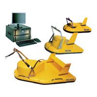
EdgeTech 3200-XS Hardware Manual (76 pages)
SUB-BOTTOM SYSTEM
Brand:
EdgeTech
| Category:
Marine Equipment
| Size: 4.1 MB
Table of Contents
Attention - Read this First
3
Warnings, Cautions, and Notes
3
Hardware Variations and Compatibility
4
About this Document
5
Liability
5
Revision History
5
Warranty Statement
6
Software Service Overview
7
Software Updates and Enhancements
7
Returned Material Authorization
8
RMA Purpose
8
Customer Service
8
Company Background
10
Table of Contents
11
List of Figures
14
1 Overview
17
Advantages of Full Spectrum CHIRP Technology
17
Separate Acoustic Projectors and Receivers
17
High Repeatability
18
High Signal-To-Noise Ratio
18
High Resolution
18
Additional Processing Gain
18
Gaussian Shaped Amplitude Spectrum Outgoing Pulse
19
Reduction of Side Lobes
19
Full Spectrum CHIRP Technology Applications
19
Main System Components
20
3200 Rack Mount Processor
20
Figure 1-1: 3200 Rack Mount Processor
21
SB-424, SB-216S, and SB-512I Tow Vehicles
22
Figure 1-2: Tiger and Mother Boards Inside 3200-XS Topside Processor
22
Figure 1-3: SB-424, SB-216S, and SB-512I Tow Vehicles
23
Tow Cable
24
Figure 1-4: 75-Meter Kevlar Reinforced Tow Cable
24
2 Specifications
25
3200 Rack Mount Processor
25
Rack Mount General Specifications
25
Table 2-1: Rack Mount General Specifications
25
Processor Unit Specs
26
Power Amplifier
26
Power Output
26
Table 2-2: 3200-XS Topside Processor Specs
26
Table 2-3: Power Amplifier Specs: Power Output
26
Performance
27
Construction
27
Tiger Board Description
27
Table 2-4: Power Amplifier Specs: Performance
27
Table 2-5: Power Amplifier Specs: Construction
27
Acquisition Board
28
Carrier Board
28
Figure 2-1: Tiger Board Set: Carrier (Front View) - 0006013
28
Figure 2-2: Tiger Board Set: Carrier (Rear View) - 0006013
28
Figure 2-3: Tiger Board Set: Acquisition PCB - 0014231
28
Figure 2-4: Tiger Board Set: SIBU Aka Sonar Interface Board - 0011637
28
Sonar Board
28
Figure 2-1: Tiger Board Set: Carrier (Front View) – 0006013
29
SB-424, SB-216S, and SB-512I Tow Vehicles
30
Table 2-6: Tow Vehicle Specifications
31
Mechanical Drawings
32
Figure 2-5: SB-216 Towfish Outline Drawing
33
Figure 2-6: SB-424 Towfish Outline Drawing
34
Figure 2-7: SB-512I Towfish Outline Drawing
35
Kevlar Reinforced Tow Cable Specifications
36
Table 2-7: 75-Meter Kevlar Reinforced Tow Cable Specifications
36
3 Setup and Activation
37
Unpacking and Inspection
37
Power Requirements
38
Use of an Uninterruptable Power Supply
38
Changing to a Non-US Power Plug
38
Navigation Interface
38
Topside Placement
38
Table 3-1: AC Power Cord Wiring
38
Rack Mount Controls and Indicators
39
Figure 3-1: Front Panel of 3200-XS Rack Mount Topside
40
Figure 3-2: Topside Rear Panel Controls and Connections
41
Rack Mount Deck Unit Connections
42
Connecting the System Components
43
Connecting and Attaching the Tow Cable to the Tow Vehicle
43
Figure 3-3: Reinforced Cable Attached to SB-216S Tow Vehicle
44
Figure 3-4: Recommended Method for Dressing and Strain Relieving Tow Cable
44
Connecting the Rack Mount Topside
45
Activating the System
45
Pre-Deployment Tests
46
Figure 3-5: the DISCOVER Sub-Bottom Main Window
46
Figure 3-6: Successful Self-Test
47
Figure 3-7: NET: on
47
Figure 3-8: the Sub-Bottom Control Tab
47
Figure 3-9: Tap Test
48
Tow Vehicle Deployment
49
Obtaining the Best Sonar Imagery When Towing
49
Conducting Sediment Classification Surveys When Towing
50
4 Maintenance
51
Periodic Maintenance
51
Cleaning the 3200-XS Topside Processor
51
Cleaning the Tow Vehicle and Tow Cable after Use
51
Inspecting and Cleaning the Underwater Connectors
51
Storage
52
Restoring the Operating System
52
Disassembling and Reassembling a Tow Vehicle
52
Disassembling a Tow Vehicle
53
Figure 4-1: Retaining Ring and Locking Sleeve Removed
53
Figure 4-2: Male Connector
53
Figure 4-3: Removing the 7/16-Inch Bolts Securing the Teardrop Cover to the Tow Vehicle
54
Figure 4-4: Removing the Teardrop Cover
54
Reassembling a Tow Vehicle
55
Figure 4-5: Teardrop Cover Removed
55
Figure 4-6: Removing 7/16 and ½ Inch Bolts and Nuts
55
Figure 4-7: SB-424, SB-216S and SB-512I Tow Vehicle Internals
56
5 Troubleshooting
57
Rack Mount Deck Unit Troubleshooting
58
Table 5-1: Rack Mount Troubleshooting
59
Connector Pinouts
60
Figure 5-1: SEA CABLE Connector-Female Face View
60
Table 5-2: SEA CABLE Connector Pinouts
60
Figure 5-2: Male Marshal Connector - 86-5MC (Tow Vehicle to Tow Cable Connection)
61
Figure 5-3: Female Marshal Connector - 86-5FC (Tow Cable to Tow Vehicle Connection)
61
Table 5-3: Tow Cable Connections
61
Table 5-4: SEA CABLE Female Connector
61
Wiring and Connector Pinout Drawings
62
Figure 5-4: Wiring Harness, Rack Mount Deck Unit - 0004957
63
Figure 5-5: Wiring Diagram, Spider Box, SB-424 Tow Vehicle - 0003174
64
Figure 5-6: Wiring Diagram, SB-424 Tow Vehicle - 0016154
65
Figure 5-7: Wiring Diagram, Spider Box, SB-216S Tow Vehicle - 0003173
66
Figure 5-8: Wiring Diagram, SB-216S Tow Vehicle - 0016153
67
Figure 5-9: Wiring Diagram, Spider Box, SB-512I Tow Vehicle - 0003172
68
Figure 5-10: Wiring Diagram, SB-512I Tow Vehicle
69
Figure 5-11: Wiring Diagram, 75-Meter Kevlar Reinforced Tow Cable - 002980
70
Figure 5-12: Wiring Diagram, 200-Meter Kevlar Reinforced Tow Cable - 0011685
71
A.0: System Restore
73
B.0: Faq
75
Advertisement
Edgetech 3200-XS User Manual (74 pages)
Sub-Bottom Profiling System
Brand:
Edgetech
| Category:
Marine Equipment
| Size: 22.61 MB
Table of Contents
Warning-Read this First
3
Radiation
3
High Voltages
3
Improper Line Voltage
3
Preface
4
Warnings, Cautions and Notes
5
Liability
5
Warranty
6
Software Service Agreement
7
Software Updates and Enhancements
7
Software Performance Report
7
Software Telephone, Facsimile and E-Mail Support
8
Software Service Agreement Fee
8
Returned Material Authorization
9
Customer Service
10
Table of Contents
11
List of Figures
14
Overview
17
Company Background
17
Advantages of Full Spectrum Chirp Technology
17
Separate Acoustic Projectors and Receivers
18
High Repeatability
18
High Signal-To-Noise Ratio
18
High Resolution
19
Additional Processing Gain
19
Gaussian Shaped Amplitude Spectrum Outgoing Pulse
19
Reduction of Side Lobes
19
Full Spectrum Chirp Technology Applications
20
Main System Components
21
Deck Unit
21
Figure 1-1: Deck Unit
21
Figure 1-2: Tiger and Mother Boards Inside 3200-XS Topside Processor
22
SB-424, SB-216S and SB-512I Tow Vehicles
23
75-Meter Kevlar Reinforced Tow Cable
23
Figure 1-3: 75-Meter Kevlar Reinforced Tow Cable
23
Figure 1-4: SB-424, SB-216S and SB-512I Tow Vehicles
24
Tiger Board Description
25
Carrier Board
25
Acquisition Board
25
Sonar/Ide Board
25
Figure 1-5: Tiger Board Set
26
Specifications
27
Deck Unit
27
Deck Unit General
27
Table 2-1: Deck Unit General Specifications
27
3200-XS Topside Processor
28
Table 2-2: 3200-XS Topside Processor Specifications
28
Power Amplifier
29
SB-424, SB-216S and SB-512I Tow Vehicles
29
Table 2-3: Table
29
75-Meter Kevlar Reinforced Tow Cable
31
Setup and Test
33
Unpacking and Inspection
33
Power Requirements
34
Use of an Uninterruptable Power Supply
34
Selecting the Power Amplifier Input Power Voltage
34
Changing to a Non-US Power Plug
34
Navigation Interface
34
Locating the Deck Unit
35
Deck Unit Controls and Indicators
35
Figure 3-1: Deck Unit Back Side
36
Deck Unit Connections
39
Connecting the System Components
40
Connecting and Attaching the 75-Meter Kevlar Reinforced Tow Cable to the Tow Vehicle
40
Figure 3-4: a 75-Meter Kevlar Reinforced Tow Cable Shown Connected and Attached
41
Figure 3-5: Recommended Method for Dressing and Strain Relieving the Tow Cable
41
Connecting the Deck Unit
42
System Activation and Test
42
Activating the System
43
Performing the Predeployment Checks
43
Figure 3-6: the DISCOVER 3200SB Main Window
44
Figure 3-7: the Options Dialog Box, Sonar Control Tab
44
Tow Vehicle Deployment
45
Obtaining the Best Sonar Imagery When Towing
46
Conducting Sediment Classification Surveys When Towing
46
Maintenance and Troubleshooting
49
Periodic Maintenance
49
Cleaning the Air Filter in the 3200-XS Topside Processor
49
Cleaning the Tow Vehicle and Tow Cable after Use
49
Inspecting and Cleaning the Underwater Connectors
50
Storage
50
Restoring the Operating System to the Hard Drive
50
Disassembling and Reassembling a Tow Vehicle
51
Disassembling a Tow Vehicle
51
Figure 4-1: Retaining Ring and Locking Sleeve
51
Figure 4-2: Retaining Ring and Locking Sleeve Removed
51
Figure 4-5: Removing the Teardrop Cover
53
Reassembling the Tow Vehicle
54
Figure 4-6: Teardrop Cover Removed
54
Figure 4-7: Removing 7/16 and 1/2-Inch Bolts and Nuts Securing the Top Cover of the Tow Vehicle Body
54
Troubleshooting
55
Table 4-1: System Troubleshooting Guide
55
Connector Pinouts
59
Figure 4-9: Tow Vehicle Tow Cable Connector-Male, Face View
59
Table 4-2: SEA CABLE Connector Pinouts
59
Table 4-3: Tow Vehicle Tow Cable Connector Pinouts
59
Wiring and Connector Pinout Drawings
60
Table 4-4: List of Wiring and Connector Pinout Drawings
60
Printer Connections
69
Table A-1: Table
69
A.1 EPC Model 1086
70
EPC Model HSP-100
70
Raytheon Model TDU-850
71
Frequently Asked Questions
73
Advertisement
Related Products
Edgetech 3100
Edgetech 3300
Edgetech 3400
Edgetech Model 3100P Sub-bottom Sonar System
Edgetech 2050-DSS
Edgetech 4200-FS
Edgetech 4380 MULTIBEACON
Edgetech 6205S2
Edgetech 701 DIGITAL LINK
EdgeTech 8242XS
EdgeTech Categories
Marine Equipment
Sonar
Measuring Instruments
Fishing Equipment
Scanner
More EdgeTech Manuals
Login
Sign In
OR
Sign in with Facebook
Sign in with Google
Upload manual
Upload from disk
Upload from URL