
Related Manuals for WEST PAM-199-P-PDP


Summary of Contents for WEST PAM-199-P-PDP
- Page 1 Technical Documentation PAM-199-P-PDP Universal power amplifier with ProfibusDP interface...
-
Page 2: Table Of Contents
ACC (Auto adaptation of the closed loop current controller) ..............26 5.6.6 PPWM (Solenoid current controller P gain) ....................27 5.6.7 IPWM (Solenoid current controller I gain) ....................27 5.6.8 ST (Status request) ............................ 28 Process data (Monitoring) ..........................28 Appendix ..................................29 Page 2 of 37 PAM-199-P-PDP 05.06.2020... - Page 3 Feedback via Profibus ............................33 Parameterizing via Profibus ..........................34 7.6.1 Funktionsweise ............................34 7.6.2 Parameter list mode 195 ..........................34 7.6.3 Parameter list mode 196 ..........................35 Realization / Example ............................36 Notes ..................................37 Page 3 of 37 PAM-199-P-PDP 05.06.2020...
-
Page 4: General Information
1 General Information Order Number PAM-199-P-PDP - universal power amplifier for directional valves or two pressure or throttle valves with ProfibusDP interface Special versions PAM-199-P-PDP-S1 - universal power amplifier for directional valves or two pressure or throttle valves with ProfibusDP interface and separate power supply for the Profibus interface... -
Page 5: Symbols Used
We reserve the right to make technical modifications due to further development of the product described in this manual. The technical information and dimensions are non-binding. No claims may be made based on them. This document is protected by copyright. Page 5 of 37 PAM-199-P-PDP 05.06.2020... -
Page 6: Safety Instructions
The module may not be used in an explosive environment. To ensure adequate cooling the ventilation slots must not be covered. The device must be disposed of in accordance with national statutory provisions. Page 6 of 37 PAM-199-P-PDP 05.06.2020... -
Page 7: Characteristics
Free parameterization of RAMPS, MIN / MAX, PWM, output current and DITHER Range of the rated output current: 0.5… 2.6 A Simple and application orientated parameter settings via WPC-software Failure monitoring and extended function check Page 7 of 37 PAM-199-P-PDP 05.06.2020... -
Page 8: Device Description
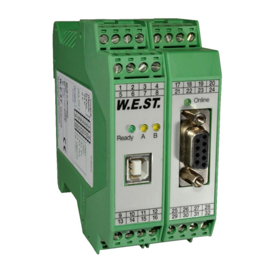
18 19 20 Type plate and terminal pin assignment W.E.ST. PROFIBUS Buchse LEDs Online PROFIBUS connector Ready A Klemmblöcke (steckbar) Terminals (removable) Interface 9 10 11 12 26 27 28 14 15 16 30 31 32 Page 8 of 37 PAM-199-P-PDP 05.06.2020... -
Page 9: Use And Application
Switched inductances (relays and valve coils connected to the same power supply) must always be provided with appropriate overvoltage protection directly at the coil. Page 9 of 37 PAM-199-P-PDP 05.06.2020... -
Page 10: Typical System Structure
This minimal system consists of the following components: (*1) proportional (directional) valve (*2) hydraulic cylinder (*3) PAM-199-P-PDP (*4) interface to PLC with ProfibusDP and digital signals 3.2.2 Function 196 This minimal system consists of the following components: (*1) proportional valve(s) -
Page 11: Method Of Operation
WPC program can be activated. CAUTION! The WPC program will take the whole control over the device then. The Enable signal at PIN 8 and the bus interface are inoperable in this case. Page 11 of 37 PAM-199-P-PDP 05.06.2020... -
Page 12: Function Modes And Technical Description
Not active when SENS = OFF. YELLOW LED in the middle position = Activity of solenoid A. LED in the right position = Activity of solenoid B. Online LED Profibus – communication is active. PDP GREEN Page 12 of 37 PAM-199-P-PDP 05.06.2020... -
Page 13: Input And Output Signals
PIN 8 This digital input signal linked with the software enabling initializes the application. READY output: PIN 1 Module is ready, no errors are detected OFF: ENABLE is deactivated or an error was detected. Page 13 of 37 PAM-199-P-PDP 05.06.2020... -
Page 14: Circuit Diagram
Circuit diagram Page 14 of 37 PAM-199-P-PDP 05.06.2020... -
Page 15: Typical Wiring
Typical wiring power supply PLC input logic Ready solenoid A PLC output solenoid B Enable 0V (GND) power supply extension card profibus power supply powerstage (S1 version) Page 15 of 37 PAM-199-P-PDP 05.06.2020... -
Page 16: Technical Data
-20… 70 Storage temperature [°C] Humidity < 95 (non-condensing) Connections Communication USB type B Profibus D-SUB p pin Plug connectors 4-pole terminal blocks via the DIN mounting rail 61000-6-2: 8/2005 61000-6-4: 6/2007 ; A1:2011 Page 16 of 37 PAM-199-P-PDP 05.06.2020... -
Page 17: Parameter
Parameters of the power stage CURRENT 1000 Rated solenoid current DAMPL 0.01 % Dither amplitude DFREQ Dither frequency 2604 PWM frequency Current loop auto adjustment PPWM P-Gain of the current loop IPWM I-Gain of the current loop Page 17 of 37 PAM-199-P-PDP 05.06.2020... -
Page 18: Parameter List 196
0.01 % Dither amplitude DAMPL:B 0.01 % DFREQ:A Dither frequency DFREQ:B PWM:A 2604 PWM frequency PWM:B 2604 Current loop auto adjustment PPWM:A P-Gain of the current loop PPWM:B IPWM:A I-Gain of the current loop IPWM:B Page 18 of 37 PAM-199-P-PDP 05.06.2020... -
Page 19: Basic Parameters
CAUTION: If the address is changed via the Profibus, the ”126” remains in the parameter list. The actual address for communicating with the module is still the one which was chosen via the Profibus. Page 19 of 37 PAM-199-P-PDP 05.06.2020... -
Page 20: Sens (Failure Monitoring)
CAUTION: If CC command is used, parameters MIN, MAX and TRIGGER have to be considered. CC and those commands affect each other. Pay attention to that if it is necessary to use both kind of settings at the same time. Page 20 of 37 PAM-199-P-PDP 05.06.2020... -
Page 21: Input Signal Adaption
The first quadrant means the ramp up and the second quadrant means the ramp down time. The ramp time is related to 100 % signal step. The ramp function is adjustable independently for each channel. AA:UP AA:DOWN AB:DOWN AB:UP Page 21 of 37 PAM-199-P-PDP 05.06.2020... -
Page 22: Output Signal Adaption
For the input of the characteristics linearization, the WPC-300 program provides a table and a graphic data input. The input signal is mapped on to the X-axis and the output signal is mapped on to the Y-axis. Page 22 of 37 PAM-199-P-PDP 05.06.2020... - Page 23 For the input of the characteristics linearization, the WPC-300 program provides a table and a graphic data input. The input signal is mapped on to the X-axis and the output signal is mapped on to the Y-axis. Page 23 of 37 PAM-199-P-PDP 05.06.2020...
-
Page 24: Min (Overlap Compensation)
This dead band is necessary, in order to avoid unrequested activations caused by small variations of the input signal. If this module is used in a position controls, the TRIGGER value should be reduced (typical: 1…10). Page 24 of 37 PAM-199-P-PDP 05.06.2020... -
Page 25: Parameters Of The Power Stage
The DITHER frequency should not be confused with the PWM frequency. In some proportional valve documentations a mistake is done by the definition of the DITHER / PWM frequency. It is recognizable by missing information about the DITHER amplitude. Page 25 of 37 PAM-199-P-PDP 05.06.2020... -
Page 26: Pwm (Pwm Frequency)
5.6.5 ACC (Auto adaptation of the closed loop current controller) Command Parameters Unit Group x= ON|OFF Operation mode of the closed loop current control. In automatic mode PPWM and IPWM are calculated depending on the preset PWM-frequency. OFF: Manual adjustment. Page 26 of 37 PAM-199-P-PDP 05.06.2020... -
Page 27: Ppwm (Solenoid Current Controller P Gain)
Typical values are: PPWM = 1… 3 and IPWM = 40… 80. If the PWM frequency is > 1000 Hz, the default values of PPWM = 7 and IPWM = 40 should be chosen. Page 27 of 37 PAM-199-P-PDP 05.06.2020... -
Page 28: St (Status Request)
Command value to current controller channel B Output current to solenoid A Output current to solenoid B The process data are the variable values which can be continuously observed on the monitor or on the oscillo- scope. Page 28 of 37 PAM-199-P-PDP 05.06.2020... -
Page 29: Appendix
Internal data error: execute the command / press the button SAVE to delete the data error. The system reloads the DEFAULT data. With the WPC-300 operating program the failure can be localized directly via the monitor. Page 29 of 37 PAM-199-P-PDP 05.06.2020... -
Page 30: Status Information
EEPROM – Data error of the memory, SAVE should be executed SYS_ERROR – Internal error SOLENOID A – Error (e.g. broken wire) at output A SOLENOID B – Error (e.g. broken wire) at output B Page 30 of 37 PAM-199-P-PDP 05.06.2020... -
Page 31: Profibus Interface
The GSD-file is available at the address: http://www.w-e-st.de/files/software/hms_1810.gsd File: hms_1810.gsd In the setting of the transfer bytes, 16 bytes (8 words consistent) are necessary as IN/OUT variables. Page 31 of 37 PAM-199-P-PDP 05.06.2020... -
Page 32: Commands Via Profibus
1 = Enable Enable channel B 1 = Enable PARAMODE 1 = active PARAVALID Rising edge Hardware and software ENABLE are linked with each other. Means the system is only ready if both signals are available. Page 32 of 37 PAM-199-P-PDP 05.06.2020... -
Page 33: Feedback Via Profibus
1 = Parameterization OK PARA_ACT 1 = Parameter transmitted Error at solenoid A IA ERROR Error at solenoid B IB ERROR READY A 1 = Channel A ready READY B 1 = Channel B ready Page 33 of 37 PAM-199-P-PDP 05.06.2020... -
Page 34: Parameterizing Via Profibus
0x1388… 0x2710 0x2012 MAX:A 0x1388… 0x2710 0x2013 MAX:B 0x0000… 0x0BB8 0x2014 TRIGGER 0x01F4… 0x0A28 0x2020 CURRENT 0x0000… 0x0BB8 0x2021 DAMPL 0x003C… 0x0190 0x2024 DFREQ 0x0001… 0x0014 0x2027 0x0000… 0x001E 0x2030 PPWM 0x0001… 0x0064 0x2031 IPWM Page 34 of 37 PAM-199-P-PDP 05.06.2020... -
Page 35: Parameter List Mode 196
0x2023 DAMPL:B 0x003C… 0x0190 0x2025 DFREQ:A 0x003C… 0x0190 0x2026 DFREQ:B 0x0001… 0x0014 0x2028 PWM:A 0x0001… 0x0014 0x2029 PWM:B 0x0000… 0x001E 0x0032 PPWM:A 0x0000… 0x001E 0x0033 PPWM:B 0x0000… 0x001E 0x0034 IPWM:A 0x0000… 0x001E 0x0035 IPWM:B Page 35 of 37 PAM-199-P-PDP 05.06.2020... -
Page 36: Realization / Example
20. The adjustable values are described in chapter PWM 5.6.4. Caution: Changed parameter settings are directly active. So if parameterizing at a running system (enable is set) is necessary, it has to be done carefully. Page 36 of 37 PAM-199-P-PDP 05.06.2020... -
Page 37: Notes
8 Notes Page 37 of 37 PAM-199-P-PDP 05.06.2020...
Need help?
Do you have a question about the PAM-199-P-PDP and is the answer not in the manual?
Questions and answers