
Related Manuals for WEST PAM-199-P-IO


Summary of Contents for WEST PAM-199-P-IO
- Page 1 Technical Documentation PAM-199-P-IO Universal power amplifier with IO-Link interface...
-
Page 2: Table Of Contents
IPWM (Solenoid current controller I gain) ..................... 27 PROCESS DATA (Monitoring) ........................28 IO–Link Interface ..............................29 Setpoints from master to device ........................29 Process data from the device to the master ....................30 Page 2 of 34 PAM-199-P-IO 19.06.2024... - Page 3 Parameterisation via IO – Link ........................31 Appendix ................................32 Failure monitoring ............................32 Troubleshooting ............................33 Notes ..................................34 Page 3 of 34 PAM-199-P-IO 19.06.2024...
-
Page 4: General Information
1 General Information 1.1 Product Name PAM-199-P-IO universal power amplifier for directional valves or two pressure or throttle valves with IO-Link interface Alternative products PAM-199-P-PFN universal power amplifier for directional valves or two pressure or throttle valves with Profinet interface... -
Page 5: Symbols Used
We reserve the right to make technical modifications due to further development of the product described in this manual. The technical information and dimensions are non-binding. No claims may be made based on them. This document is protected by copyright. Page 5 of 34 PAM-199-P-IO 19.06.2024... -
Page 6: Safety Instructions
• The module may not be used in an explosive environment. • To ensure adequate cooling the ventilation slots must not be covered. • The device must be disposed of in accordance with national statutory provisions. Page 6 of 34 PAM-199-P-IO 19.06.2024... -
Page 7: Characteristics
IO-Link setpoint value channels A and B. The output current of the PAM-199-P-IO is closed loop controlled and therefore independent from the power supply and the solenoid resistance. The output stage is monitored for cable breakdown, is short circuit proof and disables the power stage in case of an error. -
Page 8: Device Description
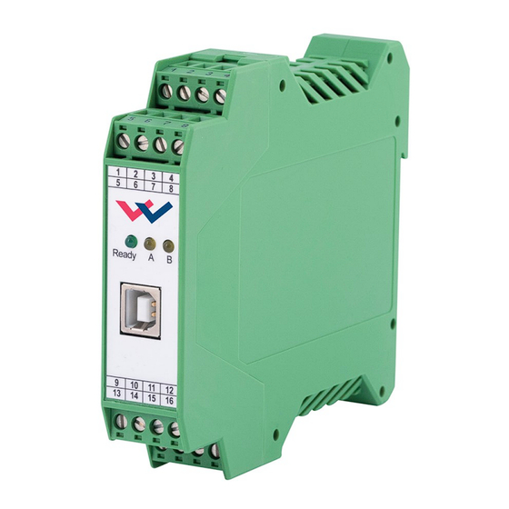
Made in Germany Date: Add.: W.E.ST. Elektronik D-41372 Niederkrüchten Homepage: http://www.w-e-st.de Typenschild und Anschlussbelegung Type plate and terminal pin assignment W.E.ST. Ready Klemmblöcke (steckbar) LEDs Terminals (removable) USB-Interface 9 10 11 12 14 15 16 Page 8 of 34 PAM-199-P-IO 19.06.2024... -
Page 9: Use And Application
Switched inductances (relays and valve coils) which are connected to the same power supply must always be provided with appropriate overvoltage protection directly at the coil. Page 9 of 34 PAM-199-P-IO 19.06.2024... -
Page 10: Typical System Structure
2.2.2.1 Function DIR This minimal system consists of the following components: (*1) proportional (directional) valve (*2) hydraulic cylinder (*3) PAM-199-P-IO (*4) IO-Link interface to PLC 2.2.2.2 Function IND This minimal system consists of the following components: (*1) proportional valve(s) (*2) -
Page 11: Method Of Operation
WPC program can be activated. CAUTION! The WPC program will take the whole control over the device then. The Enable signal at PIN 6 and the bus interface are inoperable in this case. Page 11 of 34 PAM-199-P-IO 19.06.2024... -
Page 12: Remote Control
The device can be simply controlled via these input signals. CAUTION: All safety aspects must be thoroughly checked when working with the RC (Remote Control) mode. In this mode, the module is controlled directly and the machine control cannot in- fluence the module. Page 12 of 34 PAM-199-P-IO 19.06.2024... -
Page 13: Technical Description
The two yellow LEDs flash alternately in 1 s cycles: The non-volatile stored parameter data is inconsistent! To acknowledge this error, the data must be saved in the WPC using the SAVE command / button. Page 13 of 34 PAM-199-P-IO 19.06.2024... -
Page 14: Block Diagram
3.3 Block diagram 3.4 Typical wiring Solenoid B Solenoid A Enable Ready Power Supply Screen free analog inputs (0... 10V or 4... 20mA) +24 V IO-Link Page 14 of 34 PAM-199-P-IO 19.06.2024... -
Page 15: Technical Data
Storage temperature [°C] -20… 70 Humidity < 95 (non-condensing) Connections Communication USB type B Plug connectors 4 x 4-pole terminal blocks via the DIN mounting rail EN 61000-6-2: 8/2005 EN 61000-6-3: 6/2007 + A1:2011 Page 15 of 34 PAM-199-P-IO 19.06.2024... -
Page 16: Parameters
Deadband compensation trigger point 1028/2 The indices of the coordinates for the bipolar characteristic are assigned in the order X-10/Y-10/X-9/Y-9...X10/Y10. The indices of the coordinates for the unipolar characteristics are assigned in the order X0/Y0/X1/Y1...X10/Y10. Page 16 of 34 PAM-199-P-IO 19.06.2024... - Page 17 WPC versions with a decimal point shift of two places, example: 100.00 % - > input "10000". This also applies to the IO-Link parameterisation. In most programming environments, however, these parameter values, as defined in the IODD file, are also displayed correctly as a floating point number. Page 17 of 34 PAM-199-P-IO 19.06.2024...
-
Page 18: Basic Parameters
Normally the monitoring functions are always active because otherwise no errors are detectable via the READY output. Deactivating is possible mainly for troubleshooting. Text selection parameters are transmitted coded as integers via IO-Link. The parameter descriptions contain these nu- merical equivalents as information, marked in blue colour. Page 18 of 34 PAM-199-P-IO 19.06.2024... -
Page 19: Function (Choosing Operation Mode)
CAUTION: If CC command is used, parameters MIN, MAX and TRIGGER have to be considered. CC and those commands affect each other. Pay attention to that if it is necessary to use both kind of settings at the same time. Page 19 of 34 PAM-199-P-IO 19.06.2024... -
Page 20: Signal Adaption
The first quadrant means the ramp up and the second quadrant means the ramp down time. The ramp time is related to 100 % signal step. The ramp function is adjustable independently for each channel. AA:UP AA:DOWN AB:UP AB:DOWN Page 20 of 34 PAM-199-P-IO 19.06.2024... -
Page 21: Signal:9/:10 (Type Of Free Input Signals)
This command enables direction switching of the output signal in directional valve mode. A positive setpoint leads to control of solenoid A, a negative one acts on solenoid B A negative setpoint leads to control of solenoid A, a positive one acts on solenoid B Page 21 of 34 PAM-199-P-IO 19.06.2024... -
Page 22: Cc (Characteristics Linearization)
For the input of the characteristics linearization, the WPC-300 program provides a table and a graphic data input. The input signal is mapped on to the X-axis and the output signal is mapped on to the Y-axis. Page 22 of 34 PAM-199-P-IO 19.06.2024... - Page 23 For the input of the characteristics linearization, the WPC-300 program provides a table and a graphic data input. The input signal is mapped on to the X-axis and the output signal is mapped on to the Y-axis. Page 23 of 34 PAM-199-P-IO 19.06.2024...
-
Page 24: Min (Overlap Compensation)
This dead band is necessary, in order to avoid unrequested activations caused by small variations of the input signal. If this module is used in a position controls, the TRIGGER value should be reduced (typical: 1…10). Page 24 of 34 PAM-199-P-IO 19.06.2024... -
Page 25: Parameters Of The Power Stage
The DITHER frequency should not be confused with the PWM frequency. In some proportional valve documentations a mistake is done by the definition of the DITHER / PWM frequency. It is recognizable by missing information about the DITHER amplitude. Page 25 of 34 PAM-199-P-IO 19.06.2024... -
Page 26: Pwm (Pwm Frequency)
4.5.5 ACC (Auto adaptation of the closed loop current controller) Command Parameters Unit Group ACC/:A/:B x ON(2)|OFF(1) Operation mode of the closed loop current control. In automatic mode PPWM and IPWM are calculated depending on the preset PWM-frequency. OFF: Manual adjustment. Page 26 of 34 PAM-199-P-IO 19.06.2024... -
Page 27: Ppwm (Solenoid Current Controller P Gain)
Typical values are: PPWM = 1… 3 and IPWM = 40… 80. If the PWM frequency is > 1000 Hz, the default values of PPWM = 7 and IPWM = 40 should be chosen. Page 27 of 34 PAM-199-P-IO 19.06.2024... -
Page 28: Process Data (Monitoring)
PIN9 Free input signals (display only available if the as- sociated input has been activated) PIN10 The process data are the variables which can be observed continuously on the monitor or on the oscilloscope. Page 28 of 34 PAM-199-P-IO 19.06.2024... -
Page 29: Io-Link Interface
Definition of the control word: Byte 0 – Control word 1 High Function ENABLE(A) Enable the unit (DIR) or channel A Byte 1 – Control word 1 Low Funktion ENABLE B Enable channel B (IND) Page 29 of 34 PAM-199-P-IO 19.06.2024... -
Page 30: Process Data From The Device To The Master
The criterion is working data communication between the processors for the IO link and the power amplifier. Higher volt- ages (see technical data) are required to operate the power stage. This means that a set !APILOWVERR flag alone cannot be used to conclude that the voltage is sufficient to energise the solenoids. Page 30 of 34 PAM-199-P-IO 19.06.2024... -
Page 31: Parameterisation Via Io-Link
The numerical values of the selection parameters are assigned in colour to the respective selection options in the descriptions of the previous chapters, for example " ". In the case of numerical parameters, the units and value ranges specified there apply in each case. Page 31 of 34 PAM-199-P-IO 19.06.2024... -
Page 32: Appendix
WPC before remote control opera- tion is switched off. EEPROM Data error Both output stages are deactivated. The (when switching on) module can only be activated by saving the parameters again! Page 32 of 34 PAM-199-P-IO 19.06.2024... -
Page 33: Troubleshooting
PWM frequency = 2600 Hz (higher frequency), the dither has to be aligned to the valve (amplitude and frequency). PWM frequency = 100… 400 Hz (lower frequency), the dither amplitude is set to 0 % (disabled). Page 33 of 34 PAM-199-P-IO 19.06.2024... -
Page 34: Notes
7 Notes Page 34 of 34 PAM-199-P-IO 19.06.2024...
Need help?
Do you have a question about the PAM-199-P-IO and is the answer not in the manual?
Questions and answers