
Related Manuals for WEST PAM-198-P


Summary of Contents for WEST PAM-198-P
- Page 1 Technical Documentation PAM-198-P Power amplifier for directional valves with feedback position control...
-
Page 2: Table Of Contents
Integrator control ............................28 Parameters of the power stage........................... 29 5.6.1 CURRENT (Nominal solenoid current) ...................... 29 5.6.2 DAMPL (Dither amplitude) ......................... 29 5.6.3 DFREQ (Dither frequency) ......................... 29 5.6.4 PWM (PWM frequency) ..........................29 Page 2 of 33 PAM-198-P 05.06.2020... - Page 3 PPWM (Solenoid current controller P gain) ....................30 5.6.7 IPWM (Solenoid current controller I gain) ....................30 Process data (Monitoring) ........................... 31 Appendix ..................................31 Failure monitoring ............................... 31 Troubleshooting ..............................32 Notes ..................................33 Page 3 of 33 PAM-198-P 05.06.2020...
-
Page 4: General Information
1 General Information Order Number PAM-198-P - power amplifier for directional valves with feedback position control Scope of supply The scope of supply includes the module plus the terminal blocks which are a part of the housing. The Profibus plug, interface cables and further parts which may be required should be ordered separately. -
Page 5: Symbols Used
We reserve the right to make technical modifications due to further development of the product described in this manual. The technical information and dimensions are non-binding. No claims may be made based on them. This document is protected by copyright. Page 5 of 33 PAM-198-P 05.06.2020... -
Page 6: Safety Instructions
The module may not be used in an explosive environment. To ensure adequate cooling the ventilation slots must not be covered. The device must be disposed of in accordance with national statutory provisions. Page 6 of 33 PAM-198-P 05.06.2020... -
Page 7: Characteristics
Free parameterization of RAMPS, MIN und MAX, output current, DITHER (frequency, amplitude) Nominal output current range up to 2.6 A Simple and application orientated parameter settings via WPC-software Failure monitoring and extended function check Page 7 of 33 PAM-198-P 05.06.2020... -
Page 8: Device Description
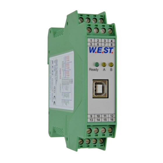
Made in Germany Date: Add.: W.E.ST. Elektronik D-41372 Niederkrüchten Homepage: http://www.w-e-st.de Typenschild und Anschlussbelegung Type plate and terminal pin assignment W.E.ST. LEDs Ready Klemmblöcke (steckbar) Terminals (removable) interface 9 10 11 12 14 15 16 Page 8 of 33 PAM-198-P 05.06.2020... -
Page 9: Use And Application
Switched inductances (relays and valve coils connected to the same power supply) must always be provided with appropriate overvoltage protection directly at the coil. Page 9 of 33 PAM-198-P 05.06.2020... -
Page 10: Typical System Structure
Typical system structure This minimum example system contains of following components: (*1) Proportional valve (*2) Spool position sensor (*3) Control module PAM-198-P (*4) Interface to the PLC Page 10 of 33 PAM-198-P 05.06.2020... -
Page 11: Method Of Operation
In open loop control mode the power stage can be controlled by the feed forward function which leads the command value directly to the output. In closed loop control mode the control deviation and parameterizing of the controller define the output signal. Page 11 of 33 PAM-198-P 05.06.2020... -
Page 12: Commissioning
The valve can now be controlled by the analog command value (depending on the settings). Optimizing settings Now the adjustment can be optimized. The PID controller has to be adapted to the relative application and its requirements. Page 12 of 33 PAM-198-P 05.06.2020... -
Page 13: Function Modes And Technical Description
Error detected Current to the solenoid A; the intensity is proportional to the actual output current. YELLOW A YELLOW B Current to the solenoid B; the intensity is proportional to the actual output current. Page 13 of 33 PAM-198-P 05.06.2020... -
Page 14: Circuit Diagram
Circuit diagram Page 14 of 33 PAM-198-P 05.06.2020... -
Page 15: Typical Wiring
Solenoid-B 8V PIN 12 SPS / PLC / SENSOR 0... 10 V +In PIN 9 +In PIN 9 + 14 -In PIN 10 -In PIN 10 + 13 GND PIN 11 GND PIN 11 Page 15 of 33 PAM-198-P 05.06.2020... -
Page 16: Technical Data
< 95 (non-condensing) Vibration resistance IEC 60068-2-6 (Category C) Connections Communication USB type B Plug connectors 4 x 4-pole terminal blocks via the DIN mounting rail EN 61000-6-2: 8/2005 EN 61000-6-4: 6/2007 + A1:2011 Page 16 of 33 PAM-198-P 05.06.2020... -
Page 17: Parameter
Parameterizing linearization by 10 points Deadband compensation / direction depending scaling MIN:A 0,01 % Deadband compensation MIN:B 0,01 % MAX:A 10000 0,01 % Output scaling MAX:B 10000 0,01 % TRIGGER 0,01 % Treshold for deadband compensation Page 17 of 33 PAM-198-P 05.06.2020... - Page 18 CURRENT 1000 Solenoid nominal current DFREQ Dither frequency DAMPL 0,01 % Dither amplitude 2604 PWM frequency Automatical adjustment of the current controller PPWM P-gain of the current controller IPWM I-gain of the current controller Page 18 of 33 PAM-198-P 05.06.2020...
-
Page 19: Basic Parameters
But it can also be useful here to optimize the feed forward and offset settings before activating the PID controller. Page 19 of 33 PAM-198-P 05.06.2020... -
Page 20: Ccmode (Activation Of The Characteristic Linearization)
Auto reset mode. All monitoring functions are active. If the failure does not exist anymore, the mod- ule automatically resumes to work. Normally the monitoring functions are always active because otherwise no errors are detectable via the READY output. Deactivating is possible especially for troubleshooting. Page 20 of 33 PAM-198-P 05.06.2020... -
Page 21: Input Signal Adaption
(SIGNAL:U = 2S-). If higher this value should be taken for B. At last dou- ble up the A value. For this adjustment procedure the remote control mode of the module can be used which can be handled easily by the WPC-300 program. Page 21 of 33 PAM-198-P 05.06.2020... -
Page 22: Signal:u (Type And Polarity Of The Control Signal)
U < 0 -> Controlling IA 5.3.3 VA:OFFSET (Zero point setting) Command Parameters Unit Group VA:OFFSET x= 1… 10000 0.01 % IO_CONF Using valves with one solenoid this parameter defines the basic current for the zero position. Page 22 of 33 PAM-198-P 05.06.2020... -
Page 23: Va:min (Minimum Control)
The values of VA:MAX can be used for example to realize an asymmetry of the solenoid currents between both directions. VA:MAX:A Standard compensation VA:MIN:A Input VA:MIN:B VA:TRIGGER VA:MAX:B Page 23 of 33 PAM-198-P 05.06.2020... -
Page 24: Signal Processing
A. According to this the third quadrant represents the acceleration ramp for solenoid B so that the fourth quadrant remains for the deceleration ramp for solenoid B. ATTENTION: Because of internal calculations rounding errors may be occur on the display. Page 24 of 33 PAM-198-P 05.06.2020... -
Page 25: Cc (Characteristics Linearization)
If the CC command is used, the TRIGGER of the MIN/MAX function should be set to 0 and the function should not be used if possible. Both functions influence each other and make the behavior really diffi- cult to evaluate. Page 25 of 33 PAM-198-P 05.06.2020... -
Page 26: Min (Overlap Compensation)
This dead band is necessary, in order to avoid unrequested activations caused by small variations of the input signal. If this module is used in a position controls, the TRIGGER value should be reduced (typical: 1…10). Page 26 of 33 PAM-198-P 05.06.2020... -
Page 27: Parameters Of The Closed Loop Controller
0.. 10 V C:I_DEACT scaling 4.. 20 mA C:D_T1 Spool position controller P-Gain I-Gain D-Gain C:T1 T1 Filter for D-Gain C:FF Feed forward C:I_LIM Integrator limitation C:I_ACT Integrator activation C:I_DEACT Integrator deactivation VA:OFFSET Zero point setting Page 27 of 33 PAM-198-P 05.06.2020... -
Page 28: Integrator Control
An always active integrator would lead to overshoots because of too early pushing the signal. In order to avoid limit cycling the C:I_DZ allows defining a Deadband around the setpoint. Within this range of the control deviation the integrator will be stopped. Page 28 of 33 PAM-198-P 05.06.2020... -
Page 29: Parameters Of The Power Stage
The DITHER frequency should not be confused with the PWM frequency. In some proportional valve documentations a mistake is done by the definition of the DITHER / PWM frequency. It is recognizable by missing information about the DITHER amplitude. Page 29 of 33 PAM-198-P 05.06.2020... -
Page 30: Acc (Auto Adaptation Of The Closed Loop Current Controller)
Typical values are: PPWM = 1… 3 and IPWM = 40… 80. If the PWM frequency is > 1000 Hz, the default values of PPWM = 7 and IPWM = 40 should be chosen. Page 30 of 33 PAM-198-P 05.06.2020... -
Page 31: Process Data (Monitoring)
The power stage and READY output will be deactivated. PIN 1 / 2 EEPROM Data error The power stage and READY output will be deactivated. (monitored during power on procedure) Activation can be realized by saving the parameters. Page 31 of 33 PAM-198-P 05.06.2020... -
Page 32: Troubleshooting
PWM-frequency = 2600 Hz (higher frequency), the dither has to be aligned to the valve (amplitude and frequency). PWM-frequency = 100… 400 Hz (lower frequency), the dither amplitude is set to 0 % (disabled). Page 32 of 33 PAM-198-P 05.06.2020... -
Page 33: Notes
7 Notes Page 33 of 33 PAM-198-P 05.06.2020...