Advertisement
Quick Links
Advertisement

Related Manuals for WEST PAM-392-P


Summary of Contents for WEST PAM-392-P
- Page 1 Technical Documentation PAM-392-P Plug Amplifier for all typical directional control valves...
- Page 2 PPWM (Solenoid current controller P gain) ..................... 24 5.2.22 IPWM (Solenoid current controller I gain) ....................24 PROCESS DATA (Monitoring) ......................... 24 6 Appendix..................................25 Failure monitoring ............................. 25 Troubleshooting..............................25 Additions to setpoint scaling ..........................26 Notes ................................30 Page 2 of 30 PAM-392-P 27.06.2024...
- Page 3 General Information Order number PAM-392-P Power amplifier for proportional valves with +/-10 V or 4… 20 mA input Alternative products PAM-199-P Power amplifier for proportional directional, pressure or throttle valves with +/-10 V or 4... 20 mA setpoint input PAM-199-P-ETC...
- Page 4 We reserve the right to make technical modifications due to further development of the product described in this manual. The technical information and dimensions are non-binding. No claims may be made based on them. This document is protected by copyright. Page 4 of 30 PAM-392-P 27.06.2024...
- Page 5 When not in use the module must be protected from the effects of the weather, contamination and mechanical damage. • The module may not be used in an explosive environment. • The device must be disposed of in accordance with national statutory provisions. Page 5 of 30 PAM-392-P 27.06.2024...
- Page 6 Characteristic curve linearization over 21 XY points • Free parameterization of RAMP, MIN / MAX, output current and DITHER (frequency, amplitude) • Nominal output current up to 2.6 A • Simple and application-oriented parameterization with WPC software Page 6 of 30 PAM-392-P 27.06.2024...
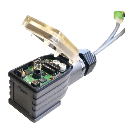
- Page 7 Device Description Status LED Status LED USB-Typ-Mini Solenoid LED Magnetspule LED ~ 86 Type-label Typenschild M12/5 plug M12/5 Steckanschluss Connection Anschluss Front View Draufsicht ~ 43 Page 7 of 30 PAM-392-P 27.06.2024...
- Page 8 According to the classification of the device in accordance with EN55011 / EN55032 / EN 61000-6-4, this is class A equipment, industrial area. This device may cause radio interference in residential areas. In this case, the operator may be required to take appropriate measures. Page 8 of 30 PAM-392-P 27.06.2024...
- Page 9 ATTENTION! The output stage is always active with the supply voltage. The magnetic current should change in proportion to the increasing input signal. Optimize Setting The settings such as ramp time and overlap compensation can now be made. Page 9 of 30 PAM-392-P 27.06.2024...
- Page 10 Description of LED Function Green Green LED: READY indicator Status OFF: No power supply System is operational Flashing: Error condition Yellow Magnetic current dis- A-LED = Current on solenoid A; play B-LED = Current on solenoid B; Page 10 of 30 PAM-392-P 27.06.2024...
- Page 11 The error state is reset in the default setting after the error has been resolved. The output current is regulated, which achieves high accuracy and good dynamics. All commercially availa- ble proportional valves (up to 2.6 A) can be controlled with this power amplifier. Page 11 of 30 PAM-392-P 27.06.2024...
- Page 12 Block diagram PAM-392-P Power supply Power output Solenoid B stage Ramp Power function Input/ Valve Solenoid A output Input Scaling adaptation stage Lineari- sation Differential input PE via DIN-PLUG Communication Control system LIN Bus USB 2.0 Page 12 of 30 PAM-392-P 27.06.2024...
- Page 13 Example 10VDC Example Example Beispiel Beispiel Beispiel Potentiometer 10...0V PLC-Output PLC-Output 4...20 mA Diff.Out / +/- 10 V Joystick SPS-Ausgang SPS-Ausgang The xxx in the designation describes the different variants of the communication adapter. Page 13 of 30 PAM-392-P 27.06.2024...
- Page 14 Valve connector type A Connector 3, Solenoid B Valve connector Type A to line 3x0,5 with Parameterisation interface 0.41 m with 0,15 m PUR halogen-free black USB 2.0 Mini EN 61000-6-2: 2019 EN 61000-6-3: 6/2007 + A1:2011 Page 14 of 30 PAM-392-P 27.06.2024...
- Page 15 Overlap compensation MAX:B % (0.01%) Output scaling TRIGGER % (0.01%) Overlap compensation, Response threshold Power amplifier CURRENT 1000 Nominal current of solenoid coils DFREQ Dither frequency DAMPL % (0.01%) Dither Amplitude 2604 PWM Frequency Page 15 of 30 PAM-392-P 27.06.2024...
- Page 16 Command Default Unit Description Group Automatic solenoid current controller adjustment PPWM Setting the magnetic current regulator at ACC=OFF IPWM Page 16 of 30 PAM-392-P 27.06.2024...
- Page 17 AUTO RESET Mode, all functions are monitored. After the fault state is no longer present, the module automatically returns to the normal operating state. The monitoring function should always be active, so that errors can remain visible via the status display. However, it can be deactivated for troubleshooting purposes. Page 17 of 30 PAM-392-P 27.06.2024...
- Page 18 0 to +/- 100 % by entering FULL:W+ with 9.8 V and FULL:W- with -9.8 V. A further detailed note has been added in the appendix, the new commands replace the previous scaling. Page 18 of 30 PAM-392-P 27.06.2024...
- Page 19 If the signal is greater than 9V or less than 1V, the signal is outside the permitted range and an error is rec- ognised. The error monitoring (SENS) handles this error accordingly. Absolute setpoint 10 V/ -10 V / 20 mA 4 mA Error range Error range Page 19 of 30 PAM-392-P 27.06.2024...
- Page 20 The first quadrant represents the ascending ramp (magnet A), the second quadrant represents the descend- ing ramp (magnet A). The third quadrant represents the ascending ramp (magnet B) and the fourth quadrant represents the descending ramp (magnet B). AA:2 AA:1 AA:3 AA:4 Page 20 of 30 PAM-392-P 27.06.2024...
- Page 21 For the input of the characteristics linearization, the WPC-300 program provides a table and a graphic data input. The input signal is mapped on to the X-axis and the output signal is mapped on to the Y-axis. Page 21 of 30 PAM-392-P 27.06.2024...
- Page 22 This dead band is necessary, in order to avoid unrequested activations caused by small variations of the input signal. If this module is used in a position controls, the TRIGGER value should be reduced (typical: 1…10). Page 22 of 30 PAM-392-P 27.06.2024...
- Page 23 The DITHER frequency should not be confused with the PWM frequency. In some proportional valve documen- tations a mistake is done by the definition of the DITHER / PWM frequency. It is recognizable by missing information about the DITHER amplitude. Page 23 of 30 PAM-392-P 27.06.2024...
- Page 24 V / mA Setpoint after input scaling Setpoint after linearization Solenoid current setpoint Solenoid current A Solenoid current B The process data are the variable variables that can be continuously observed in the monitor or oscilloscope. Page 24 of 30 PAM-392-P 27.06.2024...
- Page 25 Broken cables or incorrect wiring to the solenoids. • Internal data error: Run command/button SAVE to delete the data error. System has loaded the DEFAULT data again. With the WPC-300 operating programs, the fault can be localized directly via the monitor. Page 25 of 30 PAM-392-P 27.06.2024...
- Page 26 ZERO:W as FULL:W+, e.g. with ZERO:W = 0 V, FULL:W+ = 10 V and FULL:W- = 5V. In this case, the negative signal direction will be blocked. CAUTION: Any reduction in the input signal range reduces the resolution and increases the sensitivity to signal interference. Page 26 of 30 PAM-392-P 27.06.2024...
- Page 27 Standard case when the input signal range of +/- 10 V is fully utilised. These parameters correspond to the factory setting. Invert the scaling, inverted characteristic curve: FULL:W+ is set to -10 V, FULL:W- automatically becomes 10 V.: Page 27 of 30 PAM-392-P 27.06.2024...
- Page 28 1 to 10 V, at 5 V the valve should be in neutral position: ZERO:W is set to 5 V, FULL:W+ is set to 10 V, FULL:W- is initially set to 0 V auto- matically, but should then be changed to 1 V manually. Page 28 of 30 PAM-392-P 27.06.2024...
- Page 29 Standard case when the input signal range of 4-12-20 mA is fully utilised. These parameters correspond to the factory setting: ZERO:WA = 12 mA FULL:WA+ = 20 mA FULL:WA- = 4 mA Page 29 of 30 PAM-392-P 27.06.2024...
- Page 30 Notes Page 30 of 30 PAM-392-P 27.06.2024...
Need help?
Do you have a question about the PAM-392-P and is the answer not in the manual?
Questions and answers