YASKAWA E7 Drive User Manual
Hide thumbs
Also See for E7 Drive:
- Instruction manual and parameter description (290 pages) ,
- Operating manual (216 pages) ,
- Product manual (111 pages)
Table of Contents
Advertisement
Quick Links
Advertisement
Table of Contents
Troubleshooting

Related Manuals for YASKAWA E7 Drive


Summary of Contents for YASKAWA E7 Drive
- Page 1 E7 Drive User Manual Model: E7U Document Number: TM.E7.01...
- Page 2 Quick Reference for E7 Parameters Parameter Factory User Parameter Factory User Parameter Factory User Parameter Factory User Number Setting Setting Number Setting Setting Number Setting Setting Number Setting Setting A1-00 b5-06 E1-06 L3-06 A1-01 b5-07 E1-07 L4-01 A1-03 b5-08 E1-08 L4-02 A1-04 b5-09...
-
Page 3: Warnings And Cautions
YASKAWA must be supplied to the end user with appropriate warnings and instructions as to that part’s safe use and operation. Any warnings provided by YASKAWA must be promptly provided to the end user. YASKAWA offers an express warranty only as to the quality of its products in conforming to standards and specifications published in the YASKAWA manual. - Page 4 Other The E7 Drive is suitable for use on a circuit capable of delivering not more than 100,000 RMS symmetrical amperes, 240Vac maximum (240V Class) and 480Vac maximum (480V Class). When protected by a circuit breaker or fuses having an...
-
Page 5: Introduction
This Section describes the applicability of this User Manual The E7 Drive is a Pulse Width Modulated Drive for AC induction motors. This type of Drive is also known as an Adjustable Frequency Drive, Variable Frequency Drive, AC Drive, AFD, ASD, VFD, and Inverter. In this manual, the E7 Drive will be referred to as the “Drive”. - Page 6 ORKS Other Documents and Manuals may be available to support special use or installation of this product. These documents may be provided with the product or upon request. Contact Yaskawa Electric America, Inc. as required. Documents may include the following: TM.E7.02.Programming…...
-
Page 7: Table Of Contents
Table of Contents Quick Reference Parameter List ............Inside front cover Warnings and Cautions ....................i Safety Precautions and Instructions for Use ...............iii Introduction ......................... v 1 Physical Installation ....................1-1 E7 Model Number and Enclosure Style ..............1-2 Confirmations Upon Delivery ...................1-3 Exterior and Mounting Dimensions ................1-7 Checking and Controlling Installation Site.............. - Page 8 4 Start Up........................4-1 Preparation for Drive Start Up .................. 4-2 Drive Start Up Procedures ..................4-3 5 Basic Programming....................5-1 Basic Programming Parameters ................5-2 Language Selection ....................5-2 Speed Command Source Selection ................. 5-2 Run Command Source Selection................5-3 Stopping Method Selection ..................
- Page 9 6 Diagnostic & Troubleshooting ................6-1 Fault Detection ......................6-2 Alarm Detection......................6-8 OPE Errors......................6-11 Auto-Tuning Faults ....................6-12 Digital Operator Copy Function Faults ..............6-13 Troubleshooting ..................... 6-14 Main Circuit Test Procedure ................... 6-20 Drive Date Stamp Information ................6-24 7 Maintenance......................
- Page 10 Appendix D - Communications ................D-1 Using Modbus Communication ................D-2 Modbus Function Code Details ................D-6 Data Tables ......................D-8 Self- Diagnosis ...................... D-13 Appendix E - Peripheral Devices ................E-1 Branch Short Circuit Protection................E-2 Peripheral Devices ....................E-4 Appendix F - Spare Parts ...................F-1 E7 Primary Spare Parts - 208-240Vac ..............F-2 E7 Primary Spare Parts - 480Vac ................F-3 Support Services................
-
Page 11: Physical Installation
Chapter 1 Physical Installation This chapter describes the requirements for receiving or installing the E7 Drive. E7 Model Number and Enclosure Style.......1-2 Confirmations upon Delivery ..........1-3 Exterior and Mounting Dimensions........1-7 Checking and Controlling Installation Site ......1-11 Installation Orientation and Clearances......1-12 Removing and Attaching Terminal Cover ......1-13... -
Page 12: E7 Model Number And Enclosure Style
E7 Model Number and Enclosure Style The E7 Drive covers two voltage ranges: 208-240Vac and 480Vac. Applicable ratings vary from 0.5 to 500 HP. Table 1.1 E7 Model Numbers and Enclosure Style 3-Phase Enclosure Style Voltage Model-Number CIMR-E7U20P4 NEMA 1 (IP20) -
Page 13: Confirmations Upon Delivery
A nameplate is attached to the right side of each Drive. The following nameplate is an example for a standard Drive. Drive Enclosure and Drive Model Number Revision Code Input Power Specifications Output Power Specifications Weight Serial Number UL File Number Fig 1.1 E7 Drive Nameplate Physical Installation 1 - 3... - Page 14 Drive Model Numbers The model number of the Drive on the nameplate indicates the design specification, voltage, and drive rating of the Drive in alphanumeric codes. CIMR – E7 U 2 0 P4 AC Drive Rating Spec UL Specification Voltage 3-phase, 208-240Vac 3-phase, 480Vac Fig 1.2 Drive Model Number Structure...
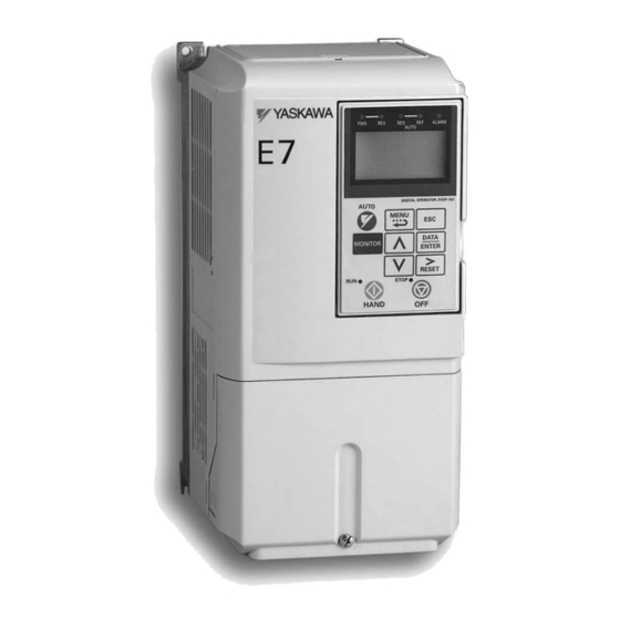
- Page 15 Component Names Models CIMR-E7U20P4 thru 2018 and 40P4 thru 4018 The external appearance, component names, and terminal arrangement of the Drive are shown in Fig 1.4. and 1.5. Top protective cover [Part of NEMA Type (IEC IP20)] Mounting hole Front cover Digital Operator Diecast Heat Sink Nameplate...
- Page 16 Models CIMR-E7U2022 thru 2110 and 4030 thru 4300 The external appearance, component names, and terminal arrangement of the Drive are shown in Fig 1.6 and 1.7. Mounting holes Mounting holes Drive cover Drive cover Cooling fan Cooling fan Front cover Front cover Digital Operator Digital Operator...
-
Page 17: Exterior And Mounting Dimensions
Exterior and Mounting Dimensions 5516 DIMENSIONS: E7 (NEMA 1) 208/240V (3.6-74.8AMPS) 480V (1.8-40AMPS) FRONT VIEW SIDE VIEW MOUNTING HOLES FOR "A" SIZE SCREW 1.38 DIA. (2) HOLES SIZE "J" .87 DIA. BOTTOM VIEW OUTPUT DIMENSIONS IN INCHES APPROX. MODEL CURRENT RATED NOMINAL WEIGHT... - Page 18 5517 DIMENSIONS: E7 (NEMA 1) 208/240V (88-115AMPS) 480V (67.2-125AMPS) MOUNTING HOLES FOR "A" SIZE SCREWS SIZE "K" HOLE (2) HOLES SIZE "L" (2) HOLES SIZE "J" OUTPUT DIMENSIONS IN INCHES APPROX. RATED MODEL CURRENT NOM. WEIGHT RATING MOUNTING INPUT CIMR-E7U (LBS.) (AMPS) 20221...
- Page 19 208-230V (162-396AMPS) 5518 DIMENSIONS: E7 (PROTECTED CHASSIS) 480V (156-304AMPS) FRONT VIEW MOUNTING HOLES FOR "A" SIZE SCREW OUTPUT DIMENSIONS IN INCHES APPROX. CURRENT RATED MODEL NOM. WEIGHT RATING MOUNTING INPUT CIMR-E7U (LBS.) (AMPS) 20370 3.94 22.64 9.84 23.62 14.96 2.56 11.73 20450 22.64...
- Page 20 5519 DIMENSIONS: E7 (PROTECTED CHASSIS) 480V (414-756AMPS) MOUNTING HOLES FOR "A" SIZE SCREWS OUTPUT DIMENSIONS IN INCHES APPROX. RATED MODEL CURRENT NOM. WEIGHT RATING MOUNTING INPUT CIMR-E7U (LBS.) (AMPS) 41850 ---- ---- 50.00 10.63 51.38 27.93 3.35 16.34 4.94 42200 350-400 50.00 10.63...
-
Page 21: Checking And Controlling Installation Site
Checking and Controlling Installation Site Install the Drive as described below and maintain optimum conditions. Installation Site Install the Drive under the following conditions in Pollution Degree 1 & 2 environments per UL Standards. This excludes wet locations where surfaces may become conductive due to moisture and contaminant loading. Table 1.3 Installation Site Specifications Type Ambient Operating Temperature... -
Page 22: Installation Orientation And Clearances
Installation Orientation and Clearances Install the Drive vertically so as not to reduce the cooling efficiency. When installing the Drive, always provide the following installation clearances to allow normal heat dissipation. Ensure that the heatsink is against a closed surface to avoid diverting cooling air around the heatsink. -
Page 23: Removing And Attaching Terminal Cover
Removing and Attaching Terminal Cover Remove the terminal cover to connect cables to the control circuit and main circuit terminals. Removing the Terminal Cover Models CIMR-E7U20P4 thru 2018 and 40P4 thru 4018 Loosen the screw at the bottom of the terminal cover, press in on the sides of the terminal cover in the directions of arrows 1, and then lift up on the terminal in the direction of arrow 2. -
Page 24: Removing/Attaching Digital Operator And Front Cover
Removing/Attaching Digital Operator and Front Cover Models CIMR-E7U20P4 thru 2018 and 40P4 thru 4018 For Models CIMR-E7U2018/4018 and smaller, remove the terminal cover and then use the following procedures to remove the Digital Operator and front cover. Removing the Digital Operator Press on the side of the Digital Operator in the direction of arrow 1 to unlock the Digital Operator and lift the Digital Operator in the direction of arrow 2 to remove the Digital Operator as shown in Fig 1.13. - Page 25 Models CIMR-E7U2022 thru 2110 and 4030 thru 4300 For Models CIMR-E7U2022/4030 and larger, remove the terminal cover and then use the following procedures to remove the Digital Operator and front cover. Removing the Digital Operator Use the same procedure for Models CIMR-E7U2018/4018 and smaller. Removing the Front Cover Loosen all screws on the front cover.
- Page 26 Mounting the Digital Operator Attach the front cover, mount the Digital Operator onto the Drive using the following procedure. 1. Hook the Digital Operator at A (two locations) on the front cover in the direction of arrow 1 as shown in the following illustration.
-
Page 27: Electrical Installation
Chapter 2 Electrical Installation This chapter describes wiring terminals, main circuit terminal connections, main circuit terminal wiring specifications, control circuit terminals, and control circuit wiring specifications. Terminal Block Configuration ..........2-2 Wiring Main Circuit Terminals..........2-3 Control Wiring ..............2-12 EMC Compatibility............2-19 Electrical Installation 2 - 1... -
Page 28: Terminal Block Configuration
Terminal Block Configuration The wiring terminals are shown in Fig 2.1, Fig 2.2 and Fig 2.3. Control circuit terminals Control circuit terminals (See Figure 2.3) Main circuit terminals Charge indicator Ground terminal Ground terminal Fig 2.1 Terminal Configuration for Models CIMR-E7U2018/4018 and smaller Control circuit terminals (See Figure 2.3) Charge indicator... -
Page 29: Wiring Main Circuit Terminals
Wiring Main Circuit Terminals Applicable Wire Sizes and Closed-loop Connectors Select the appropriate wires and crimp terminals from Table 2.1 to Table 2.2. Table 2.1 208-240Vac Wire Sizes and Connector Specifications Wire Size Recommended Clamping Range Wire Size Drive Model Terminal Torque Wire... - Page 30 Table 2.1 208-240Vac Wire Sizes and Connector Specifications Wire Size Recommended Clamping Range Wire Size Drive Model Terminal Torque Wire Terminal Symbol CIMR-E7U Screws lb. in. Type (N•m) 154.8 to 197.9 2/0 to 4/0 R/L1, S/L2, T/L3, 1 U/T1, (17.6 to 22.5) (60 to 100) (60) V/T2, W/T3, R1/L11, S1/L21, T1/L31...
- Page 31 Table 2.2 480Vac Wire Sizes and Connector Specifications Wire Size Clamping Recommended Range Drive Model Terminal Torque Wire Size AWG Terminal Symbol Wire Type CIMR-E7U Screws lb. in. (N•m) R/L1, S/L2, T/L3, 10.6 to 13.2 14 to 10 U/T1, V/T2, W/T3 40P4 (1.2 to 1.5) (2 to 5.5)
- Page 32 Table 2.2 480Vac Wire Sizes and Connector Specifications Wire Size Clamping Recommended Range Drive Model Terminal Torque Wire Size AWG Terminal Symbol Wire Type CIMR-E7U Screws lb. in. (N•m) 79.2 to 87.97 1 to 1/0 R/L1, S/L2, T/L3, 1, U/T1, V/T2, (9.0 to 10.0) (50 to 60) (50)
- Page 33 Table 2.2 480Vac Wire Sizes and Connector Specifications Wire Size Clamping Recommended Range Drive Model Terminal Torque Wire Size AWG Terminal Symbol Wire Type CIMR-E7U Screws lb. in. (N•m) R/L1, S/L2, T/L3, U/T1, V/T2, W/T3, R1/L11, S1/L21, T1/L33 4185 200/ 200, 400/ R/L1, S/L2, T/L3,...
- Page 34 Main Circuit Terminal Functions Main circuit terminal functions are summarized according to terminal symbols in Table 2.3. Wire the terminals correctly for the desired purpose. Table 2.3 Main Circuit Terminal Functions (208-240Vac and 480Vac) Model: CIMR-E7U _ _ _ _ Purpose Terminal Designation 208-240Vac...
- Page 35 (See Appendix E) may result in damage to the Drive and/or personal injury. 2. Control power is supplied internally from the main circuit DC power supply for all Drives. 3. Consult your Yaskawa representative before using 12-pulse rectification. Electrical Installation 2 - 9...
- Page 36 (See Appendix E) may result in damage to the Drive and/or personal injury. 2. Control power is supplied internally from the main circuit DC power supply for all Drives. 3. Consult your Yaskawa representative before using 12-pulse rectification. Electrical Installation 2 - 10...
- Page 37 Cable Length between Drive and Motor If the cable between the Drive and the motor is long, the high-frequency leakage current will increase, causing the Drive output current to increase as well. This may affect peripheral devices. To prevent this, reduce cable length, or if necessary, adjust the carrier frequency (set in C6-02) as shown in Table 2.6.
-
Page 38: Control Wiring
(0.5 to 2 *1.Use shielded twisted-pair cables to input an external speed command. *2.Yaskawa recommends using straight solderless terminals on digital inputs to simplify wiring and improve reliability. *3. Yaskawa recommends using a thin-slot screwdriver with a 3.5 mm blade width. - Page 39 Control Circuit Terminal Functions The factory default functions of the control circuit terminals are shown in Table 2.8. Table 2.8 Control Circuit Terminals Type Signal Name Description Signal Level Forward run/stop command Forward run when CLOSED; stopped when OFF. Reverse run/stop command Reverse run when CLOSED;...
- Page 40 DIP Switch S1 DIP Switch S1 is described in this section. The functions of DIP switch S1 are shown in Table 2.9. Terminating resistance DIP Switch S1 located on terminal board. Fig 2.6 DIP Switch S1 Location Table 2.9 DIP Switch S1 Name Function Setting...
- Page 41 Sinking/Sourcing Mode The input terminal logic can be switched between sinking mode (0V common) and sourcing mode (+24V common) by using the terminals SN, SC, and SP. An external power supply can also be connected, providing more freedom in signal input methods.
- Page 42 Terminal Connections Connections to Drive terminals are shown in Fig 2.7. DC Reactor Standard: CIMR-E7U2022 to 2110 CIMR-E7U4030 to 4300 Shorting Bar Standard: CIMR-E7U20P4 to 2018 CIMR-E7U40P4 to 4018 MCCB Motor R/L1 U/T1 3-Phase Power Supply S/L2 V/T2 50/60Hz T/L3 W/T3 Foward Run/Stop Fault Contact...
- Page 43 Control Circuit Wiring Precautions Observe the following precautions when wiring control circuits: Separate control wiring from power/motor wiring (terminals R/L1, S/L2, T/L3, U/T1, V/T2, W/T3, 2, and 3) and other high-power lines. Separate wiring for control circuit terminals MA, MB, MC, M1, M2, M3, and M4 (digital outputs) from wiring to other control circuit terminals.
- Page 44 Field Wiring Diagram Use this diagram to document field wiring. It may be helpful to copy this page based on installation needs. R/L1 U/T1 S/L2 V/T2 T/L3 W/T3 S3 (H1-01) S4 (H1-02) S5 (H1-03) (H2-01) S6 (H1-04) S7 (H1-05) (H2-02) E(G) E(G) +V +15VDC, 20mA...
-
Page 45: Emc Compatibility
Introduction This section describes the measures necessary to comply with the EMC Directive. The manual's installation and wiring instructions must be followed for compliance. Yaskawa products are tested by authorized organizations using the standards listed below. Product standard: EN 61800-3:1996 EN 61000-3-2;... - Page 46 Electromagnetic Compatibility (EMC) Recommended EMC Filters EMC Filter Drive Model Weight Dimensions CIMR-E7U Model Number Current Rating inches (mm) (kg) 208-240 Vac 20P4 2.43 5.500 x 13 x 1.875 20P7 FS5972-10-07 10 A (1.1) (141 x 330 x 46) 21P5 2.87 5.500 x 13 x 1.875 FS5972-18-07...
- Page 47 EMC Filter Drive Model Weight Dimensions CIMR-E7U Model Number Current Rating inches (mm) (kg) 4090 24.25 5.125 x 24 x 9.4375 FS5972-250-37 250 A (11) (130 x 610 x 240) 4110 Ground clip Ground plate Fig 2.10 Grounding Surface Layout The grounding surfaces must be highly conductive bare metal.
- Page 48 Grounding Remove varnish or paint Metal plate E7 Drive Filter Cable length Maximum of 15.75” Motor cable Length Maximum of 82 feet Grounding Remove varnish or paint Fig 2.11 EMC Filter Layout Electrical Installation 2 - 22...
-
Page 49: Digital Operator
Chapter 3 Digital Operator This chapter describes the displays and functions of the Digital Operator. Digital Operator Display............3-2 Digital Operator Keys ............3-3 Drive Mode Indicators............3-4 Drive Main Menus..............3-7 Main Menu Structure ............3-8 Operation Menu ..............3-9 Quick Setting Menu ............3-12 Programming Menu ............3-13 Modified Constants Menu ..........3-14 Auto-Tuning Menu .............3-14 Example of Changing a Parameter ........3-15... -
Page 50: Digital Operator Display
Digital Operator The Digital Operator is used for programming, operating, and monitoring drive operation. The E7 Drive will not run unless the digital operator is securely attached to the Drive. Digital Operator Display The various items included on the Digital Operator are described below. -
Page 51: Digital Operator Keys
Digital Operator Keys The names and functions of the Digital Operator Keys are described in Table 3.1. Table 3.1 Digital Operator Keys Name Function • Pressing the AUTO key will put the Drive in the “Auto” mode. • In the “Auto” mode, the Drive will be capable of starting/stopping depending on the setting of parameter “b1-02”... -
Page 52: Drive Mode Indicators
Table 3.1 Digital Operator Keys Name Function • Pressing the HAND key will put the Drive in the “Hand” mode and start the Drive. • In the “Hand” mode, the drive speed command will depend on the setting of parameter “b1-11” (Hand Frequency Reference Selection). HAND Key •... - Page 53 AUTO Sequence (SEQ) Indicator The status of the AUTO “Sequence” (SEQ) indicator is shown in Table 3.3. This indicator is always “Off” when the Drive is in the “Hand” mode. When the Drive is in the “Auto” mode, the SEQ indicator status is dependent on the setting of parameter “b1-02”...
- Page 54 Run Indicator The status of the “RUN” indicator is shown in Table 3.5 when the Drive is in either the “Hand” or “Auto” mode. Table 3.5 RUN Indicator Indicator Status Condition Drive is running Blinking Drive is decelerating to a stop Drive is stopped Stop Indicator The status of the “STOP”...
-
Page 55: Drive Menus
Drive Main Menus The Drive’s parameters and monitoring functions are organized into groups called menus that make it easier to read and set parameters. The Drive is equipped with five menus. The five menus and their primary functions are shown in Table 3.7. Table 3.7 Drive Main Menus Main Menu Primary Function(s) -
Page 56: Main Menu Structure
Main Menu Structure The menu selection display will appear when the MENU key is pressed from a monitor or setting display. While viewing the menu selection display, press the MENU key repeatedly to scroll between the menu selections. -DRIVE- ** Main Menu ** - - - - - - - - - - - - - - Operation -DRIVE-... -
Page 57: Operation Menu
Operation Menu This menu is used for setting a speed command or monitoring values such as output frequency and output current. It is also used for displaying the fault history and the fault traces. The Drive must be in this menu in order to run. U1 Monitor List Follow the key operations below to access the Operation Menu: -DRIVE-... - Page 58 U2 Fault Trace List After viewing the “Monitor” parameter list, in order to view the “Fault Trace” parameter list, follow the key operations below: -DRIVE- -DRIVE- -DRIVE- Monitor Fault Trace Current Fault -01= 0.00Hz U2-01= None U2-01 None - - - - - - - - - - - - - - - - - - - - - - - - - - - - - - - - - - - - - - - - - - - - - - - - - - - - - - - - - - - - U1-02=...
- Page 59 U3 Fault History List After viewing the “Fault Trace” parameter list, in order to view the “Fault History” parameter list, follow the key operations below: -DRIVE- -DRIVE- -DRIVE- Fault Trace Fault History Last Fault U2-01= None U3-01= None U3-01= None - - - - - - - - - - - - - - - - - - - - - - - - - - - - - - - - - - - - - - - - - - - - - - - - - - - - - - - - - - - -...
-
Page 60: Quick Setting Menu
Quick Setting Menu This menu is used to set/read the most commonly used parameters in the Drive. Follow the key operations below to access the Quick Setting Menu: -QUICK- -QUICK- Reference Source ** Main Menu ** - - - - - - - - - - - - - - - - - - - - - - - - - - - - - - - - - - B1-01= Quick Setting... -
Page 61: Programming Menu
Programming Menu This menu is used to set/read every parameter in the Drive. Follow the key operations below to access the Programming Menu. -ADV- -ADV- Initialization ** Main Menu ** - - - - - - - - - - - - - - - - - - - - - - - - - - - - - - - - - - A1-00= Programming... -
Page 62: Modified Constants Menu
Modified Constants Menu This menu is used to set/read the parameters that have been modified from their original factory default settings. Follow the key operations below to access the Modified Constants Menu. -VERIFY- ** Main Menu ** See Note 1 See Note 1 - - - - - - - - - - - - - - Modified Consts... -
Page 63: Example Of Changing A Parameter
Example of Changing a Parameter Table 3.8 provides an example of how to change parameter “C1-02” (Deceleration Time 1) from 30 seconds to 40 seconds. Table 3.14 Changing a Parameter in the Programming Menu Step Digital Operator Display Description Number -DRIVE- Frequency Ref The Drive is first powered up. - Page 64 Table 3.8 Changing a Parameter in the Programming Menu Step Digital Operator Display Description Number -ADV- Decel Time 1 Press the INCREASE key to display C1-02 (Decel Time 1). - - - - - - - - - - - - - - - - - - - - C1-02= 30.0sec (0.0~6000.0)
-
Page 65: Start Up
Chapter 4 Start Up This chapter describes the procedures to prepare the Drive for start up and the procedures to conduct a Drive start up. Drive Start Up Preparation ..........4-2 Drive Start Up Procedures ..........4-5 Start Up 4 - 1... - Page 66 1. The Drive is thoroughly tested at the factory. The start up person should verify that the drive is free of shipping and installation damage. Shipping damage is not covered by the Yaskawa warranty. Claims must be filed with the ship- ping company as soon as possible for any potential recovery via insurance.
- Page 67 If lead length must exceed this distance, reduce the carrier frequency (See Table 2.6) and consult Yaskawa toll free at 1-800-YASKAWA (927-5292) for proper installation procedures. 14. Signal and control leads must be separated from main circuit leads (R/L1, S/L2, T/L3, U/T1, V/T2, W/T3).
- Page 68 23. Wire all necessary power leads to the Drive. DO NOT CONNECT DRIVE TO MOTOR YET. 24. Wire all necessary ground wires to the Drive. 25. Wire all necessary control wires to the Drive. 26. Ensure that the power leads are connected to the R/L1, S/L2 and T/L3 terminals in the Drive. 27.
-
Page 69: Drive Start Up Procedures
DRIVE START UP PROCEDURES Please review “Drive Start Up Preparation” on page 4-2. Step 1. Confirm that all three phases are present and that the input voltage is correct for the Drive being set up. Measure the voltage on the top side of the MCCB/disconnect and record below. Table 4.1 Input Voltage Check Measurement Location Voltage (Vac) - Page 70 Press the 扶 key once to display E2-01 “Motor Rated FLA”. This parameter is the foundation of motor protection. It can be set automatically when auto-tuning is performed. Set this parameter according to the motor rated current (FLA). Press the DATA/ENTER once. Use the 扶 , ▼ , and 斧 keys to adjust E2-01 to the motor rated full load amps.
- Page 71 12. Press the 扶 key twice to display b1-03 “Stopping Method”. This parameter selects the stopping method used when a stop command is given to the Drive. Fig 4.5 Stopping Method Selection Parameter Parameter Name Setting Setting Choices Factory Setting Menu Location Digital Operator Display Range...
- Page 72 18. Press the MONITOR key to display the U1 monitors. Use the 扶 and ▼ keys to view Output Current (U1-03), Output Voltage (U1-06), and DC Bus Voltage (U1-07) while running the Drive throughout its entire speed range. Record the following information at each speed: Frequency Output Current Output Voltage...
- Page 73 21. Check the signal for proper polarity. Observe if the speed command can achieve the minimum and maximum speeds desired. If not, perform the following: For 0-10Vdc input (Terminal A1) With no input, adjust Bias (H3-03 setting) until an output of “0.0 Hz” is obtained. With full-scale input, adjust Gain (H3-02 setting) until an output of “60.0 Hz”...
- Page 74 Notes: Start Up 4 - 10...
-
Page 75: Basic Programming
Chapter 5 Basic Programming This chapter describes basic programming for the Drive. Basic Programming Parameters..........5-2 Language Selection.............5-2 Speed Command Source Selection........5-2 Run Command Source Selection ........5-3 Stopping Method Selection..........5-5 Reverse Operation Selection..........5-6 Drive Delay ................5-7 PI Function ................5-8 Energy Savings ..............5-14 Accel/Decel Time Settings..........5-14 Speed Command Limits ............5-15 Input Voltage Setting ............5-15... -
Page 76: Basic Programming Parameters
E7 Basic Programming Parameters Language Selection A1-00 Select Language The setting of parameter A1-00 determines which international language the Drive will display non-numerical text. The A1-00 parameter will not be changed by either an Initialization of the drive (A1-03=1110, 2220, or 3330) or a change in the setting of o2-09 (Initialization Mode Selection). -
Page 77: Run Command Source Selection
To use LONWorks to input a speed command: Set b1-01=3 and plug a LONWorks option board into the 2CN port on the Drive Control PCB. Consult the manual supplied with the option board for instructions on integrating the Drive into the LONWorks System. - Page 78 3-Wire When any of the multi-function digital input parameters, H1-01 through H1-05, is set to 0, terminals S1 and S2 become Run and Stop, respectively. The multi-function digital input that was set to 0 will function as a Forward/Reverse input for the Drive. When the Forward/Reverse input is open, the Drive will run in the Forward direction and when the input is closed, the Drive will run in the Reverse direction.
-
Page 79: Stopping Method Selection
Stopping Method Selection b1-03 Stopping Method There are four methods of stopping the Drive when the RUN command is removed. 0: Ramp to stop: When the run command is removed, the Drive will decelerate the motor to 0 rpm. The rate of deceleration is determined by the active deceleration time. -
Page 80: Reverse Operation Selection
The level of DC Injection current is set by parameter b2-02. The length of time that DC current is injected into the motor windings is determined by the set value in b2-04 and the output frequency at the time the run command is removed. Run Command b2-04 x 10 b2-04... -
Page 81: Drive Delay
Drive Delay b1-11 Drive Delay Time Setting The Drive will delay any run command from executing until the b1-11 time has expired. During the drive delay time, the digital operator will display: DDLY Waiting to RUN Both the ALARM and RUN indicators will blink while the Drive waits to execute the run command. Basic Programming 5 - 7... -
Page 82: Pi Function
PI Function The capability to accept an analog signal as feedback for a PI (Proportional – Integral) control function is built into the Drive. Frequency Reference / PI Setpoint Frequency Reference / PI Target D1-04 Frequency Reference using multi-step Sleep function command selection b5-21 D1-02... - Page 83 In some situations there is no setpoint but rather two feedback inputs. The drive can be programmed to maintain a set differential between two analog signals. If input A2 is configured as a “PI Differential” (H3-09=16), then the Drive will attempt to maintain a set difference between the measurements read on inputs A1 and A2.
- Page 84 b5-07 PI Offset Adjustment Every time the PI output is updated, the PI offset is summed with the PI output. If the Drive is configured for Differential PI Regulation (H3-09=16), then the PI Offset is the targeted maintained differential between the signal measured on analog input A1 and the signal measured on analog input A2.
- Page 85 b5-15 Sleep Function Start Level b5-16 Sleep Delay Time b5-21 Sleep Input Source The Sleep Function prevents the Drive from running when the PI loop output or the speed command is so low that no usable work is being done and equipment damage may result, the Sleep Function. If the Drive’s output drops below the level set by PI Sleep Function Start Level (b5-15) and remains there at least as long as the delay time determined by the PI Sleep Delay Time (b5-16), then the Drive’s internal run command drops out and the Drive output ceases.
- Page 86 The setting of parameter b5-21 determines whether the PI Sleep Function Start Level (b5-15) is compared to the speed com- mand as determined by b1-01 (b5-21=0), the output of the PI function summed with the Speed Command (b5-21=1), or not used at all (b5-21=2).
- Page 87 X X X X X Digit 5 Digit 4 Digit 3 Digit 2 Digit 1 Digits 1 through 4 set the desired number to be displayed at 100% speed. Digit 5 determines the number of decimal places If Digit 5 =0 number format is XXXX If Digit 5 = 1 number format is XXX.X If Digit 5 = 2 number format is XX.XX...
-
Page 88: Energy Savings
b5-27 PI Snooze Feedback Level This is a second method of initiating the Snooze Function. If the PI feedback level exceeds the PI Snooze Feedback Level (b5- 27), then the Drive output shuts off. Once the PI feedback drops below the PI Snooze Deactivation Level (b5-24) then normal Drive and PI operation return. -
Page 89: Speed Command Limits
Output frequency Acceleration/ deceleration time switching frequency (C1-11) C1-03 rate C1-01 rate C1-02 rate C1-04 rate When output frequency ≥ C1-11, acceleration and deceleration are performed using Acceleration/deceleration Time 1 (C1-01, C1-02). When output frequency < C1-11, acceleration and deceleration are performed using Acceleration/deceleration Time 2 (C1-03, C1-04). -
Page 90: Motor Rated Current Setting
Motor Rated Current Setting E2-01 Motor Rated Current The Motor Rated Current parameter (E2-01) is necessary information used by the Drive to help protect the motor. The motor protection parameter is L1-01 and must be enabled. Set E2-01 to the full load amps (FLA) stamped on the motor’s nameplate. During Auto-tuning, the motor rated current (T1-04) must be entered in the Auto-tuning menu. -
Page 91: Momentary Power Loss Function
H3-02 = 100% H3-02 = 100% 200% H3-02 = 100% H3-02 = 200% Output Output Output Output Frequency Frequency Frequency Frequency H3-03 = 0% H3-03 = 0% H3-03 = 0% H3-03 = 0% 20mA 20mA 20mA 20mA After Gain Applied Before Gain Applied Fig 5.14 Terminal A1 and A2 Analog Inputs Gain Adjustment Example H3-10 Terminal A2 Gain Setting... -
Page 92: Speed Command Loss Detection
If L2-01=1, the Drive restarts without the UV1 fault if power is returned within the time specified in L2-02, the Momentary Power Loss Ride-thru Time. During the power loss but before the fault trip, the digital operator will display a UV alarm. If L2-02 is set for a time longer than the control power supply can be sustained, a UV1 fault will not occur and the Drive restarts upon the return of AC power. -
Page 93: Torque Detection
overvoltage fault trying each successful try but failed L5-03 seconds successful L2-03 L2-03 L2-03 attempts count OC condition Drive trips on OC, voltage gone, resets (3) resets (2) and tries remains high and runs. again but motor still for a long time, shorted, trips again. - Page 94 To configure Torque Detection requires the following decisions: Do you wish to check for an overtorque condition or an undertorque condition? Do you wish to check for the torque condition whenever the Drive is running or only at speed agree? Nuisance detection during acceleration, when high torques are normally required, can be avoided by using Torque Detection only at Speed Agree.
-
Page 95: Cooling Fan Operation
Motor current (output torque) L6-02 or L6-05 L6-03 L6-03 Undertorque detection 1 NO or Undertorque detection 2 NO L6-06 L6-06 * The undertorque detection disabled margin is approximately 10% of the Inverter rated output current (or motor rated torque) Fig 5.19 Under Torque Detection Timing Chart Cooling Fan Operation L8-11 Heatsink Cooling Fan Operation Delay Time... -
Page 96: User Initialization
For example, to display the Flash ID as the Power-On monitor, then o1-01 must be set to “14” and o1-02 must be set to “4”. The next time Drive power is cycled, the digital operator displays U1-14, U1-15, and U1-16. -DRIVE- Active Monitor Title Active Monitor... -
Page 97: Elapsed Timer Function
in order to access the Speed Command function. This is not to be confused with pressing the ENTER key to achieve a change in speed, which is the subject of parameter o2-05. Elapsed Timer Function o2-08 Cumulative Operation Time Selection The Drive features an Elapsed Timer function. - Page 98 -ADV- READ INV→OP READ A successful READ of the parameter values will display: -ADV- READ READ COMPLETE An error may occur while saving the parameter values to memory. If an error is displayed, press any key to cancel the error display and return to parameter o3-01.
- Page 99 The digital operator will not display which parameters did not match, only that the verification found discrepancies in some parame- ter values. Yaskawa Electric America offers DriveWizard™ software that can also READ, COPY, and Verify Drive parameter values. DriveWizard™ lists all discrepancies between the Drive and a pre-saved parameter file when verifying is performed.
-
Page 100: Auto Tuning
Auto-Tuning T1-02 Motor Rated Power T1-04 Motor Rated Current The Drive requires Line-To-Line Resistance auto-tuning before it can properly perform the Estimated Speed Search method. This type of motor auto-tuning allows for bi-directional speed search. The T1 parameters are found under the Auto-Tuning menu. -
Page 101: Diagnostic & Troubleshooting
Chapter 6 Diagnostics & Troubleshooting This chapter describes diagnostics and troubleshooting for the Drive. Fault Detection ..............6-2 Alarm Detection ..............6-8 OPE Errors ................ 6-11 Auto-Tuning Faults ............6-12 Digital Operator Copy Function Faults.......6-13 Troubleshooting ..............6-14 Main Circuit Test Procedure ..........6-20 Drive Date Stamp Information ...........6-24 Diagnostic &... -
Page 102: Fault Detection
Fault Detection When the Drive detects a fault, fault information is displayed on the digital operator, the fault contact closes, and then the motor coasts to stop. (However, a fault that selects a stopping method will operate according to the stopping method.) •... - Page 103 Table 6.1 Fault Displays and Processing Digital Description Cause Corrective Action Operator Display Perform a factory initialization Cycle power off and on to the Noise or spike on the control CPF05 CPU External A/D Converter Fault External A/D Err Drive circuit input terminals Replace the control board Cycle power off and on to the...
- Page 104 Table 6.1 Fault Displays and Processing Digital Description Cause Corrective Action Operator Display Remove power to the Drive Connect the option board once more An option board is not correctly connected to the con- Perform a factory initialization Communication Option Card CPF23 trol board or an option board Interconnection Fault...
- Page 105 Table 6.1 Fault Displays and Processing Digital Description Cause Corrective Action Operator Display Remove the motor and run the Drive without the motor Shorted Drive output phase to phase, shorted motor, locked Check the motor for a phase-to- rotor, load too heavy, accel/ phase short Overcurrent decel time too short, contactor...
- Page 106 Table 6.1 Fault Displays and Processing Digital Description Cause Corrective Action Operator Display Ensure the values in L6-02 and Overtorque Detection 1 L6-03 are appropriate Drive output current > L6-02 for more than Motor is overloaded Overtorque Det 1 Check application/machine the time set in L6-03 status to eliminate fault Attach the digital operator...
- Page 107 Table 6.1 Fault Displays and Processing Digital Description Cause Corrective Action Operator Display Cycle power off and on to the Drive Shorted dynamic braking Dynamic Braking Transistor transistor, high DC bus Replace defective dynamic DynBrk Transistr voltage, defective dynamic The dynamic braking transistor failed braking transistor or resistor braking resistor Monitor DC bus voltage...
-
Page 108: Alarm Detection
Alarm Detection Alarms are detected as a type of Drive protection function that do not operate the fault contact. The Drive will automatically return to its original status once the cause of the alarm has been removed. The Digital Operator display flashes and the alarm is output at the multi-function outputs (H2-01 to H2-02). When an alarm occurs, take appropriate countermeasures according to the table below. - Page 109 Table 6.2 Alarm Displays and Processing Digital Description Cause Corrective Action Operator Display Verify Drive is programmed to receive the PI Feedback source signal Check to ensure the PI Feedback source is installed and working PI Feedback Loss properly PI Feedback source This fault occurs when PI Feedback Loss Check the motor for a phase-to- Detection is programmed to fault...
- Page 110 Table 6.2 Alarm Displays and Processing Digital Description Cause Corrective Action Operator Display Ensure the values in L6-02 and L6-03 are appropriate Undertorque Detection 1 Undertorq Det 1 Drive output current < L6-02 for more than Motor is underloaded (Flashing) Check application/machine status the time set in L6-03 to eliminate fault...
- Page 111 Operator Programming Errors (OPE) An Operator Programming Error (OPE) occurs when an inapplicable parameter is set or an individual parameter setting is inappropriate. The Drive does not operate until the parameter is set correctly. (Alarm output and fault contact do not operate.) If an OPE occurs, change a parameter by checking the cause shown in Table 6.3.
-
Page 112: Auto-Tuning Faults
Auto-Tuning Faults Auto-tuning faults are shown below. When the following faults are detected, the fault is displayed on the digital operator and the motor coasts to a stop during operation. The fault contact is not activated. Table 6.4 Auto-Tuning Displays and Processing Digital Operator Display Probable Cause Corrective Action... -
Page 113: Digital Operator Copy Function Faults
Digital Operator COPY Function Faults These faults can occur occurred during the operator COPY function. Fault content is displayed on the operator. An error during the COPY function application does not activate the fault contact output or alarm output. Table 6.5 Digital Operator COPY Function Faults Function Digital Operator Display Probable Causes... -
Page 114: Troubleshooting
Troubleshooting Due to parameter setting errors, faulty wiring, etc., the Drive and motor may not operate as expected when the system is started up. If this occurs, use this section as a reference and apply the appropriate measures. If a fault is displayed on the digital operator, refer to Fault Detection, Table 6.1. If Parameter Cannot Be Set Use the following information if a Drive parameter cannot be set. - Page 115 If the Motor Does Not Operate Use the following information if the motor does not operate. Ensure the digital operator is securely connected to the Drive. The motor does not operate when the HAND key on the Digital Operator is pressed. The following causes are possible: The Speed Command is too low.
- Page 116 The motor stops during acceleration or when a load is connected. The load may be too heavy. The Drive has a stall prevention function and an automatic torque boost function, but the motor responsiveness limit may be exceeded if acceleration is too rapid or if the load is too heavy. Lengthen the acceleration time (CI-01) or reduce the load.
- Page 117 If the Motor Overheats Take the following steps if the motor overheats. The load is too heavy. If the motor load is too heavy and the motor is used when the effective torque exceeds the motor's rated torque, the motor will overheat.
- Page 118 If the Ground Fault Interrupter Operates When the Drive is Run The Drive performs internal switching, so there is a certain amount of leakage current. This may cause the ground fault interrupter to operate and cut off the power supply. Change to a ground fault interrupter with a high leakage detection level (i.e., a sensitivity current of 200 mA or greater per Unit, with an operating time of 0.1 s or more), or one that incorporates high frequency countermeasures (i.e., one designed for use with Drives).
- Page 119 If the Motor Rotates Even When Drive Output is Stopped If the motor rotates even when the Drive is stopped, the DC injection braking may be insufficient. If the motor continues operating at low speed, without completely stopping after a stop has been executed, it means that the DC injection braking is not decelerating the motor enough.
-
Page 120: Main Circuit Test Procedure
Main Circuit Test Procedure Before attempting any troubleshooting checks, make sure that the three-phase power is disconnected and locked out. With power removed from the unit, the DC bus capacitors will stay charged for several minutes. The Charge LED in the Drive will glow red until the DC bus voltage is below 10Vdc. - Page 121 Table 6.6 Main Circuit Test Procedure Check Procedure (Continued from previous page) 11. Place the positive (red) meter lead on terminal ⊕ 1. Place the negative (black) meter lead on terminal R/L1. Expected reading is OL displayed. Input Diodes 12. Place the positive (red) meter lead on terminal ⊕ 1. (D1-D12 or Q1) Place the negative (black) meter lead on terminal S/L2.
- Page 122 Table 6.6 Main Circuit Test Procedure Check Procedure The output transistors are used to switch the DC bus voltage to allow current to flow to the motor. 1. Set a digital multi-meter to the Diode Check setting. 2. Place the positive (red) meter lead on terminal U/T1. Place the negative (black) meter lead on terminal ⊕...
- Page 123 Table 6.6 Main Circuit Test Procedure Check Procedure The Heat Sink & Internal Cooling Fans cool the heat sink as well as the output transistor mod- ules of the Drive. 1. Conduct a visual inspection to ensure the fan turns freely. 2.
-
Page 124: Drive Date Stamp Information
Drive Date Stamp Information This information is used to determine when a Drive was built to see if it is within its warranty period. The date stamp is located on the lower right side of the Drive. Fig 6.1 Date Stamp Location YEA Production Manufacture Date 00.7.22... -
Page 125: Maintenance
Chapter 7 Maintenance This chapter describes basic maintenance and inspection of the Drive. Please refer to these instructions to ensure that your Drive receives the proper maintenance to maintain overall performance. Periodic Inspection ..............7-2 Preventive Maintenance ............7-3 Periodic Maintenance of Parts..........7-4 Cooling Fan Replacement ..........7-5 Removing and Mounting the Terminal Card ......7-7 Maintenance 7 - 1... -
Page 126: Periodic Inspection
Periodic Inspection Check the following items during periodic maintenance. The motor should not be vibrating or making unusual noises. • There should be no abnormal heat generation from the Drive or motor. • The ambient temperature should be within the Drive specification of -10°C to 40°C (14°F to 104°F). •... -
Page 127: Preventative Maintenance
Preventive Maintenance Table 7.3 Preventive Maintenance Inspection Points Item Check Points Every 3-6 Months Yearly Ambient Temperature Humidity Environment Dust Harmful Gas General Oil Mist Equipment Abnormal vibration or noise AC Power Supply Main circuit & control voltage Loose lugs, screws & wires Hot spots on parts Corrosion Conductors &... -
Page 128: Periodic Maintenance Of Parts
Periodic Maintenance of Parts In order to keep the Drive operating normally over a long period of time, it is necessary to perform periodic inspections and replace parts according to their service life. Periodic inspection standards vary depending the Drive's installation environment and usage conditions. The Drive's maintenance periods are noted below. -
Page 129: Cooling Fan Replacement
Heatsink Cooling Fan Replacement Models CIMR-E720P4 thru 2018 and 40P4 thru 4018 A cooling fan is attached to the bottom of the Drive. If the Drive is installed using the mounting holes on the back of the Drive, the cooling fan can be replaced without removing the Drive from the installation panel. - Page 130 Models CIMR-E72022 thru 2010 and 4030 thru 4300 A cooling fan assembly is attached to the top inside the Drive. The cooling fan assembly includes the heat sink cooling fans and the internal cooling fan. The cooling fan(s) can be replaced without removing the Drive from the installation panel. Removing the Cooling Fan Assembly Always turn OFF the input power before removing and installing the heatsink cooling fan assembly.
-
Page 131: Removing And Mounting The Terminal Card
Removing and Mounting the Terminal Card The terminal card can be removed and mounted without disconnecting the control wiring. Always confirm that input power is removed and the Charge LED is not lit before removing or mounting the IMPORTANT terminal card. Removing the Terminal Card 1. - Page 132 Notes: Maintenance 7 - 8...
-
Page 133: Appendix A Parameter List
Appendix A Parameter List This appendix lists all the parameter numbers and names, along with a description of each. Also, below the parameter name in bold type is the abbreviated name as it appears on the digital operator display/keypad. User Parameter ..............A-2 Monitor Display .............. - Page 134 Table 1: E7 Parameter List Parameter Parameter Name Setting Factory Menu Description Range Setting Location Digital Operator Display Initialization Language selection for digital operator display 0: English 1: Japanese 2: Deutsch A1-00 Language Selection 0 to 6 Quick Setting 3: Francais Select Language 4: Italiano 5: Espanol...
- Page 135 Table 1: E7 Parameter List (Continued) Parameter Setting Factory Menu Parameter Name Description Range Setting Location Digital Operator Display User Parameter 7 – A2-07 Programming User Param 7 User Parameter 8 – A2-08 Programming User Param 8 User Parameter 9 –...
- Page 136 Table 1: E7 Parameter List (Continued) Parameter Setting Factory Menu Parameter Name Description Range Setting Location Digital Operator Display Sequence Selects the speed command input source. 0: Operator - Digital preset speed d1-01 Frequency Reference 1: Terminals - Analog Input Terminal A1 (or Terminal A2 see Quick Setting b1-01 Selection...
- Page 137 Table 1: E7 Parameter List (Continued) Parameter Setting Factory Menu Parameter Name Description Range Setting Location Digital Operator Display Speed Search Enables/disables and selects the speed search function at start. 0: SpdsrchF Disable - Speed search at start is disabled (estimated speed method is used at other times) 1: SpdsrchF Enable - Speed search is enabled (estimated speed method)
- Page 138 Table 1: E7 Parameter List (Continued) Parameter Setting Factory Menu Parameter Name Description Range Setting Location Digital Operator Display PI Feedback Loss Detection Sets the PI feedback loss detection level as a percentage of b5-13 Level 0 to 100 Quick Setting maximum frequency (E1-04).
- Page 139 Table 1: E7 Parameter List (Continued) Parameter Setting Factory Menu Parameter Name Description Range Setting Location Digital Operator Display Energy Saving Energy Saving Control Energy Savings function enable/disable selection b8-01 Selection 0: Disabled 0 or 1 Quick Setting Energy Save Sel 1: Enabled Energy Saving Coefficient 0.0 to...
- Page 140 Table 1: E7 Parameter List (Continued) Parameter Setting Factory Menu Parameter Name Description Range Setting Location Digital Operator Display Torque Comp This parameter helps to produce better starting torque. It C4-01 Torque Compensation Gain determines the amount of torque or voltage boost based upon 0.00 to 2.50 1.00 Programming...
- Page 141 Table 1: E7 Parameter List (Continued) Parameter Setting Factory Menu Parameter Name Description Range Setting Location Digital Operator Display Reference Limits Determines maximum speed command, set as a percentage of Frequency Reference Upper parameter E1-04. If speed command is above this value, actual d2-01 Limit 0.0 to 110.0...
- Page 142 Table 1: E7 Parameter List (Continued) Parameter Setting Factory Menu Parameter Name Description Range Setting Location Digital Operator Display V/F Pattern 155 to 255.0 240V Input Voltage Setting (240V) E1-01 Set to the nominal voltage of the incoming line. Quick Setting Input Voltage 310 to 510.0 480V...
- Page 143 Table 1: E7 Parameter List (Continued) Parameter Setting Factory Menu Parameter Name Description Range Setting Location Digital Operator Display Motor Setup Motor Rated Current E2-01 Set to the motor nameplate full load amps. Quick Setting Motor Rated FLA Dependant Dependant E2-03 No-Load Current Sets the magnetizing current of the motor.
- Page 144 Table 1: E7 Parameter List (Continued) Parameter Setting Factory Menu Parameter Name Description Range Setting Location Digital Operator Display Digital Inputs 0: 3-wire control FWD/REV selection for 3-wire sequence 1: Local/Remote Sel Hand/Auto Selection - Closed = Hand, Open = Auto 2: Option/Inv Sel Selects source of speed command and sequence Closed = Option Card, Open = b1-01 &...
- Page 145 Table 1: E7 Parameter List (Continued) Parameter Setting Factory Menu Parameter Name Description Range Setting Location Digital Operator Display 12: Forward Jog Closed = drive runs forward at speed command entered into parameter d1-17. 13: Reverse Jog Closed = drive runs in reverse at speed command entered into parameter d1-17.
- Page 146 Table 1: E7 Parameter List (Continued) Parameter Setting Factory Menu Parameter Name Description Range Setting Location Digital Operator Display Digital Inputs 1E: Ref Sample Hold Analog speed command is sampled then held at time of input closure. 20: External fault, Normally Open, Always Detected, Ramp To Stop 21: External fault, Normally Closed, Always Detected, Ramp To Stop...
- Page 147 Table 1: E7 User Parameter List (Continued) Parameter Name Parameter Setting Factory Menu Description Digital Operator Range Setting Location Display Digital Outputs 0: During RUN 1 = Closed when a run command is input or the drive is outputting voltage. 1: Zero Speed = Closed when drive output frequency is less than Fmin (E1-09) 2: Fref/Fout Agree 1 = Closed when drive output speed...
- Page 148 Table 1: E7 Parameter List (Continued) Parameter Parameter Name Setting Factory Menu Description Range Setting Location Digital Operator Display Analog Inputs H3-02 Terminal A1 Gain Setting Sets the speed command when 10V is input, as a 0.0 to 100.0% Quick Setting Terminal A1 Gain percentage of the maximum output frequency (E1-04).
- Page 149 Table 1: E7 Parameter List (Continued Parameter Setting Factory Menu Parameter Name Description Range Setting Location Digital Operator Display Analog Outputs Selects which monitor will be output on terminals FM and FC. 1: Frequency Ref (100% = max. output frequency) 2: Output Freq (100% = max.
- Page 150 Table 1: E7 Parameter List (Continued Parameter Setting Factory Menu Parameter Name Description Range Setting Location Digital Operator Display Analog Outputs H4-06 Terminal AM Bias Setting Sets terminal AM output voltage (in percent of 10V) –110.0 to 0.0% Programming Terminal AM Bias when selected monitor is at 0% output.
- Page 151 Table 1: E7 Parameter List (Continued Parameter Setting Factory Menu Parameter Name Description Range Setting Location Digital Operator Display Motor Overload Enables or disables the motor thermal overload Motor Overload Protection protection. L1-01 Selection 0 to 1 Programming 0: Disabled MOL Fault Select 1: Std Fan Cooled (Enabled) Determines how much time will elapse prior to a motor...
- Page 152 Table 1: E7 Parameter List (Continued Parameter Setting Factory Menu Parameter Name Description Range Setting Location Digital Operator Display Stall Prevention 0: Disabled (Motor accelerates at active acceleration, C1-01 or C1-03. The motor may stall if load is too heavy or accel time is too short.) 1: General Purpose (When output current exceeds L3- Stall Prevention Selection During 02 level, acceleration stops.
- Page 153 Table 1: E7 Parameter List (Continued Parameter Setting Factory Menu Parameter Name Description Range Setting Location Digital Operator Display Ref Detection Speed Agreement Detection Level L4-01 0.0 to 200.0 0.0Hz Programming Spd Agree Level L4-01 and L4-02 are used in conjunction with the multi-function outputs, (H2-01and H2-02) as a setpoint Speed Agreement Detection and hysteresis for a contact closure.
- Page 154 Table 1: E7 Parameter List (Continued Parameter Setting Factory Menu Parameter Name Description Range Setting Location Digital Operator Display Hdwe Protection Internal Dynamic Braking Resis- 0: Not Provided L8-01 tor Protection Selection 0 or 1 Programming 1: Provided DB Resistor Prot When the cooling fin temperature exceeds the value set Overheat Pre-Alarm Level 50 to 130...
- Page 155 Table 1: E7 Parameter List (Continued Parameter Setting Factory Menu Parameter Name Description Range Setting Location Digital Operator Display Hunting Prev 0: Disabled (Hunting prevention function disabled.) 1: Enabled (Hunting prevention function enabled.) Hunting Prevention Selection n1-01 If the motor vibrates while lightly loaded, hunting 0 or 1 Programming Hunt Prev Select...
- Page 156 Table 1: E7 Parameter List (Continued Parameter Setting Factory Menu Parameter Name Description Range Setting Location Digital Operator Display Set Value Description LCD display becomes dark. LCD Brightness Adjustment o1-05 0 to 5 Quick Setting LCD Contrast Standard setting LCD display becomes light. Selects the "U1"...
- Page 157 Table 1: E7 Parameter List (Continued Parameter Setting Factory Menu Parameter Name Description Range Setting Location Digital Operator Display Sets how time is accumulated for the elapsed timer (o2-07). Cumulative Operation Time 0: Power-On Time (Time accumulates whenever drive o2-08 Selection 0 or 1 Quick Setting...
- Page 158 Table 2: E7 Monitor List Parameter Parameter Name Description Digital Operator Display Monitor Frequency reference (speed command) monitor when in auto Frequency Reference U1-01 mode, frequency reference (speed command) setting location Frequency Ref when in hand mode. Units changeable via o1-03. Output Frequency Output frequency (speed) monitor.
- Page 159 Table 2: E7 Monitor List (Continued) Parameter Parameter Name Description Digital Operator Display Monitor Cumulative Operation Time U1-13 Displays total operating or power-on time of the Drive. Elapsed Time Software Number U1-14 Displays Drive's software number. FLASH ID Terminal A1 Input Voltage Displays the input voltage on Terminal A1, as a percentage of U1-15 Term A1 Level...
- Page 160 Table 3: E7 Fault Trace List Fault Trace Current Fault U2-01 Current Fault Previous Fault U2-02 Last Fault Frequency Reference at Most Recent Fault U2-03 Frequency Ref Output Frequency at Most Recent Fault U2-04 Output Freq Output Current at Most Recent Fault U2-05 Output Current Output Voltage at Most Recent Fault...
- Page 161 Table 4: E7 Fault History List Fault Trace Most Recent Fault U3-01 Last Fault Most Recent Fault U3-02 Fault Message 2 Most Recent Fault U3-03 Fault Message 3 Most Recent Fault U3-04 Fault Message 4 Cumulative Operation Time at Most Recent Fault U3-05 Elapsed Time 1 Cumulative Operation Time at 2...
- Page 162 Notes: Parameter List A - 30...
-
Page 163: Appendix B - Capacity Related Parameters
Appendix B Capacity Related Parameters This appendix lists the parameters affected by the Drive Capacity setting of o2-04. Drive Capacity Selection............. B-2 Parameters Affected by Drive Capacity Setting....B-3 Capacity Related Parameters B - 1... - Page 164 If a Control PCB is changed, the next time the Drive is powered up, parameter o2-04 must be set to the appropriate value listed in Table B.1 for the Drive model number. This will automatically program the values of all other parameters listed in Table B.2 to the factory settings for that particular Drive rating.
- Page 165 The factory setting of the following parameters may change when the Drive capacity is changed. Table B.2 Parameters Affected by o2-04 Parameter Name Parameter Number Digital Operator Display Energy Saving Coefficient Value b8-04 Energy Save COEF Carrier Frequency Selection C6-02 CarrierFreq Sel Motor Rated Current E2-01...
- Page 166 Notes: Capacity Related Parameters B - 4...
-
Page 167: Appendix C Specifications
Appendix C Specifications This appendix details the standard Drive Specifications. Standard Drive Specifications..........C-2 Specifications C - 1... - Page 168 Standard Drive Specifications The standard Drive specifications are listed in the following tables. Specifications by Model Specifications are given by model in the following tables. 208-240Vac Table C.1 200-240Vac Drive Specifications Model Number CIMR-E7U 20P4 20P7 21P5 22P2 23P7 25P5 27P5 2011 2015 2018 2022 2030 2037 2045...
- Page 169 480Vac Table C.2 480Vac Drive Specifications Model Number CIMR-E7U 40P4 40P7 41P5 42P2 43P7 45P5 47P5 4011 4015 4018 Rated output capacity (kVA) 13.0 18.0 24.0 30.0 Rated output current (A) 12.5 17.0 27.0 34.0 40.0 Max. output voltage (V) 3-phase;...
- Page 170 Common Specifications The following specifications apply to both 208 - 240Vac and 480Vac Class Drives. Table C.4 Common E7 Drive Specifications Model Number Specification CIMR-E7U Sine wave PWM Control method V/f control Speed range 40:1 Speed control accuracy ±2 to 3% (77°F ± 50°F) (25°C ± 10°C) Digital references: ±...
- Page 171 Appendix D Communication This appendix details the specifications, connections, and programming of the Drive for Modbus communications. This Drive also contains embedded APOGEE ™ FLN ® and Metasys communication protocols. For details regarding APOGEE ™ FLN please refer to the E7 APOGEE Technical Manual (TM.E7.21).
-
Page 172: Appendix D - Communications
Using Modbus Communication Serial communication can be performed with Programmable Logic Controllers (PLCs) or similar devices using the Modbus protocol. Modbus Communication Configuration Modbus communication is configured using 1 master (PLC) and a maximum of 31 slaves. Serial communication between master and slave is normally initiated by the master and responded to by the slaves. - Page 173 Communication Connection Terminal Modbus communication uses the following terminals: S+, S-, R+, and R-. The terminating resistance must be turned ON only if the Drive is at the very end of the Serial Communication chain. Set the terminating resistance by turning ON pin 1 of switch Terminating RS-422A resistance...
- Page 174 Related Parameters Table D.2 Serial Communication Related Parameters Parameter Setting Factory Chapter Menu Parameter Name Description Range Setting Ref # Location Digital Operator Display Selects the speed command input source. 0: Operator - Digital preset speed d1-01 Frequency Reference Quick 1: Terminals - Analog Input Terminal A1 b1-01 Selection...
- Page 175 Message Format In Modbus communication, the master sends commands to the slave, and the slave responds. The message format is configured for both sending and receiving as shown below. The length of the data packets is changed by the command (function) contents.
-
Page 176: Modbus Function Code Details
Error Check Errors are detected during communication using CRC-16. Perform calculations using the following method: 1. The factory setting for CRC-16 communication is typically zero, but when using the Modbus system, set the factory setting to one (e.g., set all 16 bits to 1). 2. - Page 177 Loopback Test (08H) The loopback test returns the command message directly as the response message without changing the contents to check the communications between the master and slave. Set user-defined test code and data values. The following table shows a message example when performing a loopback test with the slave 1 Drive. Response Message Response Message Command Message...
-
Page 178: Data Tables
Data Tables The data tables are shown below. The types of data are as follows: Reference data, monitor data and broadcast data. Reference Data The reference data table is shown below. Reference data can be read and written to. Table D.4 Reference Data Register No. - Page 179 Monitor Data The following table shows the monitor data. Monitor data can only be read. Table D.5 Monitor Data Register No. Contents Drive status Bit 0 Operation 1: Operating 0: Stopped Bit 1 Reverse operation 1: Reverse operation 0: Forward operation Bit 2 Drive startup complete 1: Completed 0: Not completed Bit 3...
- Page 180 Table D.5 Monitor Data Register No. Contents Sequence input status Bit 0 Input terminal S1 1: ON 0: OFF Bit 1 Input terminal S2 1: ON 0: OFF Bit 2 Multi-function digital input terminal S3 1: ON 0: OFF 002BH Bit 3 Multi-function digital input terminal S4 1: ON 0: OFF Bit 4...
- Page 181 Broadcast Data The following table shows the broadcast data. Broadcast data can be written to. Table D.6 Broadcast Data Register Contents Address Operation signal Bit 0 Run command 1: Operating 0: Stopped Bit 1 Reverse operation command 1: Reverse 0: Forward Bits 2 and 3 Not used Bit 4...
- Page 182 Error Codes The following table shows Modbus communication error codes. Table D.8 Error Codes Error Contents Code Function code error A function code other than 03H, 08H, or 10H has been set by the PLC. Invalid register number error • The register address you are attempting to access is not recorded anywhere. •...
-
Page 183: Self-Diagnosis
Self-Diagnosis The Drive has a built-in function for self-diagnosing the operations of serial communication interface circuits. The self-diagnosis function connects the communication parts of the send and receive terminals, receives the data sent by the Drive, and checks if communication is being performed normally. Perform the self-diagnosis function using the following procedure. - Page 184 Notes: Communications D - 14...
-
Page 185: Appendix E Peripheral Devices
Appendix E Peripheral Devices This appendix describes recommended branch short circuit protection and peripheral devices. Branch Short Circuit Protection.......... E-2 Peripheral Devices ............. E-4 Peripheral Devices E - 1... - Page 186 Branch Short Circuit Protection Select fuses and MCCB based on NEC Table 430-152 and the data provided. Table E.1 208-240Vac Input Fuse Selection Criteria MCCB Selection Criteria Model Rated Input Rated Output Minimum Voltage Circuit Breaker Minimum Voltage Minimum MCCB Maximum I CIMR-E7U Amps...
- Page 187 Table E.2 480Vac Input Fuse Selection Criteria MCCB Selection Criteria Model Rated Input Rated Output Minimum Voltage Circuit Breaker Minimum Voltage Minimum MCCB Maximum I CIMR-E7U Amps Amps Rating (Vac) Type Rating (Vac) Amp Rating Melt Rating 40P4 Inverse Time 40P7 Inverse Time 41P5...
- Page 188 Peripheral Devices The following peripheral devices may be required to be mounted between the AC main circuit power supply and the Drive input terminals R/LI, S/L2, and T/L3. Never connect a general LC/RC noise filter to the drive output circuit. Never connect a phase-advancing capacitor to the input or output sides, or a surge suppressor to the output CAUTION side of the Drive.
-
Page 189: Appendix F - Spare Parts
Appendix F Spare Parts This appendix lists the primary spare parts that may be needed to maintain or service the Drive. E7 Primary Spare Parts - 208/230/240Vac ......F-2 E7 Primary Spare Parts - 480Vac ........F-3 Spare Parts F - 1... - Page 190 E7 Primary Spare Parts - 208/230/240Vac Table F.1 208-240Vac E7 Primary Spare Parts Drive Model Power PCB Gate Drive PCB Control PCB Terminal PCB Diode Module CIMR-E7U (3PCB) (3PCB) (1PCB) (2PCB) 20P4 ETP617012 ETC618021-S3010 ETC618141 Inside the Power Module 20P7 ETP617012 ETC618021-S3010 ETC618141...
-
Page 191: E7 Primary Spare Parts - 480Vac
E7 Primary Spare Parts - 480Vac Table F.3 480Vac E7 Primary Spare Parts Drive Model Power PCB Gate Drive PCB Control PCB Terminal PCB Diode Module CIMR-E7U (3PCB) (3PCB) (1PCB) (2PCB) 40P4 ETP617082 ETC618021-S3010 ETC618141 Inside the Power Module 40P7 ETP617082 ETC618021-S3010 ETC618141... - Page 192 Notes: Spare Parts F - 4...
- Page 193 A. TUNE..............3-7, 3-14 Base Block AC Reactor ............... E-4 After Fault..............5-18 Accel/Decel Circuit Fault ............... 6-2 Parameters ..............A-7 Minimum Time ............5-6 Switch Frequency ........5-14, 5-15, A-7 Basic Programming..........5-1 to 5-26 Time .................5-14 Baud Rate ............6-8, D-2, D-4 Acceleration Bias Adjustments .......5-16, 5-17, A-16, A-18 Stall Prevention Level during .......
- Page 194 Circuit DC Injection Braking Connection Diagram......... 2-16 Current...............5-6 Terminal Configuration ........2-12 Parameters ..............A-4 Method ............... C-4 Start Frequency............5-5 Time at Start ............. A-4 Inspecting ............7-2 Time at Stop............... 5-6 Spare Parts ...........F-2, F-3 DC Reactor (See also Specifications)......2-8, E-4 Power Fuse ..............
- Page 195 Dimensions ............1-7 to 1-10 Fast-Stop Time..............A-7 Diodes, Input – See Input Diodes Faults Diode Module Clearing ..............A-25 Resistance Test ..........6-20, 6-21 Covered by Auto Restart ......... 5-19 Spare Parts............F-2, F-3 Digital Output Signal..........2-13 DIP Switch S1 ..............2-14 Effect on Drive Operation ........
- Page 196 Setting Method Selection (MOP)....5-22, A-24 Spare Parts ............F-2, F-3 Source (b1-01)....2-12, 2-13, 2-16, 3-3, 3-5, A-4 INCREASE Key ...............3-3 Frequency References 1 thru 4 – See Preset Speeds Troubleshooting ............6-14 Full Load Amps (FLA) ......4-7, 5-16, 6-12, A-11 Indicators, Mode .............3-4 to 3-6 Fuse Blown Protection .............C-4 Initial Start-up ............4-1 to 4-10...
- Page 197 Selection..............A-23 Reference Memory ............A-9 kW, Converting from HP..........5-26 Motor kWH User Monitor Initialization ........A-25 Auto-Tuning Fault Displays & Processing ......6-12 How to .............. 5-26 Line-to-Line Resistance ......5-26, A-11 Lamps, Indicator – See Indicators, Mode Menu............3-7, 3-14 Language Selection ..........5-2, A-2 Motor Rated Current ........A-25 LCD Display–...
- Page 198 Operation Menu ..............3-7, 3-9 Parameters Status (U1-12) ............A-26 Accel/Decel (C1-01 – C1-11) ........A-7 Operator Programming Errors (OPE)......6-11 Analog Inputs (H3-02 – H3-13) ......A-16 Option Analog Outputs (H4-01 – H4-08)....A-17, A-18 Card Faults ............6-3, 6-4 Auto-Tuning (T1-02 – T1-04) ........ A-25 Communication Error Selection......
- Page 199 Parts Gain Setting ........5-10, A-5 Ordering Replacement ...... Inside Back Cover Level Selection ........5-10, A-5 Replacement Guidelines ..........7-4 Limit ............5-9, A-5 Spare ............F-1to F-3 Square Root Monitor ......5-14, A-6 Password Parameters ..........A-5, A-6 Setting ..............A-2 Primary Delay Time Constant ....5-10, A-5 Troubleshooting ..........6-14 Setpoint ............
- Page 200 Programming Run Command Basic..............5-1 to 5-26 During Program ............A-4 Error (OPE) ............. 6-11 External, Troubleshooting ........6-15 Menu ..............3-7, 3-13 Selection ........3-3, 3-5, 4-6, 5-3, A-4 Proportional Gain (PI)..........5-9 Source ................ 5-3 Protective RUN Indicator..............3-6 Functions ..............C-4 Running Structure ..............
- Page 201 Soft Charge Resistor DcInj to Stop.............. 5-6 Checking ..............6-21 for External Fault from OPT Card ......A-11 Preventive Maintenance ..........7-3 Ramp to Stop .............5-5 Soft CLA Selection ............A-22 Stopping Method at Error (Modbus Control) – See Modbus Soft Start — see S-Curve Communications Software Number ............A-27 Storage Temperature ............
- Page 202 Torque Detection Voltage Faults .................6-6 Allowable fluctuation ...... 6-7, 6-10, C-2, C-3 Level ..............5-19, 5-20 Base ................ A-10 Nuisance..............5-20 Drop Calculation............2-7 Parameters .............. A-21 Input – See Input Voltage Selection ............5-19, 5-20 Maximum Output ..........C-2, C-3 Time ..............5-19, 5-20 Rating, Drive ..........1-4, C-2, C-3 Torque Output..............
- Page 203 Field Service, Start Up Assistance, Factory Repair, Replacement Parts, and Other Support Contact Drives Technical Support for help with any of these needs. Technical Training Training is conducted at Yaskawa training centers, at customer sites, and via the internet. For information, visit www.drives.com or call 1-800-YASKAWA (927-5292).
- Page 204 1 Hunt Hill Orchardton Woods Cumbernauld, G68 9LF, Scotland, United Kingdom Phone: 886-4-2320-2227 Fax:886-4-2320-2239 Phone: 44-12-3673-5000 Fax: 44-12-3645-8182 YEA Document Number: TM.E7.01 8/1/2002 Software Version: 3010 Yaskawa Electric America, Inc., December 2001 YEA-TOA-S616-56.3 Printed In U.S.A. Data subject to change without notice. Yaskawa Electric America, Inc.
Need help?
Do you have a question about the E7 Drive and is the answer not in the manual?
Questions and answers