Advertisement

Quick Links

CIPer
TM
IMPORTANT NOTE: Email your Host Id to Honeywell WEBs Customer Care (websliense@honeywell.com), so that
we can move the license to your organization. For additional queries contact your distributor.
® U.S. Registered Trademark
Copyright © 2021 Honeywell Inc. • All Rights Reserved
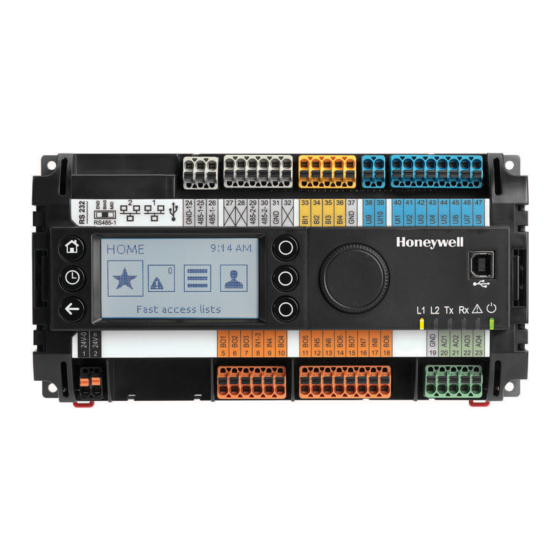
MODEL 50 CONTROLLER
USER GUIDE
July 2021
31-00198-03

Advertisement

Table of Contents
loading

Summary of Contents for Honeywell CIPer 50

  • Page 1 MODEL 50 CONTROLLER USER GUIDE July 2021 IMPORTANT NOTE: Email your Host Id to Honeywell WEBs Customer Care (websliense@honeywell.com), so that we can move the license to your organization. For additional queries contact your distributor. ® U.S. Registered Trademark 31-00198-03...
  • Page 2 Honeywell makes no representations or warranties with respect to this document. In no event shall Honeywell be liable for technical or editorial omissions or mistakes in this document, nor shall it be liable for any damages, direct or incidental, arising out of or related to the use of this document. No part of this document may be reproduced in any form or by any means without prior written permission from Honeywell.
  • Page 3: Table Of Contents

    CIPer MODEL 50 CONTROLLER – USER GUIDE TABLE OF CONTENTS Order numbers (SKU)................................5 HMI configuration principles ..................................6 HMI Service ..........................................7 HMI pin ...........................................9 HMI user rights ........................................9 HMI PIN lock-out.......................................10 Enabling the alarming on the HMI ................................11 Enabling the alarm LED on the HMI ................................11 Adjusting alarm poll-rate for the HMI ..............................12 Local language HMI menus - translation .............................13 Login user into the HMI and control the translation ........................13...
  • Page 4 CIPer MODEL 50 CONTROLLER – USER GUIDE CIPer Model 50 Firmware....................................34 Firmware & Hardware compatibility ..............................34 Firmware upgrade......................................34 Restore the CIPer Model 50 controller ..............................35 Resetting CIPer Model 50 controller ...............................37 Cable ...........................................37 Technical Documentation ....................................39 Appendix ..................................... 40 USB Driver Installation for Windows 7 ..............................40 USB Driver Installation for Windows 8 ..............................43 USB Driver Installation for Windows 10 ..............................46 31-00198-03...
  • Page 5: Order Numbers (Sku)

    • WEB-EHSERIESNX26ND IMPORTANT To make efficient use of HMI functionality, it is required to do a few set-up steps in Honeywell WEBStation N4.4.93 or higher. Refer to section HMI configuration principles given below. WEB-EHSERIESNX26D The XL2000HMI can be connected and operated with the below listed OS (SKU) numbers.
  • Page 6: Hmi Configuration Principles

    CIPer MODEL 50 CONTROLLER – USER GUIDE HMI configuration principles To get the onboard HMI or detached HMI operational, the following configuration principles need to be done in WEBs N4: Add & enable the HMI Service. Set a PIN for the HMI access. Add HMI and LED Alarm recipients.
  • Page 7: Hmi Service

    CIPer MODEL 50 CONTROLLER – USER GUIDE HMI Service The onboard and detached HMI will only work when the HMI Service, called “HonEagleHawkHmiService” has been placed into the “Services” of your station. IMPORTANT Always place the “HonEagleHawkHmiService” into the “Services” folder. Do NOT place it under any service within “Services”...
  • Page 8 CIPer MODEL 50 CONTROLLER – USER GUIDE For translating the “Warning” and “Welcome” message of the HMI, you can also use the WEBs N4 Lexicon tool, see section “Local language HMI menus – translation” in this bulletin 31-00198-03...
  • Page 9: Hmi Pin

    CIPer MODEL 50 CONTROLLER – USER GUIDE HMI pin PIN, PIN-configuration, and log-off definition are fully integrated with the Niagara “User Service”. This makes it secure and allows to re-use the user definitions already in place for the station. NOTE It is mandatory to enter a 5-digit (Numeric only) PIN here.
  • Page 10: Hmi Pin Lock-Out

    CIPer MODEL 50 CONTROLLER – USER GUIDE HMI PIN lock-out For Cyber Security reasons, users will be locked out after multiple entries of a wrong PIN: • After three wrong PIN entries in a row, user login is blocked for 1 min. For each wrong PIN after this, the user must wait for 1 min.
  • Page 11: Enabling The Alarming On The Hmi

    CIPer MODEL 50 CONTROLLER – USER GUIDE Enabling the alarming on the HMI From the “honEagleHawkHMI” palette, drag the “HmiAlarmConsoleRecipient” into the “Alarm Service” and connect it to the “Default Alarm Class". Enabling the alarm LED on the HMI From the “clOnboardIO” palette, drag the “EagleHawkLedRecipient” into the “Alarm Service” and connect it to the “Default Alarm Class”: 31-00198-03...
  • Page 12: Adjusting Alarm Poll-Rate For The Hmi

    CIPer MODEL 50 CONTROLLER – USER GUIDE Adjusting alarm poll-rate for the HMI The update rate for alarms and data points on the HMI has a default setting. This can be adjusted with the CPU performance, to balance the information demand. IMPORTANT i).
  • Page 13: Local Language Hmi Menus - Translation

    CIPer MODEL 50 CONTROLLER – USER GUIDE Local language HMI menus - translation The HMI menus can be localized by making use of the standard Lexicon tool of WEBs N4: • Open Lexicon tool of WEBs N4 and your local language lexicon file •...
  • Page 14: Filling The Fast Access Lists

    CIPer MODEL 50 CONTROLLER – USER GUIDE Filling the Fast Access Lists To fill the Fast Access Lists (FAL) with points, parameters, and schedules, you have two options: • Option 1: Drag and drop points from the Navigation tree on the left into the Fast Access List on the property sheet on the right.
  • Page 15: Setting The Time Format On The Home Screen

    CIPer MODEL 50 CONTROLLER – USER GUIDE Setting the time format on the home screen Make sure that the Lexicon of the desired local language is installed. If not, use the Lexicon Installer to install it. Set the language in the Station/PlatformService “locale” field. 31-00198-03...
  • Page 16: Onboard Inputs And Outputs

    CIPer MODEL 50 CONTROLLER – USER GUIDE Onboard Inputs and Outputs Onboard Max. cable WEB- Description WEB-EHSERIESNX26D Inputs/Outputs length EHSERIESNX26ND NTC10kΩ (Type II), NTC20kΩ (Type II), 1200 ft 0…10V, slow BI 0.4 Hz (366 m) Short-circuit protected against 24VAC UI (Universal Input) NTC10kΩ...
  • Page 17: Dual Ethernet

    CIPer MODEL 50 CONTROLLER – USER GUIDE Dual Ethernet The CIPer Model 50 is equipped with a Dual Ethernet interface. All information about the Dual Ethernet can be found in the CIPer Model 50 Installation & Commissioning Instructions – 31-00233. Separated networks SEPARATED NETWORKS = DEFAULT SETTING For cybersecurity reasons, the default setting of the Dual Ethernet is with the following IP settings:...
  • Page 18: Network Switching Mode

    CIPer MODEL 50 CONTROLLER – USER GUIDE Network switching mode Optionally, the Dual Ethernet can be operated in network switching mode. If this mode is desired, disable one of the Ethernet ports in WEBs N4 – see screenshot below. Typical application scenarios are a closed BMS networks, like for daisy-chaining plant controllers or daisy-chaining room controllers on Ethernet.
  • Page 19: Combined Network Switching & Separated Networks

    CIPer MODEL 50 CONTROLLER – USER GUIDE Combined network switching & separated networks Optionally separating networks and switching functionality can be combined. This allows to have one (or more) controllers connected to the customer intranet, and all other controllers residing in a closed BMS network.
  • Page 20 CIPer MODEL 50 CONTROLLER – USER GUIDE ATTENTION: Due to the risk of short-circuiting (see below figure), it is strongly recommended that the CIPer Model 50 controller be supplied with power from a dedicated transformer. However, if the CIPer Model 50 controller is to be supplied by the same transformer powering other controllers or devices (e.g., the PW M-Bus Adapter), care must be taken to ensure that correct polarity is observed.
  • Page 21: Secure Boot - Increased Cyber Security

    Beginning with the firmware of this release, the CIPer Model 50 will only boot and run authenticated WEBs N4 firmware. This is achieved by a firmware signature. To achieve the best possible cybersecurity, please note the following: Read and apply the Honeywell General Security Best Practices - 31-00129, available at the Honeywell Buildings Forum.
  • Page 22: Part Numbers And Supporting Material

    CIPer MODEL 50 CONTROLLER – USER GUIDE Part numbers and supporting material Ordering Part Numbers Table 1. Ordering Part Numbers OS Number (SKU) Description WEB-EHSERIESNX26D CIPer Model 50 PLANT CONTROLLER, w/ HMI, 26 IO, 100 points, 5 devices WEB-EHSERIESNX26ND CIPer Model 50 PLANT CONTROLLER, w/o HMI, 26 IO, 100 points, 5 devices CIPer MODEL 50 CORE LICENSE with SMA-0005-1YR-INT WEBSEHN4LIC PIN-0005 - 18 mo Maintenance...
  • Page 23: Performance

    “traffic” created by the application, concurrent polls from Supervisors, Station Save intervals, Recovery Service intervals, etc. In addition to the general Tridium guidance of a maximum of 80% CPU load, Honeywell has undertaken two exemplary performance tests.
  • Page 24: Panelbus Communication Tuning

    CIPer MODEL 50 CONTROLLER – USER GUIDE PanelBus Communication tuning The default polling time for all Panel-Bus points is set to “Normal = 10s”. This means that the data from the field are updated every 10s. Write commands are sent without time delay. The polling frequency can be changed, and we do recommend that it must be updated more frequently.
  • Page 25: Panel-Bus Cable Type And Length

    2400 ft (731.5m) for twisted-pair or telephone cable and daisy chain topology. The Controller must be positioned at one end of the Panel-Bus, and an end termination (120 Ω) at the other end. Furthermore, the three-position slide switch must be set to "END." Use Honeywell cable 3322 or 3251. 31-00198-03...
  • Page 26: I/O Modules

    CIPer MODEL 50 CONTROLLER – USER GUIDE I/O Modules Pluggable I/O Modules There are 2 variants of pluggable I/O modules: • Panel Bus I/O modules with communication via Panel Bus (light-gray housings). Panel Bus I/O modules are automatically commissioned (with firmware download) by the CIPer Model 50 Controller. •...
  • Page 27 CIPer MODEL 50 CONTROLLER – USER GUIDE Pluggable Pluggable Pluggable Pluggable Relay Pluggable Mixed I/O Analog Input Analog Output Binary Input Output Floating Output LonWorks MODULE PANEL MODULE XFU830A XFR825A CIPer Model LonWorks or Panel Bus 31-00198-03...
  • Page 28: Lonworks Product Material Number Substitution Information

    XFLR824A 6 RELAY OUTPUT MODULE (LON) W/OVR NOTE: If you do not purchase products directly from Honeywell, please coordinate purchases of the ‘End of Life’ products with your current supplier. In this case, recognize that your supplier must meet the outlined ‘Last Time Buy’...
  • Page 29: Compatibility

    WEBs 4.4U2 or higher is mandatory for CIPer Model 50, also the related jar files and modules to run the CIPer Model 50 with HMI. Downloaded the workbench version WEBs N4.4.93 or higher from the Honeywell Buildings Forum. For compatibility of WEBs N4, please refer to the latest Release Bulletin.
  • Page 30: Spyder & Stryker Tool Compatibility

    They are supported as 3 party LON and BACnet devices. The CIPer Model 50 comes with a Honeywell license with the features required to program a non-ILC Spyder. party modules Support and distribution of WEBs N4 modules that have been developed and distributed by 3...
  • Page 31 Honeywell Panelbus Platform Service 4.10.0.2.0.12 Steps to install into WEBs N4 Shut-down CIPer Model 50 controller. Copy the *.jar files into the folder “c:\Honeywell\WEBStation-N4-4.x.x.xx\modules\” on your PC where the WEBStation N4 installation resides. Restart WEBStation N4 workbench. NOTE While booting the controller station, a warning displays in the application directory.
  • Page 32: Webs N4 Driver Compatibility

    CIPer MODEL 50 CONTROLLER – USER GUIDE WEBs N4 Driver compatibility Supported Drivers Protocol Default Port Hardware Interface(s) Platform Daemon 3011 Ethernet RJ45, IP via USB-B Platform Daemon SSL 5011 Ethernet RJ45, IP via USB-B Station (FOX) 1911 Ethernet RJ45, IP via USB-B Station Secure (FOXS) 4911 Ethernet RJ45, IP via USB-B...
  • Page 33: Web-Browser Compatibility

    CIPer MODEL 50 CONTROLLER – USER GUIDE Information on HTTP and HTTPS ports: WEBs-N4 Version N4.4.93 or higher includes a template which automatically changes these two ports to 8080 (HTTP) and 8443 (HTTPS), when creating a new station. Un-supported Drivers Protocol Hardware Interface(s) CCTV...
  • Page 34: Ciper Model 50 Firmware

    Open WEBs N4, go to the Platform/Platform Administration, and check the version of the Niagara Runtime for the CIPer Model 50 installed. Firmware updates may be available on the Honeywell Buildings Forum and the firmware upgrade procedure will be available with the firmware updates. If there are any queries on Firmware updates, please reach out to your WEBs technical support.
  • Page 35: Restore The Ciper Model 50 Controller

    If the upgrade still not successful after signing the third-party modules, then you should perform the factory reset using the clean-dist-honeywell-nxubc.dist file. Choose one of the following "CleanDist" files to delete and restore settings on the CIPer Model 50 controller.
  • Page 36 The base firmware does not allow to start a station and therefore it must be upgraded to the appropriate firmware version using the Commissioning Wizard. Before performing CIPer 50 controller rstoring process, make sure to copy clean dist file in the C:\Honeywell\WEBStation-N4-4.x.x.xxx\cleanDist folder.
  • Page 37: Resetting Ciper Model 50 Controller

    CIPer MODEL 50 CONTROLLER – USER GUIDE Resetting CIPer Model 50 controller To reset the CIPer Model 50 controller, the user needs to delete the following • Passphrase • Username • Password • Ethernet IP • Station NOTE In order to delete Modules, the “Clean dist file” needs to be downloaded. Cable Using the following two cables connected end-to-end, TECHTOO USB 3.0 and YIOVVOM DB9 Breakout Connector, setup a connection between the CIPer Model 50 and a terminal program (Putty) via RS232.
  • Page 38 CIPer MODEL 50 CONTROLLER – USER GUIDE NOTE TECHTOO USB 3.0 to Serial Adapter USB RS232 Cable USB Serial Cable Converter DB9 USB (10ft) with FTDI Chipset Gold Plated for Win10/8.1/8/7/Vista/XP/2000/Android/Linux/Mac OS X10.6 & Above. YIOVVOM DB9 Breakout Connector to Wiring Terminal RS232 D- SUB Male Serial Adapters Port Breakout Board Solder-Free Module with case (Female Serial Adapter).
  • Page 39: Technical Documentation

    The default primary interface IP address is 192.168.200.20 and the subnet mask is 255.255.255.0 Technical Documentation Product Document type Document name WEBs Honeywell General Security Best Practices 31-00129 CIPer Model 50 Product Data Sheet 31-00197 CIPer Model 50 Mounting Instructions...
  • Page 40: Appendix

    CIPer MODEL 50 CONTROLLER – USER GUIDE Appendix USB Driver Installation for Windows 7 Insert the A Male connector of the USB cable into an USB interface jack of the PC and insert the B Male connector into the controller´s USB device interface jack. RESULT: The Found New Hardware Wizard is enabled in the Windows Task Line.
  • Page 41 CIPer MODEL 50 CONTROLLER – USER GUIDE In Control Panel \ Network and Internet \ Network Connections. In Control Panel \ Device Manager \ Network Adapters If the driver has still not been successfully installed, do the following: Right-click on the driver in the Network adapters folder in the Device Manager, and then click Update Driver Software.
  • Page 42 CIPer MODEL 50 CONTROLLER – USER GUIDE Click OK. Select Linux USB Ethernet/RNDIS Gadget, and then click Next>. If a warning message displays, click Continue Anyway. RESULT: Windows will install the driver. Click Close. Check the successful installation of the driver as described in step 5. If this still does not work, use the driver shipped with Windows.
  • Page 43: Usb Driver Installation For Windows 8

    CIPer MODEL 50 CONTROLLER – USER GUIDE USB Driver Installation for Windows 8 Insert the A Male connector of the USB cable into a USB interface jack of the PC and insert the B Male connector into the controller´s USB device interface jack. In Windows, start the device manager.
  • Page 44 CIPer MODEL 50 CONTROLLER – USER GUIDE Click Let me pick from a list of device drivers on my computer. Select Network adapters. 31-00198-03...
  • Page 45 CIPer MODEL 50 CONTROLLER – USER GUIDE Select Microsoft. Select USB-RNDIS-Adapter, and then click Next button. RESULT: The Update Driver Warning message box displays. 31-00198-03...
  • Page 46: Usb Driver Installation For Windows 10

    If you have issues with the installation, please contact the manufacturer of your PC to obtain updates on the chipset driver. Honeywell Building Technologies 1985 Douglas Drive North ® U.S. Registered Trademark Golden Valley, MN 55422 © 2020 Honeywell International Inc. 31-00198-03 | Rev 07-2021 customer.honeywell.com Honeywell Building Controls...

This manual is also suitable for:

Web-ehseriesnx26dWeb-ehseriesnx26nd

Table of Contents