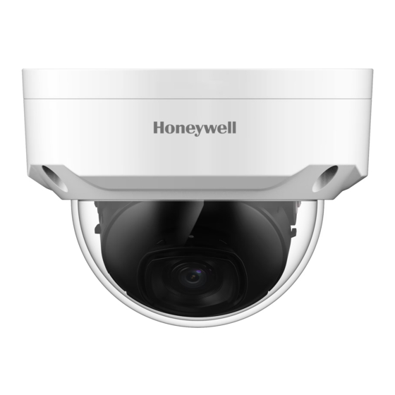
Summary of Contents for Honeywell Performance Series
Page 1
H4W8PER1V HBW8PER1V HEW8PER1V User Guide Recommended Find the latest version of this and other Performance Series IP camera documents on the Honeywell Video website. Go to: https://www.security.honeywell.com/All-Categories/video- systems/performance-series-ip-cameras to find your camera and view/download the latest documentation. Refer to the Honeywell Open Technology Alliance to learn more about our open and integrated solutions (go to: http://www.security.honeywell.com/hota/).
Page 2
Revisions Issue Date Revisions 03/2021 New document.
Page 3
Cautions and Warnings WARNING Installation and servicing should be performed only by qualified and experienced technicians to conform to all local codes and to maintain your warranty. WARNING To ensure compliance with electrical safety standards this product is intended for use with a Listed Power Adapter marked with “Limited Power Source”, “LPS”, on the unit, output rated 12 V DC, minimum 0.7A, Tma=60°C or from Power over Ethernet (PoE) provided by Listed Information Technology Equipment meeting the IEEE 802.3af PoE standard.
Page 4
• Connect the equipment into an outlet on a circuit different from that to which the receiver is connected. • Consult the dealer or an experienced radio/TV technician for help. Changes or modifications not expressly approved by the party Note responsible for compliance could void the user’s authority to operate the equipment.
Page 5
Product Part Name Substance Name Number HBW8PER1V Crystal (X1), TVS tube (TVS1,TVS2, D14), Fixed Lead 7439-92-1 Focus Lens (M12/M16 etc.), FFC, Cable, IPC Cable HBW4PER1V Crystal (X1,X2), Rectifier diode (D13), TVS tube (D9), Lead 7439-92-1 Fixed Focus Lens (M12/M16 etc.), FFC, Cable, IPC Cable HEW8PER2V Crystal (X1), TVS tube (TVS1,TVS2,D14), Rectifier...
Page 6
H4W8PER2V Crystal (X1), TVS tube (TVS1,TVS2,D21,D14), IPC Lead 7439-92-1 Cable H4W4PER2V Crystal (X2), Rectifier diode (D5), TVS tube (D9), Lead 7439-92-1 FFC, IPC Cable H4W2PER2V Crystal (X1), Rectifier diode (D12), TVS tube Lead 7439-92-1 (TVS1,TVS2,D7), IPC Cable General Data Protection Regulation Please be aware that this product can store personal data.
Page 7
Honeywell will repair or replace, at its sole option, free of charge, any defective products returned prepaid. In the event you have a problem with any Honeywell product, please call Customer Service at 1.800.323.4576 for assistance or to request a Return Merchandise Authorization (RMA) number.
Table of Contents Introduction ..................................1 Overview ............................1 Key Features ............................ 1 Accessing the Camera ..............................3 Installing the Unified Tool ......................... 3 Discovering Your Camera on the Network ..................5 Assigning a New IP Address to Your Camera .................. 6 Upgrading the Camera’s Firmware ....................
Page 15
About This Document This document provides instructions for accessing, configuring, and operating the Performance Series IP cameras. This document is intended for system installers, administrators, and operators. Overview of Contents This document contains the following chapters and appendixes: • Chapter 1, Introduction, provides an overview of the main features of the Performance Series IP cameras.
You can monitor Performance Series IP cameras from anywhere, at any time, using the free HonView Touch mobile app for both Apple and Android smartphones and tablets. Key Features Key features of the Performance Series IP cameras include the following (* - the feature is only supported by certain models.): Camera •...
Page 17
Performance Series IP Camera Software Configuration Guide • Backlight compensation • Video watermark function to prevent modification • IR night vision Storage • Central server backup (configure in Alarm or Schedule settings) • Recording over Internet, files stored on client PC •...
To get the installation package of Unified Tool: • Browse to https://mywebtech.honeywell.com, login, navigate to Download Center Video IP Cameras Camera Discovery Tools & Utilities Honeywell Unified Tool. Download and unzip the installation package of Unified Tool to your computer. •...
Performance Series IP Camera Software Configuration Guide 2. Click Next and the following figure is displayed: Figure 2-2 Select Installation Folder 3. Follow the on-screen instructions to configure your settings and click Next. The following figure is displayed: Figure 2-3 Confirm Installation 4.
Accessing the Camera Discovering Your Camera on the Network Double-click on the desktop and the following figure is displayed: Figure 2-4 Splash Screen 1. Select your language from the dropdown list of Language. Currently, only English is supported. 2. Check “Don’t show the splash window on startup” and this page can be skipped next time. If you want to check the splash window again, click as shown in Figure 2-6...
Performance Series IP Camera Software Configuration Guide Figure 2-5 Scanning the network After the scanning, all scanned devices in the same subnet and different subnet will be displayed in the devices list. Figure 2-6 Device List Assigning a New IP Address to Your Camera The current IP address of your camera appears in the IP ADDRESS column of the devices list.
Accessing the Camera Select the target device(s) as shown in Figure 2-6, click and the following figure is displayed: Figure 2-7 IP Assignment Configure IP Address Setting • To obtain IP address, subnet mask, and default gateway settings automatically, select the check box of DHCP.
Performance Series IP Camera Software Configuration Guide Select the Maintenance tab from the left pane as shown in Figure 2-6, select target device(s) and click and the following window is displayed: Figure 2-8 Firmware Upgrade The devices were grouped by model. To upgrade the firmware: 1.
Logging In and Viewing Live Video 3 Logging In and Viewing Live Video This chapter contains the following sections: • Logging In to the Camera via the Web Client, page 9 • Using the Live View , page 12 Logging In to the Camera via the Web Client Using the web client, you can monitor live video, play back recorded video, and configure camera settings.
Performance Series IP Camera Software Configuration Guide Figure 3-1 Login Interface For security purposes, you are required to create a new secure password at the first login. The password must be at least 8 characters long and contain at least one lowercase letter, one number, and one special character.
Logging In and Viewing Live Video Figure 3-2 Security Certificate Problem 2. A message appears asking if you want to run or save the file. Figure 3-3 File Download Security Warning Message for the Plug-in 3. Click Run to start the installation. 4.
Performance Series IP Camera Software Configuration Guide Using the Live View Interface The Live View window has four areas with controls and options for monitoring live video. Figure 3-4 Live View Interface 1. Video encoder settings area (see Video Encoder Settings, page 2.
Logging In and Viewing Live Video You can select the stream media protocol from the drop- down list. There are three options: TCP, UDP, or Multicast. TCP: Provides most reliable data transmission. Higher latency and bandwidth use than UDP. UDP: Provides fastest data transmission. Lower latency and Protocol bandwidth use than TCP but allows some data loss (such as dropped frames).
Performance Series IP Camera Software Configuration Guide Icon Control Description Click to enable Easy Focus. You can see AF Peak and AF Max adjustments on the Preview window. Select from AF Peak and AF Max. Easy Focus AF Peak: Displays the video’s definition when focusing.
Logging In and Viewing Live Video Table 3-3 Live View Window Configuration Tools Click to open the Image Adjustment panel. Move the sliders to adjust the image brightness, contrast, hue, or saturation. Click the – and + signs to make fine adjustments. To restore the settings to their Image Control default values (64), click Reset.
Performance Series IP Camera Software Configuration Guide 4 Playing Back Video This chapter contains the following sections: • Introduction, page 16 • Playing Back Recorded Video, page 17 • Using the Playback Assistant, page 20 • Creating a Video Clip, page 20 •...
Playing Back Video Overview of the Playback Interface The Playback interface has six areas with controls and options for playback (see Figure 4-1). Figure 4-1 Playback Interface Playback controls (see Playback Controls on page Calendar area (see Playing a Recorded File from the Calendar on page Clip selection (see Creating a Video Clip on page Recording type (see...
Performance Series IP Camera Software Configuration Guide Control Description Slow playback Fast playback Mute sound Volume control Rules Info Playing a Recorded File from the Calendar On the playback calendar, a day in red indicates a day on which video was recorded and a day in blue indicates the day you select.
Playing Back Video • Yellow – Motion detection recording • Red – Alarm-triggered recording. • Blue – Manual recording. Figure 4-4 Recording Timeline Below the calendar, click the File List button to narrow your search by time period and/or by download format. Play the file using one of the following methods: •...
Performance Series IP Camera Software Configuration Guide recording type to display in the Playback interface. The filter is at the bottom of the Playback interface. Figure 4-6 Record Type Filter in Playback Timeline Configuration You can configure the playback timeline in Playback to show the last 24 hours, 2 hours, 1 hour, or 30 minutes of recorded video.
Playing Back Video Note This function is not supported by model HBW2PER1V. Figure 4-8 Clip Function Controls Find the recording that you want to create a clip from. On the timeline, click the recording at the time you want to start the clip, and then click .
Performance Series IP Camera Software Configuration Guide 5 Configuring Camera Settings This chapter contains the following sections: • Configuring Camera Conditions, page 22 • Configuring Video Settings, page 29 • Configuring Audio Settings, page 33 Configuring Camera Conditions Go to Setup Camera Setup Conditions.
Page 38
Configuring Camera Settings Profile From the Profile list, select the camera profile that you want to configure settings for: Normal, Day, or Night. Picture In the Picture field, select a picture style from the Style list: Soft, Standard, or Vivid. To adjust the image brightness, contrast, saturation, sharpness, or gamma settings, drag the slider left or right or click the –...
Page 39
Performance Series IP Camera Software Configuration Guide Gamma Adjusts dynamic range. Choosing a higher value increases the brightness of the image non- linearly. Select from 0 to 100. The recommended range is between 40 and 60. The default value is 50.
Page 40
Configuring Camera Settings Backlight In the Mode field, you can apply backlight compensation (BLC), highlight compensation (HLC), or wide dynamic range (WDR) adjustment to the image. Set Lighting Mode to OFF, BLC, HLC, or WDR. By lowering the brightness of the brightest area, and enhancing the brightness of the darkest area, WDR balances brightness and darkness in a scene so that both the darkest area and the lightest area can be seen clearly at the same time.
Performance Series IP Camera Software Configuration Guide By default, the camera automatically outputs color video or black-and-white video depending on the amount of light in the scene. To output only color video, set Mode to Color. To output only black-and-white video, set Mode to Black & White.
Configuring Camera Settings Figure 5-2 Profile Management The Profile Management has three modes: Normal, Full Time, and Schedule. By default, the system has the Day profile always enabled. • Normal: The Normal profile is always enabled. • Full Time: The Day profile or Night profile is always enabled, depending on your selection. •...
Performance Series IP Camera Software Configuration Guide Zoom and Focus Go to Setup Camera Setup Conditions Zoom and Focus. This section only applies to HEW4PER2V/HEW2PER2V/H4W2PER2 Note V/HBW2PER2V motorized focus/zoom cameras. Figure 5-4 Zoom and Focus Table 5-1 Zoom and Focus...
Configuring Camera Settings Configuring Video Settings Go to Setup Camera Setup Video. This section describes how to configure video streaming properties (format, resolution, frame rate, bit rate, I-frame interval, etc.). Video Stream Go to Setup Camera Setup Video Video. Figure 5-5 Video Stream Encode Mode In the Encode Mode box, select H.264B, H.264, H.264H, MJPEG, or H.265.
Page 45
Performance Series IP Camera Software Configuration Guide By taking reference frames and applying them to refreshed frames, Smart Codec eliminates the need to transmit data for an unchanged image or parts of the image where there is no movement. Used together with H.264, Smart Codec can lead to storage savings of up to 60 percent and bandwidth savings of up to 40 percent over H.264 alone.
Configuring Camera Settings Snapshot Go to Setup Camera Setup Video Snapshot. Figure 5-6 Snapshot Table 5-2 Snapshot Configurations Parameter Function Select from either General (schedule) or Event (activation). General: Snapshots are taken according to a user-defined Snapshot Type schedule.
Performance Series IP Camera Software Configuration Guide Figure 5-7 Video Overlay Table 5-3 Video Overlay Configurations Parameter Function Masks areas of the video for privacy. To enable privacy masking, click Enable. Four privacy masks appear in the preview window. Delete any masks that you don’t need. To delete a mask, right-click it or Privacy select it and then click Delete.
Configuring Camera Settings To delete a single region of interest, select it, and then click Delete. To delete all regions of interest, click Remove All. Path Go to Setup Camera Setup Video Path. Figure 5-8 Storage Path Set the storage path for snapshots ( in the live interface) and for recorded video ( the live interface).
Performance Series IP Camera Software Configuration Guide Figure 5-9 Audio To enable audio for the stream, select the Enable check box, select the format (G.711A, G.711Mu, G.726, AAC), and then select a sampling frequency (8–64 kHz). In the Conditions area, select the audio input type (LineIn or Mic), enable or disable noise filtering, and adjust the microphone and/or speaker volumes by moving the sliders.
Performance Series IP Camera Software Configuration Guide Table 6-1 TCP/IP Configurations Parameter Function Configure to set the current host camera’s name. Hostname Maximum 32 characters. Select an Ethernet port. The default is Wire (Default). Ethernet Card Note If you modify these settings, you should reboot your camera to activate the new setup.
Configuring Network Settings Parameter Function 5. Close the command line. Open your browser, type http://<IP address> in the address bar, and then press Enter. Configuring Port Settings Go to Setup Network Setup Port. Figure 6-2 Port Port Table 6-2 Port Configurations Parameter Function Displays the maximum number of network connections for the same...
Performance Series IP Camera Software Configuration Guide Parameter Function HTTPS The default setting is 443. Port ONVIF Figure 6-3 ONVIF ONVIF (Open Network Video Interface Forum) is a global open standard for the interface of IP-based security products. It covers network video mode, interface, data type, and data interaction mode.
Configuring Network Settings Figure 6-5 PPPoE To enable PPPoE, select the Enable checkbox. Enter the PPPoE user name and password that you received from your Internet service provider (ISP). Click Save to save the current setup, and then reboot the camera to activate this new setup.
Performance Series IP Camera Software Configuration Guide Parameter Function Supports the anonymity function for the server. You can Anonymous automatically log in anonymously. You do not need to enter the user name, password, and the sender information. User Name Enter the username for the sender’s email Password Enter the password for the sender’s email...
Configuring Network Settings Figure 6-7 UPnP Enabling UPnP in Windows The UPnP protocol is used to detect network devices with clients running Windows. To enable UPnP, select the Enable check box. The camera can now be detected by Windows' built-in network browser (My Network Places in Windows XP; Network in Windows 7). To enable UPnP in Windows XP: 1.
Performance Series IP Camera Software Configuration Guide Figure 6-8 SNMP Table 6-4 SNMP Configurations Parameter Function SNMP Version When SNMP v1 is selected, the device can only process SNMP v1 information. When SNMP v2 is selected, the device can only process SNMP v2 information.
Configuring Network Settings Configuring Bonjour Settings Go to Setup Network Setup Bonjour. Bonjour is based on the multicast DNS service from Apple. It can automatically broadcast its service information and listen to the camera information from the other camera. Figure 6-9 Bonjour Bonjour is a zero configuration networking application that allows you to create a network in which devices can discover each other without requiring any user configuration.
Performance Series IP Camera Software Configuration Guide Table 6-5 Multicast Configurations Parameter Function Select the check box to enable the multicast function. Enable Note Main stream and sub stream cannot be used at the same time. Multicast The main/sub stream multicast address is 224.1.2.4 and its range is Address 224.0.0.0 ‒...
Configuring Network Settings Configuring Firewall Settings Configure Network Access, PING prohibited and Prevent Semijoin to enhance network and data security. This section takes Network Access as an example. Network Access: Set trusted list and restricted list to limit access. • •...
Performance Series IP Camera Software Configuration Guide Figure 6-13 Add IP/MAC Table 6-7 Add IP/MAC Configurations Parameter Function Select IP address, IP segment, MAC address or all IP addresses. • IP address: Select IP version and enter the IP address of the host to be added.
When you log in to the camera’s web client for the first time, some browsers may display a warning that the connection is not private/secure. To access the web client, you must install a Honeywell-signed security certificate. Figure 6-15 Certificate Certificate To install a Honeywell-signed root certificate:...
Page 63
Performance Series IP Camera Software Configuration Guide 1. Click Export, navigate to the directory where you want to save the certificate (ca.crt) on your PC, and then click Save. 2. Go to the directory where you saved the certificate and double-click the certificate. The Certificate window opens.
Configuring Video Analytics Settings Figure 7-1 Motion Detection Table 7-1 Motion Detection Configurations Parameter Function Enable Check to enable Motion Detection. The camera Motion Detection function is activated during the specified period. Configuring the Alarm Period on page 51. Period You can configure up to six periods per day.
Performance Series IP Camera Software Configuration Guide interacts with the linked alarm devices. The Alarm linkage keeps running for the configured time after alarm is Alarm Delay ended. Send Email When enabled, the system sends an email alert when an alarm occurs.
Configuring Video Analytics Settings Method 1: 1. Select a day of the week check box. Select from a day of the week or All. • If you select All, the schedule will apply to all days of the week. Note •...
Performance Series IP Camera Software Configuration Guide 3. Select a sensitivity value, from 1 to 100 for each region. The higher the number, the higher the motion detection sensitivity. It is recommended that you choose a sensitivity between 30 to 70. The default is 60.
Configuring Video Analytics Settings HEW4PER2V/HEW2PER2V/H4W2PER2V/HBW2PER2V. The video tampering function is activated during the specified period. Configuring the Alarm Period on page 51. You can configure up to six periods per day. Select a date. If you do Period not select a date, the current setup will be applied to today only. You can select All to apply the alarm period to the whole week.
Performance Series IP Camera Software Configuration Guide Table 7-3 Scene Change Configurations Parameter Function Enable Check to enable scene change. The camera scene change function is activated during the specified period. Configuring the Alarm Period on page 51. Period You can configure up to six periods per day. Select a date. If you do not select a date, the current setup will be applied to today only.
Configuring Video Analytics Settings Figure 7-6 Audio Detection Table 7-4 Scene Change Configurations Parameter Function Enable Input Select Enable Input Abnormal and it will trigger alarms when it detects Abnormality audio input abnormity. Enable Intensity Select Enable Intensity Change and it will trigger alarms when it detects Change that audio intensity change exceeds the threshold.
Performance Series IP Camera Software Configuration Guide Click OK to save the changes. The system goes back to the scene change interface. Click Save to exit. Enter the anti-dither time in seconds. Enter a value between 0 and 100 Anti-Dither seconds.
Configuring Video Analytics Settings Figure 7-8 Configuring IVS Tripwire: When the target crosses tripwire from the defined motion direction, the • system performs alarm linkages. Intrusion: When the target enters, leaves, or appears in the detection area, the system • performs alarm linkages.
Performance Series IP Camera Software Configuration Guide Click Draw Target at the right side of Pixel Counter, and then press and hold the left mouse button to draw a rectangle, the Pixel Counter then displays its pixel. Set rule parameters for IVS.
Configuring Video Analytics Settings Figure 7-9 Face Detection To enable face detection: 1. Select the Enable check box. 2. (Optional) Click Draw next to Detect Region to draw a face detection area in the image. 3. (Optional) Click Draw next to Exclude Region to draw a non-face detection area in the Detect Region.
Performance Series IP Camera Software Configuration Guide time after the camera detects face. Quality Priority: Repeatedly compare the captured face to the faces in the armed face database and capture the most similar face image and send the alarm. It is recommended to use this mode in access control scene.
Configuring Video Analytics Settings Figure 7-10 No SD Card Warning Figure 7-11 SD Card Error Warning Configuration Interface Figure 7-12 Capacity Warning Table 7-7 SD Card Configurations Parameter Function Event Select an event type in the dropdown list. Type Enable Check to enable the selected event type Relay-out Select the Relay-out check box, and when alarm is triggered, the system...
Performance Series IP Camera Software Configuration Guide interacts with the linked alarm devices. Alarm The Alarm linkage keeps running for the configured time after alarm is Delay ended. Send When enabled, the system sends an email alert when the event occurs.
Configuring Video Analytics Settings Configuring Illegal Access Event Settings Abnormality Go to Setup Video Analytics Illegal Access. You can specify how many unsuccessful login attempts can be made before the system triggers an illegal access alarm. Figure 7-14 Illegal Access Configuration Table 7-9 Illegal Access Configurations Parameter Function...
Performance Series IP Camera Software Configuration Guide Voltage Detection Figure 7-15 Table 7-10 Voltage Detection Configurations Parameter Function Enable Check to enable the Voltage Detection function. Check it, and the alarm icon is displayed by overlapping when the alarm is Overlay triggered.
Configuring Storage Settings 8 Configuring Storage Settings This chapter contains the following sections: • Configuring Schedule Settings, page 67 • Configuring Destination Settings, page 68 • Configuring Record Control, page 71 Configuring Schedule Settings Configuring Record Schedule Go to Setup Storage Schedule Record Schedule. You can add or remove schedules for recording.
Performance Series IP Camera Software Configuration Guide Setting Holidays Go to Setup Storage Setup Schedule Holiday Schedule. You can designate holidays by clicking dates on the calendar. On the selected dates, the video recording/snapshot schedule will follow the holiday settings you configured in the Record Schedule and Snapshot Schedule tabs.
Configuring Storage Settings Table 8-1 Path Configurations Parameter Function Event Type Select Scheduled, Motion Detection, or Alarm. Local Select to save files to the microSD card SFTP Select to save files to the SFTP server. Select to save files to the NAS disk. Local If the camera has a microSD card installed, the Local tab displays the microSD card details.
Performance Series IP Camera Software Configuration Guide Figure 8-5 SFTP Table 8-2 SFTP Configurations Parameter Function Enable Check to enable the SFTP storage function. Server Address Enter the IP address of the SFTP server. The default setting is 21. You can modify this setting as Port necessary.
Configuring Storage Settings Set storage directory where recorded video and snapshots will be Remote Directory stored. Configuring Record Control Go to Setup Storage Setup Record Control. Figure 8-7 Record Control Table 8-4 Record Control Configurations Parameter Function Pack Duration Set the file size between1 to 120 minutes. The default is 8 minutes. Enter a pre-record value.
Performance Series IP Camera Software Configuration Guide 9 Configuring System Settings This chapter contains the following sections: • General System Setup, page 72 • Account Setup, page 73 • Restoring Default Settings, page 78 • Import/Export, page 79 • Automatic Maintenance, page 79 •...
Configuring System Settings Date and Time Figure 9-2 Date and Time Configuration Table 9-2 Date and Time Configurations Parameter Function Date Format Select a date format from the drop-down list. Time Format Select a time format, either 24-hour or 12-hour. Time Zone Select the time zone for the camera.
Performance Series IP Camera Software Configuration Guide The system supports up to 15 characters for the user name or user group name. You can use letters, numbers, and the underscore character ( _ ) for the user or group name.
Configuring System Settings Figure 9-4 Add User To add a user, in the Add User configuration interface, enter a user name and password, then select a group. Ensure that a general user has fewer rights than the admin user. A user’s rights cannot exceed the rights of the group to which the user Note belongs.
Performance Series IP Camera Software Configuration Guide Note Passwords can contain up to 32 characters, using numbers and letters only. Only users with account rights can modify other users’ passwords. Group Name In the Group Name configuration interface, you can add/remove groups and modify group passwords.
Configuring System Settings Figure 9-8 Modify Group Onvif User Go to Setup System Setup Account Onvif User. Figure 9-9 Onvif User You can add, delete Onvif user, and modify their passwords. Figure 9-10 Add User Parameter Function Username User’s unique identification. You cannot use existed user name. Password Enter password and confirm it again.
Performance Series IP Camera Software Configuration Guide Click to modify user. Figure 9-11 Modify User Note You can only change the password of the admin. The methods of changing password vary with different account. • Login with admin account, you can change password through Old Password and Admin Account.
Configuring System Settings management. Factory Default – Completely recover device parameters to factory default. • A confirmation message appears. Click OK to continue. The camera reboots automatically and reverts to its factory default settings. Import/Export Go to Setup System Setup Import/Export. Figure 9-13 Import/Export Configuration Table 9-3 Import/Export Configurations Parameter...
Performance Series IP Camera Software Configuration Guide Figure 9-15 Upgrade Click Import, go to the location of the firmware file or language package on your computer, select it, and click Upgrade. • Selecting the incorrect upgrade file might cause a camera malfunction.
Viewing System Information 10 Viewing System Information This chapter contains the following sections: • Version, page 81 • Log, page 81 • Online User, page 82 Version Go to Setup Information Version. In the Version interface, you can view the system hardware features, the software version, and the release date.
Performance Series IP Camera Software Configuration Guide Figure 10-2 Log Table 10-1 Log Interface Configurations Parameter Function Start Time Configure the start time for the requested log. End Time Configure the end time for the requested log. Select a log type: System, Setting, Data, Event, Record, Account, Types Clear Log.
Performance Series IP Camera Software Configuration Guide 11 Configuring Alarms Settings Click the Alarm tab to open the alarm configuration interface. Figure 11-1 Alarm Configuration Table 11-1 Alarm Configurations Type Parameter Function Check to enable Motion Detection. The system will then trigger an Motion Detection alarm when motion is detected under the specified circumstances.
Page 100
Configuring Alarms Settings Audio Detection The alarm is triggered when there is audio connection problem. The alarm is triggered when intelligent rule is triggered. Voltage Detection The alarm is triggered when the device detects abnormal voltage input. Check to enable Prompt. The system will then automatically pop up an Operation Prompt alarm message on the main window when there is an alarm.
Performance Series IP Camera Software Configuration Guide 12 Troubleshooting Refer to the following guidelines to troubleshoot any performance issues. If you require additional assistance, contact Honeywell Technical Support (see back cover for contact information). Table 12-1 Troubleshooting Issues Solutions • Use the player located on the CD that came with your camera.
Page 102
Troubleshooting • Ensure that the objects to be illuminated are within the camera’s IR range. • If the IR-cut filter does not switch to Night mode, the photosensitive chip at the front of the camera may be malfunctioning. • Cannot upgrade firmware through the If you cannot upgrade firmware over the network network, try using port 3800.
Page 103
Performance Series IP Camera Software Configuration Guide • Luggage and other objects that have similar width to human shoulder will be counted. • For wide entrance, if multiple cameras are installed, repeated statistics may occur in the overlapping area. •...
Appendix 13 Appendix List of Symbols The following is a list of symbols that may appear on the camera: Symbol Explanation The WEEE symbol. This symbol indicates that when the end-user wishes to discard this product, it must be sent to separate collection facilities for recovery and recycling. By separating this product from other household-type waste, the volume of waste sent to incinerators or landfills will be reduced, and thus natural resources will be conserved.