GE PACE5000 User Manual
Pressure automated calibration equipment
Hide thumbs
Also See for PACE5000:
- User manual (99 pages) ,
- Technical manual (176 pages) ,
- Calibration manual (20 pages)

Related Manuals for GE PACE5000


Summary of Contents for GE PACE5000
- Page 1 Sensing & Inspection Technologies Pressure Automated Calibration Equipment User manual K0443 PACE5000 PACE6000...
- Page 2 © The General Electric Company. All rights reserved...
- Page 3 Introduction This technical manual provides operating instructions for the PACE Pneumatic Pressure Controllers. The features shown and described in this manual may not be available on some models. Safety The manufacturer has designed this equipment to be safe when operated using the procedures detailed in this manual.
- Page 4 Abbreviations The following abbreviations are used in this manual; the abbreviations are the same in the singular and plural. Absolute a.c. Alternating current Altitude British pipe thread Calculated airspeed Countersunk d.c. Direct current Digital Pressure Instrument e.g. For example etc. And so on Fig.
- Page 5 Rate of Climb RS232 Serial communications data standard SCPI Standard Commands for Programmable Instruments Unit under test Volts Volts-free contact Positive Negative °C Degrees Celsius Associated publications K0447 PACE 5000/6000 User Guide and Safety Instructions K0450 PACE Series Calibration Manual K0476 Pressure Control Module User Guide and Safety Instructions K0472 Remote Communications Manual K0469 Heritage Communications Manual - Instrument Emulation...
- Page 6 Pressure units and conversion factors Pressure units Factor (hPa) Pressure units Factor (hPa) O @ 20°C mbar 0.978903642 O @ 20°C 1000.0 97.8903642 0.01 0.0980665 Pa (N/m kg/m 980.665 kg/cm 10.0 torr 1.333223684 10000.0 1013.25 mmHg @ 0°C 1.333223874 68.94757293 cmHg @ 0°C 13.33223874 0.4788025898...
-
Page 7: Table Of Contents
CONTENTS Section Title Page Description ........................Introduction ........................Installation........................Packaging........................Packaging for Storage and Transportation............. Preparation for Use..................... Pneumatic connections .................... Rack-mount option ..................... Electrical connections....................OPERATION........................Preparation ........................Power-up Sequence ....................Measure Mode....................... Control Mode........................Operation and Example Procedures..............Global Set-up ......................... - Page 8 MAINTENANCE....................... Introduction ........................Visual inspection ......................Cleaning ........................... Test ............................. Calibration........................Replacement parts...................... Fuse replacement ......................Filter replacement ....................... Pressure module replacement ................TESTING AND FAULT FINDING................. Introduction ........................Standard Serviceability Test ................... Fault Finding........................Approved Service Agents ..................REFERENCE AND SPECIFICATION ................Installation notes......................
- Page 9 Calibration........................6-28 Communications - Instrument Emulation............6-29 6.10 Specification........................6-29 6.11 Return Goods/Material Procedure............... 6-29 6.12 Packaging Procedure....................6-30 K0443 Issue No. 3...
- Page 10 intentionally left blank K0443 Issue No. 3 viii...
-
Page 11: Description
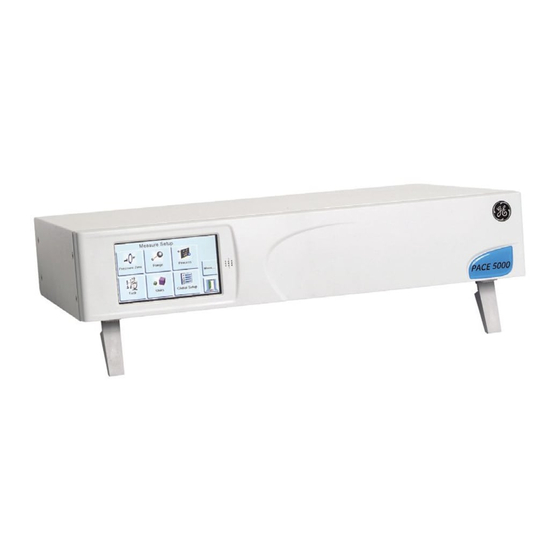
PACE Pressure Controller User Manual Description Introduction The PACE5000 single-channel and PACE6000 single/dual-channel, Pressure Automated Calibration Equipment measures and controls pneumatic pressures and displays, on a touch-screen, the pressure measurement and controller status. The touch-screen enables selections and settings in both measure and control modes. The instrument can be operated remotely through communication interfaces. - Page 12 Figure 1-3 PACE5000 Rear view Figure 1-4 PACE6000 Rear view Options available for the PACE5000 and PACE6000 are detailed in datasheet SDS0001 (PACE5000) and SDS00008 (PACE6000). Further information and notes on applications are available in section 6 of this manual and on the GE Sensing &...
-
Page 13: Installation
PACE Pressure Controller User Manual Installation Packaging On receipt of the PACE5000 or PACE6000 check the contents of the packaging against the following list: Packaging List PACE5000 or PACE6000 Pressure Controller. Cable, power supply. iii) User guide and CD (UD-0001) containing the full documentation suite. -
Page 14: Pneumatic Connections
2 Installation Pneumatic connections WARNINGS: TURN OFF THE SOURCE PRESSURE AND CAREFULLY VENT THE PRESSURE LINES BEFORE DISCONNECTING OR CONNECTING THE PRESSURE LINES. PROCEED WITH CARE. ONLY USE EQUIPMENT WITH THE CORRECT PRESSURE RATING. BEFORE APPLYING PRESSURE, EXAMINE ALL FITTINGS AND EQUIPMENT FOR DAMAGE. REPLACE ALL DAMAGED FITTINGS AND EQUIPMENT. - Page 15 PACE Pressure Controller User Manual Installation The instrument requires a positive pressure supply, instruments operating in an absolute range or negative pressure range require a vacuum supply. A vacuum supply should be used for a fast response for instruments operating near atmospheric pressure. For dual channel operation two independent pressure and vacuum supplies can be used.
- Page 16 2 Installation Pneumatic Connection Examples (Figures 2-2 and 2-4) These examples show a single channel connection detail using supply equipment described above. OUTLET VENT REF SUPPLY ˆ … ‡ † ƒ … ‰ ‚ „ Figure 2-2, Pneumatic Connections without vacuum supply Key to Figure 2-2 Pressure source Conditioner...
- Page 17 PACE Pressure Controller User Manual OUTLET VENT REF SUPPLY ˆ … „ ƒ ‚ ‡ † Š ‰ Š Š ‡ Š Figure 2-3, Pneumatic Connections with vacuum supply Key to Figure 2-3 Pressure source Conditioner Filter Regulate to between 110% full-scale and MWP Diffuser* Unit under test Optional reservoir †...
- Page 18 2 Installation OUTLET VENT REF SUPPLY ˆ … „ ƒ ‚ ‡ † Š ‰ Š ‡ Š Š Figure 2-4, Pneumatic Connections with negative gauge pressure generator Key to Figure 2-4 Pressure source Conditioner Filter Regulate to between 110% full-scale and MWP Diffuser * Unit under test Optional reservoir †...
-
Page 19: Rack-Mount Option
PACE Pressure Controller User Manual Rack-mount option (Figure 2-5) General There must be enough space at the rear of the instrument for all the cables and pipes. The length of the cables and pipes must allow for the removal and fitment of the instrument. The cooling air of the instrument must not be obstructed. -
Page 20: Electrical Connections
2 Installation • Refer to the electrical connections below before finally fitting the instrument into the equipment rack. • Temporarily locate and screw in the two spigots* to each side of the equipment rack. • Locate and slide the instrument into the rack, locating the instrument on the spigots*. •... - Page 21 PACE Pressure Controller User Manual IEC power connector Fuse carrier Fuse Figure 2-6 Electrical Connections Pressure Control Module Input and Output Connectors 24V DC Output @ 100mA maximum Using a 4-way connector: pin “+” +24 Vdc pin “-” 0 Vdc This facility can energise external equipment.
- Page 22 2 Installation Communication Connections Connect the appropriate connectors into the rear panel communications ports and, if appropriate, secure with the captive screws. Note: The RS232 and IEEE 488 interfaces are both enabled at power-up. Set the required parameters in Supervisor Setup/communications menu, see Section 3.8. Figure 2-7, Communication Connectors RS232 Canbus (option)
- Page 23 PACE Pressure Controller User Manual Instrument Control Line Computer/Printer Connector Type Instrument Connector Signal RS232 Function 9-way Direction Terminology D-type 9-way 25-way Pin No. D-type D-type Pin No. Pin No. RxD (I/P) TxD (O/P) CTS (I/P) RTS (O/P) Pulled RLSD high (DCD) internally...
- Page 24 2 Installation IEEE 488 Interface This interface complies with IEEE 488 standard. The IEEE 488 parallel interface connects a computer/controller to one or more PACE instrument and possibly other instruments. Up to 30 instruments can be connected through a high-speed data bus to the computer/controller. Note: The length of each IEEE 488 cable must be less than 3 metres to comply with the EMC requirements, see Section 6 Reference and Specification.
- Page 25 PACE Pressure Controller User Manual Figure 2-8 - IEEE 488 Connection K0443 Issue No. 3 2 - 13...
- Page 26 2 Installation intentionally left blank K0443 Issue No. 3 2 - 14...
-
Page 27: Operation
PACE Pressure Controller User Manual Operation Preparation Make sure the electrical cables and pneumatic pipes comply with the installation requirements in Section 2. Carry out the following before use: • If necessary, carry out the maintenance task detailed in Section 4. •... -
Page 28: Power-Up Sequence
3 Operation Power-up sequence The following sequences of operation show the instrument in measure or control mode. Note:The following sequence is an example, the values and selections displayed depend on the range(s) and options enabled in the instrument. To control pressure, the outlet port must be connected to a UUT or a blanking plug fitted. -
Page 29: Measure Mode
PACE Pressure Controller User Manual Measure mode 1 Pressure measurement of current selected sensor in current selected pressure measurement units 2 Current enabled functions 3 Control/measure selection 4 Nudge up, changed in control set-up 5 Current set-point value, change with numeric keys 6 Nudge down, changed in control set-up 7 Status area, changed in global set-up Display Icons... - Page 30 3 Operation K0443 Issue No. 3 3 - 4...
- Page 31 PACE Pressure Controller User Manual AUTO-RANGE (only available with two-channel instruments) Controller Off – Increasing Set-point With both controllers in Measure mode, if a set-point within the range of the lower ranged controller is entered and Control is then selected the lower ranged controller controls to the entered set-point.
-
Page 32: Control Mode
3 Operation Control Mode In measure mode, press and the instrument changes to control mode. Press and the Control instrument stops controlling pressure and changes to measure mode: Key to display Current measured pressure value (in limits green, out of limits blue). In active control mode. - Page 33 PACE Pressure Controller User Manual Controlling to a new set-point • To change the set-point value, touch the set-point area of the screen and the display shows the numeric keys. Set the new set-point value. • If necessary, use the key to remove the last digit in the set-point value display.
- Page 34 3 Operation K0443 Issue No. 3 3 - 8...
-
Page 35: Operation And Example Procedures
PACE Pressure Controller User Manual Operation and Example Procedures Introduction • Before operation, the instrument must be connected to the correct electrical and pneumatic supplies as detailed in Section 2, Installation. • Switch the instrument ON and, after a short time, the display shows measured pressure mode (except when regulator mode is selected) and to the task set before the power-off. - Page 36 3 Operation Task To control pressure in the task proceed as follows: Select the required units of pressure measurement from the measure set-up menu. Press the status area and enter control set-up, select the required slew rate. The display changes to show the type of slew rate selected. Select the required vent slew rate in vent set-up.
- Page 37 PACE Pressure Controller User Manual Divider Select and set-up the divider task by pressing Divider from the task screen. The divider menu defines high set-point, low set-point and then divides the span into a number of equal test points (min 2, max 25). Divider menu structure Select required units, Rate, etc.
- Page 38 3 Operation Preset The Preset function is similar to the Divider function except that, using this menu, individual set- point values can be defined for each of 25 set-points. The set-up function displays a preset number, pressing the soft key for that number assigns a pressure value to the key.
-
Page 39: Global Set-Up
PACE Pressure Controller User Manual Global Set-up Selections Global set-up selections provide access to the instrument‘s settings for both measure and control modes. This set-up menu provides PIN-protected access to the supervisor set-up and calibration. Pressing Global Set-up from measure or control set-up menu changes the touch-screen display to show five selections, Supervisor Set-up, Calibration, Save/Recall User Set-up and Display. -
Page 40: Barometric Reference Option
3 Operation Status area settings Enables the user to view an operating condition or parameter of the instrument: Full-scale - pressure in current selected units of the pressure range. Source - positive and negative source pressure values in current selected units. Effort meter - indicates controller effort. -
Page 41: Supervisor Set-Up
PACE Pressure Controller User Manual Supervisor set-up K0443 Issue No. 3 3 - 15... -
Page 42: Instrument Status
3 Operation Instrument Status The control set-up menu provides access to the status of the instrument: K0443 Issue No. 3 3 - 16... - Page 43 PACE Pressure Controller User Manual Software Software history, in the status menu, provides read only information on the current software in the instrument. K0443 Issue No. 3 3 - 17...
- Page 44 3 Operation intentionally left blank K0443 Issue No. 3 3 - 18...
-
Page 45: Maintenance
PACE Pressure Controller User Manual Maintenance Introduction This section contains the routine maintenance and procedures to replace components detailed in Section 5, Testing and Fault Finding and listed in Table 4.2. Table 4.1 - Maintenance Tasks Task Period Visual Inspection Daily, before use Cleaning Weekly*... -
Page 46: Replacement Parts
ISOLATE THE INSTRUMENT POWER SUPPLIES BEFORE REPLACING PARTS, WITH POWER APPLIED THE INSTRUMENT CONTAINS LETHAL VOLTAGES. Table 4.2 - Replacement Parts List Part number Description Fuse T2.0A/250V HRC (PACE5000) Fuse T5.0A/250V HRC (PACE6000) IO-FILTER-KIT Kit, filter CMX-XXXX † Module, pressure control refer to data sheet †... - Page 47 PACE Pressure Controller User Manual IEC connector 2 Fuse carrier 3 Fuse Figure 4-1, Power Supply Fuse Replacement K0443 Issue No. 3 4 - 3...
-
Page 48: Filter Replacement
4 Maintenance Filter replacement (Fig 4-2) When necessary change the filters in the pressure module. Note: To gain access to rack-mounted instruments, it will be necessary to completely withdraw the instrument from the rack. Procedure • Switch off instrument. • Depressurize the system and isolate the pneumatic supplies. -
Page 49: Pressure Module Replacement
PACE Pressure Controller User Manual Pressure module replacement (Fig 4-3) WARNING: TURN OFF THE SOURCE PRESSURE AND VENT THE PRESSURE LINES BEFORE DISCONNECTING OR CONNECTING THE PRESSURE LINES. PROCEED WITH CARE. example instrument 1 Pressure module 2 Instrument case 3 Blanking plate Figure 4-3 Pressure module Procedure Note: For rack-mounted units, isolate the electrical power and pneumatic supplies. - Page 50 4 Maintenance • Reconnect the electrical power supply connector. Note: For rack-mounted units, set the power switch to on, locate and secure the instrument in the rack. • Apply the pneumatic pressure and/or vacuum supplies - switch on the electrical power supply.
-
Page 51: Testing And Fault Finding
PACE Pressure Controller User Manual Testing and Fault Finding Introduction • The PACE instrument contains a built-in, self-test and diagnosis system that continuously monitors the performance of the unit. At power-up, the system performs a self-test. • This section details the standard serviceability test. A fault finding table lists possible faults, the probable cause and the procedures to rectify the fault. -
Page 52: Fault Finding
5 Testing and Fault Finding Fault Finding Check the fault conditions and solutions listed in the following table before contacting gesensinginspection.com or a recommended Service Agent. Fault Solution Check rear panel switch set to on. Power supply connected, display not lit. Check fuse and, if necessary, replace Check electrical power supply fuse or circuit breaker. -
Page 53: Approved Service Agents
PACE Pressure Controller User Manual Approved Service Agents For the list of service centres visit our web site: www.gesensinginspection.com K0443 Issue No. 3 5 - 3... - Page 54 5 Testing and Fault Finding intentionally left blank K0443 Issue No. 3 5 - 4...
-
Page 55: Reference And Specification
PACE Pressure Controller User Manual Reference and Specification Installation notes The PACE instrument pressure controller/calibrator requires an independent pressure supply and set of connections with the exception of the reference connection; this provides a reference to atmosphere for gauge sensors and barometric sensors. The instrument must have the correct supply pressure and a suitable supply medium (see data sheet, specification). - Page 56 Reference and Specification Supply contamination Some supplies may need the removal of water, oil or particulate contamination. Any water in the compressed gas supply will be in vapour form, i.e. non-condensing and must be removed using a mist filter. Oil must be completely removed as this causes a rapid deterioration of the control valve performance.
- Page 57 PACE Pressure Controller User Manual Table 6-1 Air Density Values Values of air density (kg m ³) for air of relative humidity 50% and containing 0.04% carbon dioxide by volume. Air temperature (°C) pressure (kPa) 1.052 1.045 1.037 1.029 1.021 1.014 1,006 1.064...
-
Page 58: Operational Requirements
Reference and Specification Operational Requirements Special Note A contaminated UUT must have additional in-line filters connected between the output port and the UUT to prevent contamination of the instrument. Negative or Vacuum Supply The negative supply for absolute control does not need to be regulated. Any variation between this and absolute zero will affect instrument operation if controlling at low absolute pressures. - Page 59 PACE Pressure Controller User Manual Venting Either a zero or vent operation uses the vent port. Vent The system gas at the output pressure can be released from the vent port. Unrestricted gas flow occurs in this operation. Recommended Use a controlled method to reduce the system pressure, at a controlled rate, to near atmospheric pressure then select vent.
-
Page 60: Icons
Reference and Specification Icons Display Icons in Set-up Menus Icon Function Icon Function Icon Function Active Aero mode Airspeed range Alarm Altitude range Area of use Asterisk Auto range Audio volume Auto zero Backlight Calibration Change supervisor Calibration history Canbus Communications Contrast Control mode... - Page 61 PACE Pressure Controller User Manual Icon Function Icon Function Icon Function Exclamation Fault history Gas head pressure Gauge mode Global set-up Go-to-ground Hardware build Home Idle time-out IEEE488 Information In limits Instrument Instrument alias Instrument accuracy name Language Leak test Lock Lock tasks Logic output...
- Page 62 Reference and Specification Icon Function Icon Function Icon Function Restore settings 2 Save as shipped Save recall user Save user set-up Screen mode set-up settings Screen saver SCM filter SCM zero Set-point disable/ Select range Set-point limits enable Set-point higher Set-point lower Set date limit...
-
Page 63: Measure Set-Up
PACE Pressure Controller User Manual Icon Function Icon Function Icon Function Vent time out Vent Yes/No Vent set-up Zero analogue Warning Zero history output Zero Measure Set-up Pressure zero During use, the instrument pressure sensor can show small zero shifts caused by time and temperature changes. -
Page 64: Control Set-Up
Reference and Specification Control Set-up Vent Select Vent to reduce the system pressure to near atmospheric pressure. Use this feature to reduce system pressure to a safe value before disconnecting the Unit Under Test. Use vent set-up to adjust the slew rate of venting. Note: The vent key can be selected in the control set-up menu or programmed as an on-screen selection in the status area from the global set-up/ display/status area menu. -
Page 65: Global Set-Up
PACE Pressure Controller User Manual Global set-up See para. 6.6, not a PIN protected menu. Status The display shows: • Instrument status, model, module, control sensor, +ve source sensor and -ve source sensor • Software build - read only data •... - Page 66 Reference and Specification Supervisor Set-up The Supervisor menu provides facilities for programming settings. These are usually made during installation as follows: Important Note: A PIN protects the Supervisor menu against unauthorised use. Each instrument on delivery contains the factory set PIN (0268). To continue protecting the supervisor set-up menu the PIN should be changed as soon as possible.
- Page 67 PACE Pressure Controller User Manual IEEE 488 Located on the rear panel an external IEEE 488 connection requires: Connector 24-way ‘D’ female wired as IEEE 488 standard Communications IEEE 488 GPIB Default Address Protocols † SCPI, DPI 500, DPI 510, DPI 515, DPI 520 New data up-date rate refer to data sheet Built-in EMC filtering and transient voltage protection.
- Page 68 Confirmation of the new PIN permanently replaces the old PIN. Record this new PIN and keep this record on a safe place. Should this new PIN become lost it can only be reset by returning the instrument to a GE service centre. User defined units Permits the user to define a set of units.
-
Page 69: Options
PACE Pressure Controller User Manual Options Options in the Task Menu The following software enabled options can be selected from the task menu: Leak Test option This task applies one or two test pressures to either an external system to find any leaks in a system connected to the instrument or an internal leak check. - Page 70 Reference and Specification Switch Test option This function automates the testing of pressure switch devices. Connect the pressure port of the switch to be tested to the output port. Connect the switch contacts in series with the 24V dc output and the Logic Input. Note: The volt-free logic input connections require a switching...
- Page 71 PACE Pressure Controller User Manual Test Program option The test program task provides a facility for writing and executing test procedures. Selecting a test program from the Task menu displays all the task programs currently stored, together with the ability to write new ones. K0443 Issue No.
- Page 72 Reference and Specification Program To start a test program, select the test programs listed on the screen, the step function moves down the list of available test programs. To start a test program, press run. When the program starts, a stop legend replaces the run legend. Press the stop key at any time to stop the test program.
- Page 73 PACE Pressure Controller User Manual Example Program Note: Changes to instrument settings made in a test program remain valid only for the test program. The instrument reverts to the pre-test settings on completion. Step Command Argument Action START Program start UNITS mbar Select units, mbar...
- Page 74 Reference and Specification Programming Loops To program a loop, use the GOTO command. Include the COUNT command in the loop for counting the number of loop cycles. Note: The test program commands do not include tests for conditional jumps; to stop a test program from looping, Stop must be selected by the operator.
- Page 75 PACE Pressure Controller User Manual Barometric Reference Option The barometric reference option measures the barometric pressure at the reference port. When installed, this option allows absolute or gauge pressure range selection. To obtain absolute pressure the instrument uses a summation of gauge pressure and barometric pressure (measured by the barometric sensor).
- Page 76 Reference and Specification Aeronautical option The aeronautical option is a specialised application of the PACE instrument. Special application note: The PACE instrument must be set-up very carefully so that the aeronautical pressures applied do not exceed maximum pressure values and rates of change. Leak testing Cautions: Do not exceed the maximum pressures stated in the appropriate Component...
- Page 77 PACE Pressure Controller User Manual Example of Altitude and Airspeed Testing This example shows how two-channel PACE instruments can be used to generate altitude and airspeed. Cautions: Before testing, set the rates of change for both Pitot and Static to a safe value. A high rate of change can damage sensitive aeronautical components.
- Page 78 Reference and Specification In the aeronautical mode, the display goes to the last selected parameter (altitude, airspeed or Mach). Altitude K0443 Issue No. 3 6 - 24...
- Page 79 PACE Pressure Controller User Manual Airspeed Mach K0443 Issue No. 3 6 - 25...
- Page 80 Reference and Specification Analogue Output Option The analogue output option provides a selectable output of voltage or current. Selects Analogue O/P range. analogue connections 30V maximum with On/off respect to chassis Update rate of Analogue O/P option from the control module.
- Page 81 PACE Pressure Controller User Manual Volts-free Contact Option The Volts-free Contact option provides a selectable output of voltage or current. Each selection has three VFC. Volts-free connections Selection of trigger conditions Selection of trigger conditions Volts-free schematic K0443 Issue No. 3 6 - 27...
-
Page 82: Calibration
Changes the Calibration PIN. Enter the existing PIN, the new PIN and confirmation of the new PIN. Should this new PIN become lost it can only be reset by returning the instrument to a GE service centre. Option enable process Use the following process to enable the test program option on a PACE instrument. -
Page 83: 6.10 Communications - Instrument Emulation
The data sheet SDS 0001 or SDS 0008 is contained in the CD shipped with the product. 6.12 Return Goods/Material Procedure Should the unit require calibration or become unserviceable it can be returned to the nearest GE Service Centre listed at gesensinginspection.com. -
Page 84: 6.13 Packaging Procedure
Reference and Specification 6.13 Packaging Procedure The instrument should be at zero/ambient pressure. Set the power switch to off. Shut off the pneumatic pressure and vacuum supplies to the instrument. • Switch off and isolate the electrical power supply to the instrument. Remove the instrument from the equipment rack to access the rear panel. - Page 86 © The General Electric Company. All rights reserved...
Need help?
Do you have a question about the PACE5000 and is the answer not in the manual?
Questions and answers