GE PACE5000 User Manual
Pressure automated calibration equipment
Hide thumbs
Also See for PACE5000:
- Technical manual (176 pages) ,
- Calibration manual (20 pages) ,
- User manual (86 pages)
Table of Contents
Advertisement
GE
Digital Solutions
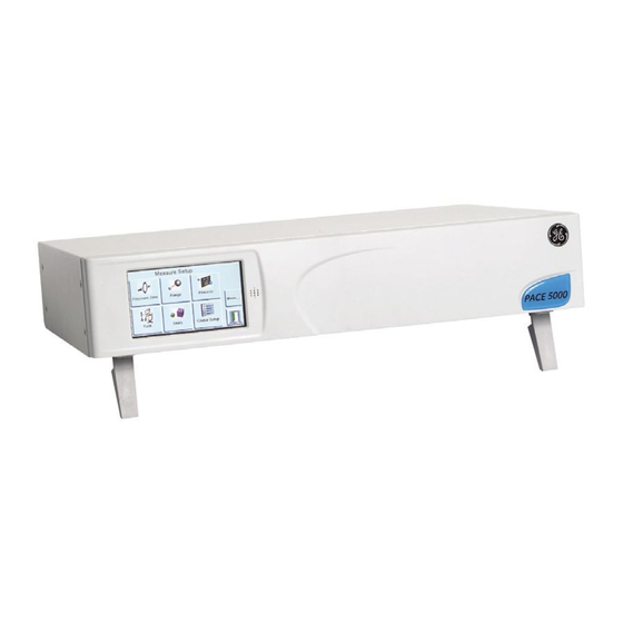
Pressure Automated Calibration Equipment
User manual - K0443 Revision A
PACE5000
PACE6000
© 2008 General Electric Company. All Rights Reserved. Specifications are subject to change
without notice. GE is a registered trademark of General Electric Company. Other company or
product names mentioned in this document may be trademarks or registered trademarks of their
respective companies, which are not affiliated with GE.
Vertrieb für Österreich :
www.nbn.at
nbn Elektronik Handelsgesellschaft m. b. H.
Riesstraße 146, 8010 Graz | Tel. +43 316 40 28 05 | Fax +43 316 40 25 06
Advertisement
Table of Contents

Related Manuals for GE PACE5000


Summary of Contents for GE PACE5000
- Page 1 © 2008 General Electric Company. All Rights Reserved. Specifications are subject to change without notice. GE is a registered trademark of General Electric Company. Other company or product names mentioned in this document may be trademarks or registered trademarks of their respective companies, which are not affiliated with GE.
- Page 2 PACE Pressure Controller User Manual Introduction This manual contains Installation and operating instructions for PACE Pneumatic Pressure Controllers. Safety The manufacturer has designed this equipment to be safe when operated using the procedures detailed in this manual. Do not use this equipment for any other purpose than that stated, the protection provided by the equipment may be impaired.
-
Page 3: Environmental Conditions
Rt MACH Rate of MACH Hertz Receive data Standard commands for Indicated airspeed SCPI programmable instruments IDOS Intelligent digital output sensor (GE product) Sales data sheet Separated (or Safety) extra low i.e. That is SELV voltage Institute of Electrical and Electronic Engineers standard... - Page 4 PACE Pressure Controller User Manual Related publications K0447 PACE 5000/6000 User Guide and Safety Instructions K0450 PACE Series Calibration Manual K0476 Pressure Control Module User Guide and Safety Instructions K0472 Remote Communications Manual K0469 Heritage Communications Manual - Instrument Emulation Symbols This equipment meets the requirements of all relevant European safety directives.
- Page 5 WARNINGS TURN OFF THE SOURCE PRESSURE(S) AND CAREFULLY VENT THE PRESSURE LINES BEFORE DISCONNECTING OR CONNECTING THE PRESSURE LINES. PROCEED WITH CARE. ONLY USE EQUIPMENT WITH THE CORRECT PRESSURE RATING. BEFORE APPLYING PRESSURE, EXAMINE ALL FITTINGS AND EQUIPMENT FOR DAMAGE. REPLACE ALL DAMAGED FITTINGS AND EQUIPMENT.
- Page 6 PACE Pressure Controller User Manual Pressure units and conversion factors Pressure units Factor (hPa) Pressure units Factor (hPa) O @ 20°C mbar 0.978903642 O @ 20°C 1000.0 97.8903642 0.01 0.0980665 Pa (N/m kg/m 980.665 kg/cm 10.0 torr 1.333223684 10000.0 1013.25 mmHg @ 0°C 1.333223874 68.94757293...
-
Page 7: Table Of Contents
CONTENTS Section Title Page Description Introduction Installation Packaging Packaging for Storage and Transportation Preparation for Use Pneumatic connections Rack-mount option Electrical connections OPERATION Preparation Power-up Sequence Measure Mode Control Mode Operation and Example Procedures 3-10 Global Set-up Selections 3-14 Barometric Reference Option 3-15 Supervisor Set-up 3-16... -
Page 8: Table Of Contents
PACE Pressure Controller User Manual Cleaning Test Calibration Replacement parts Fuse replacement Filter replacement Pressure module replacement TESTING AND FAULT FINDING Introduction Standard Serviceability Test Fault Finding Approved Service Agents REFERENCE AND SPECIFICATION Installation notes Operational Requirements Icons Measure Set-up Control Set-up 6-10 Global Set-up... - Page 9 6.14 Vacuum System Parts 6-43 K0443 Revision A viii [EN] English...
-
Page 10: Description
PACE Pressure Controller User Manual Description Introduction The PACE5000 single-channel and PACE6000 single/dual-channel, Pressure Automated Calibration Equipment measures and controls pneumatic pressures and displays, on a touch-screen, the pressure measurement and controller status. The touch-screen enables selections and settings in both measure and control modes. The instrument can be operated remotely through communication interfaces. - Page 11 1 Description Figure 1-3 PACE5000 Rear view Figure 1-4 PACE6000 Rear view Options available are detailed in the product datasheet. Information and notes on applications (Ref: Reference and Specification, Section 6) www.gemeasurement.com K0443 Revision A 1 - 2 [EN] English...
-
Page 12: Installation
PACE Pressure Controller User Manual Installation Packaging Check the contents of the PACE5000/6000 packaging with the list that follows: Packaging List PACE5000 or PACE6000 Pressure Controller. Cable, power supply. iii) User guide and CD (UD-0001) containing the full documentation suite. -
Page 13: Pneumatic Connections
2 Installation Pneumatic connections WARNINGS TURN OFF THE SOURCE PRESSURE(S) AND CAREFULLY VENT THE PRESSURE LINES BEFORE DISCONNECTING OR CONNECTING THE PRESSURE LINES. PROCEED WITH CARE. ONLY USE EQUIPMENT WITH THE CORRECT PRESSURE RATING. BEFORE APPLYING PRESSURE, EXAMINE ALL FITTINGS AND EQUIPMENT FOR DAMAGE. REPLACE ALL DAMAGED FITTINGS AND EQUIPMENT. - Page 14 PACE Pressure Controller User Manual Connection Port supply + Input ISO228/1 G 1/8 parallel threads (DIN ISO228/1, JIS B0202) supply - Output Output Vent ISO228/1 G 1/8 parallel threads (DIN ISO228/1, JIS B0202) Reference Refer to the data sheet for a complete range of adaptors. Pressure supply (Ref: Figure 2-1, Pneumatic connections) The pressure supply must be clean, dry gas, nitrogen or air and at the correct pressure,...
- Page 15 2 Installation Installation The safety of any system incorporating the equipment is the responsibility of the assembler of the system. The instrument requires a positive pressure supply, instruments operating in an absolute range or negative pressure range require a vacuum supply. A vacuum supply should be used for a fast response for instruments operating near atmospheric pressure.
- Page 16 PACE Pressure Controller User Manual Supply equipment Pneumatic supplies should have isolation valves and, where necessary, conditioning equipment. The positive pressure supply should be regulated to between 110% of the full-scale pressure range and MWP stated on the control module. To protect the instrument from over-pressure a suitable protection device (such as a relief valve or bursting disc) must be fitted to prevent over pressurization.
- Page 17 2 Installation Note: (Ref: Section 6, Reference and Specification) for details of other system components. SUPPLY OUTPUT VENT REF Figure 2-4, Pneumatic Connections with vacuum supply 1) Pressure source 2) Conditioner 3) Filter 4) Regulate to between 110% full-scale and MWP 5) Diffuser* 6) Unit under test 7) Optional reservoir †...
- Page 18 PACE Pressure Controller User Manual SUPPLY OUTPUT VENT REF Figure 2-5, Pneumatic Connections with negative gauge pressure generator 1) Pressure source 2) Conditioner 3) Filter 4) Regulate to between 110% full-scale and MWP 5) Diffuser * 6) Unit under test 7) Optional reservoir †...
-
Page 19: Rack-Mount Option
2 Installation Rack-mount option (Ref: Figure 2-6) General There must be enough space at the rear of the instrument for all the cables and pipes. The length of the cables and pipes must allow for the removal and fitment of the instrument. The cooling air of the instrument must not be obstructed. -
Page 20: Electrical Connections
PACE Pressure Controller User Manual Procedure . Locate bracket in rack assembly Remove the four M3x10mm countersunk screws from each of the instrument side panels. Locate the two brackets on each side of the instrument. Secure with the four countersunk screws. Support the instrument and connect the cables and pipes. - Page 21 2 Installation 1 IEC power connector 2 Fuse carrier 3 Fuse Figure 2-7 Electrical Connections Pressure Control Module Input and Output Connectors 24V DC Output @ 100mA maximum 4-way connector: pin “+” = +24 Vdc pin “-” 0 Vdc An integral self-resetting fuse protects this output. Logic (switch) Input 4-way connector: Input Output...
- Page 22 PACE Pressure Controller User Manual Communication Connections (Ref: Fig 2-8 Communication Connectors) Connect the applicable connectors into the rear panel communications ports and, if appropriate, secure with the captive screws. Note: Refer to the data sheet for a list of optional communication ports. Refer to the data sheet for a list of standard shipped communication ports.
- Page 23 2 Installation RS232 Interface When using the RS232 interface, a cable must be connected directly from the instrument to a suitable port on the computer in a ‘point to point’ link. The pin connections for the 9-pin D- type, RS232 connector and the relationship between the instrument and the RS232 control signals, together with device interconnection interface is shown in Table 2-1.
- Page 24 PACE Pressure Controller User Manual IEEE 488 Interface The interface complies with IEEE 488 standard. The IEEE 488 parallel interface connects a computer/controller to one or more PACE instruments and other instruments. Up to 30 instruments can be connected through a high-speed data bus to the computer/ controller.
- Page 25 2 Installation Figure 2-9 - IEEE 488 Connection K0443 Revision A 2 - 14 [EN] English...
-
Page 26: Operation
PACE Pressure Controller User Manual Operation This section contains quick reference charts detailing all the available functions and the set- up menu. Preparation Make sure the electrical cables and pneumatic pipes comply with the installation requirements (Ref: Section 2, Installation). Before use do the following: If necessary, do the maintenance task (Ref: Section 4,... -
Page 27: Power-Up Sequence
3 Operation Power-up sequence The following sequences of operation shows the instrument display. Note: The following sequence is an example, the values and selections displayed depend on the range(s) and options enabled in the instrument (Ref: Touch screen areas). Set the power supply to ON: The display shows the power-up sequence. -
Page 28: Measure Mode
PACE Pressure Controller User Manual Measure mode PACE5000 PACE6000 Pressure measurement of current selected sensor in current selected pressure measurement units Current enabled functions Control/measure selection Nudge up, changed in control set-up Current set-point value, change with numeric keys Nudge down, changed in control set-up... - Page 29 3 Operation PACE5000 Measure set-up Pressure zero current pressure reading to zero, offset stored for current range. Range allows selection of available pressure ranges. PACE6000 Process Filter pressure reading Tare Task Units select from list of available pressure measurement units.
- Page 30 PACE Pressure Controller User Manual AUTO-RANGE (only available with two-channel instruments) Note: Not all Auto-Range and task functions are available using the remote communications, this allows more flexibility to the remote programmer. Controller Off – Increasing Set-point With both controllers in Measure mode, if a set-point within the range of the lower ranged controller is entered and Control is then selected the lower ranged controller controls to the entered set-point.
-
Page 31: Control Mode
3 Operation Module 2 Module 1 Rear view of SUPPLY OUTLET VENT SUPPLY OUTLET VENT PACE6000 instrument Pressure output Pressure Pressure regulator regulator Pressure source Control Mode In measure mode, press and the instrument changes to control mode. Control Press and the instrument stops controlling pressure and changes to measure mode: Measure Key to display:... - Page 32 PACE Pressure Controller User Manual Tare enabled. Press to switch between controlled pressure and measured pressure. Nudge up. Set-point, press and the display changes to numeric keys. Nudge down. Status area shows effort meter set in global set-up, press to enter control set-up. Notes: Active mode - control active, except in measure mode.
- Page 33 3 Operation point. The status area can be changed to various displays showing pressure and controller performance. Effort meter Note: In normal controlled pressure conditions the effort meter stays within the band (green). If the status indicator moves outside the band there may be a leak into or out of the system.
- Page 34 PACE Pressure Controller User Manual Control set-up Vent Yes/No Sets set-point Nudge resolution nudge resoultion. to 7 digit. Upper Set-point limits Lower Enable/disable Linear - Enter units/second Slew rate Maximum rate Toggle between: fast/no overshoot Active - Continuous control to set-point Control mode Passive - Controls outside user defined band Gauge - Controls from zero gauge to set-point...
-
Page 35: Operation And Example Procedures
3 Operation Operation and Example Procedures Introduction Before operation, the instrument must be connected to the correct electrical and pneumatic supplies (Ref: Section 2, Installation). Switch the instrument ON, the display shows measured pressure mode (except when regulator mode is selected) and the task set before the power-off. Measure and Control Modes The instrument operates in the two modes that follow: •... - Page 36 PACE Pressure Controller User Manual Task To control pressure in the task do the following: Select the required units of pressure measurement from the measure set-up menu. Press the status area and enter control set-up. Select the required slew rate. Note: The display changes to show the type of slew rate selected.
- Page 37 3 Operation Divider Select and set-up the divider task by Divider pressing Divider from the task screen. The divider menu specifies high set-point, low set-point and then divides the span into a number of equal test points (min 2, max 25). Divider Divide as set-up.
- Page 38 PACE Pressure Controller User Manual Preset The Preset function allows individual set-point values Preset can be defined for each of 25 set-points. The set-up function displays Preset Preset as set-up a preset number. Pressing the soft key for that Set-up number assigns a pressure value to the key.
-
Page 39: Global Set-Up Selections
3 Operation Global Set-up Selections Global set-up selections provide access to the instrument‘s settings for both measure and control modes. The set-up menu that follows provides PIN-protected access to the supervisor set-up and calibration. Pressing Global Set-up from measure or control set-up menu changes the touch-screen display to show the following selections: •... -
Page 40: Barometric Reference Option
PACE Pressure Controller User Manual Status area settings Enables the user to view an operating condition or parameter of the instrument: Full-scale - pressure in current selected units of the pressure range. Source - positive and negative source pressure values in current selected units. Effort meter - indicates controller effort. -
Page 41: Supervisor Set-Up
3 Operation Supervisor set-up Supervisor Pressing the escape key stores settings and returns to global set-up. enter four digit code (0268) Protective Vent Enable/disable % full-scale In Limits Time period - time to stay in limits before trigger indication High source pressure Low source pressure Alarms Enable/disable high pressure... -
Page 42: Instrument Status
Module (2) Boot ROM * current settings, see 6.7 Zero Current set-up In Limits High Alarm Low Alarm Slew Rate Power Up PACE5000 Operation time* Use log Control time* * days, hours and minutes More next page: Use log [EN] English... - Page 43 3 Operation Software Software history, in the status menu, provides read only information on the current software in the instrument. Software history Instrument Main Code Instrument OS Build Instrument Boot ROM Example Module (1) Main Code Module (1) Boot ROM Analogue O/P Main Code More next page:...
-
Page 44: Maintenance
Inspect for obvious signs of damage and dirt on the following: a.External of the instrument. b.Power supply connector and power lead. c.Associated equipment. Damaged parts must be replaced contact GE Service. Cleaning Caution Do not use solvents for cleaning. Clean the front panel with a damp lint-free cloth and mild detergent. -
Page 45: Calibration
DISCONNECTING THE PRESSURE LINES FOR MAINTENANCE. PROCEED WITH CARE. ISOLATE THE INSTRUMENT POWER SUPPLIES BEFORE REPLACING PARTS, WITH POWER APPLIED THE INSTRUMENT CONTAINS LETHAL VOLTAGES. Table 4.2 - Replacement Parts List Part number Description Fuse T2AH250V (PACE5000) Fuse T5AH250V (PACE6000) IO-FILTER-KIT Kit, filter CMX-XXXX † Module, pressure control refer to data sheet †... - Page 46 PACE Pressure Controller User Manual Replace 1. Check for the correct type of fuse (Ref: Table 4.2 Replacement Parts List). 2. Replace the fuse. 3. Refit the fuse carrier (2) in the power supply inlet socket assembly. 4. Refit and reconnect rack-mounted units (Ref: Installation, Section 5.
-
Page 47: Filter Replacement
4 Maintenance Filter replacement (Ref: Figure 4-2, Pressure module filters) Remove 1. Set the power switch to OFF (if not rack-mounted got to step 3). 2. For access to rack-mounted instruments, completely withdraw the instrument from the rack. 3. Depressurize the system and isolate the pneumatic supplies. 4. -
Page 48: Pressure Module Replacement
PACE Pressure Controller User Manual Pressure module replacement (Ref: Figure 4-3, Pressure module) WARNING TURN OFF THE SOURCE PRESSURE AND VENT THE PRESSURE LINES BEFORE DISCONNECTING OR CONNECTING THE PRESSURE LINES. PROCEED WITH CARE. 1 - Pressure module 2 - Instrument case 3 - Blanking plate Figure 4-3 Pressure module Remove... - Page 49 4 Maintenance Intentionally Blank K0443 Revision A 4 - 6 [EN] English...
- Page 50 PACE Pressure Controller User Manual Testing and Fault Finding Introduction This section details the standard serviceability test. (Ref: Fault Diagnosis, Table 5.1) possible faults, and the response. The PACE instrument contains a self-test and diagnosis system that continuously monitors the performance of the unit. At power-up, the system performs a self-test. Standard Serviceability Test The following procedure shows if the unit is serviceable and checks functions and facilities of the PACE instrument.
- Page 51 5 Testing and Fault Finding When the controller achieves the selected pressure set-point, the screen display changes as follows: The colour of the displayed pressure value changes from blue to green indicating that the controller is within the in-limits tolerance. If enabled, the effort meter shows the controller effort to keep the pressure at the set-point.
-
Page 52: Approved Service Agents
Fault Finding Check the faults and responses (Ref: Fault Diagnosis, Table 5.1) before contacting www.gemeasurement.com or a GE recommended Service Agent Fault Response Power supply connected, display not lit. Check rear panel switch set to on. Check fuse and, if necessary, replace Check electrical power supply fuse or circuit breaker. - Page 53 5 Testing and Fault Finding Intentionally Blank K0443 Revision A 5 - 4 [EN] English...
-
Page 54: Reference And Specification
PACE Pressure Controller User Manual Reference and Specification Installation notes The PACE instrument pressure controller/calibrator requires an independent pressure supply and set of connections. The exception is the reference connection, this provides a reference to atmosphere for gauge sensors and barometric sensors. The instrument must have the correct supply pressure and a suitable supply medium (Ref: Data sheet, specification). - Page 55 6 Reference and Specification Supply contamination Supplies may need the removal of water, oil or particulate contamination. Any water in the compressed gas supply will be in vapour form, i.e. non-condensing and must be removed using a mist filter. Oil must be completely removed as this causes a rapid deterioration of the control valve performance.
- Page 56 PACE Pressure Controller User Manual Table 6-1 Air Density Values Values of air density (kg m ) for air of relative humidity 50% and containing 0.04% carbon dioxide by volume. Air temperature (°C) pressure (kPa) 1.052 1.045 1.037 1.029 1.021 1.014 1,006 1.064...
-
Page 57: Operational Requirements
6 Reference and Specification Operational Requirements Caution A contaminated UUT must have additional in-line filters connected between the output port and the UUT to prevent contamination of the instrument. Negative or Vacuum Supply The negative supply for absolute control does not need to be regulated. Any variation between this and absolute zero will affect instrument operation if controlling at low absolute pressures. - Page 58 PACE Pressure Controller User Manual Venting Either a zero or vent operation uses the vent port. Vent The system gas at the output pressure can be released from the vent port. Unrestricted gas flow occurs in this operation. Recommended Use a controlled method to reduce the system pressure, at a controlled rate, to near atmospheric pressure then select vent.
-
Page 59: Icons
6 Reference and Specification Icons Display Icons in Set-up Menus Icon Function Icon Function Icon Function Active Aero mode Airspeed range Alarm Altitude range Area of use Asterisk Auto range Audio volume Auto zero Backlight Calibration Change supervisor Calibration history Communications Contrast Control mode... - Page 60 PACE Pressure Controller User Manual Icon Function Icon Function Icon Function Exclamation Fault history Gas head pressure Gauge mode Global set-up Go-to-ground Hardware build Home Idle time-out IEEE488 Information In limits Instrument Instrument alias Instrument accuracy name Language Leak test Lock Lock tasks Logic output...
- Page 61 6 Reference and Specification Icon Function Icon Function Icon Function Restore settings 2 Save as shipped Save recall user Save user set-up Screen mode set-up settings Screen saver SCM filter SCM zero Set-point disable/ Select range Set-point limits enable Set-point higher Set-point lower Set date limit...
-
Page 62: Measure Set-Up
PACE Pressure Controller User Manual Icon Function Icon Function Icon Function Vent time out Vent Yes/No Vent set-up Zero analogue Warning Zero history output Zero Measure Set-up Pressure zero During use, the instrument pressure sensor can show small zero shifts caused by time and temperature changes. -
Page 63: Control Set-Up
6 Reference and Specification Control Set-up Vent Select Vent to reduce the system pressure to near atmospheric pressure. Use this feature to reduce system pressure to a safe value before disconnecting the UUT. Use vent set-up to adjust the slew rate of venting. Note: The vent key can be selected in the control set-up menu or programmed as an on- screen selection in the status area from the global set-up/ display/status area menu. -
Page 64: Global Set-Up
PACE Pressure Controller User Manual Global set-up PIN protected menu (Ref: Supervisor set-up, Section 6.7). Status The display shows the following: Instrument • Module 1 (Module2 if fitted) • Control sensor • +ve source sensor • -ve source sensor • Barometric sensor (Optional) Software build - read only data Hardware build - read only data... - Page 65 6 Reference and Specification Supervisor Set-up The Supervisor menu provides facilities for programming settings. These are made during installation as follows: Important Note: A PIN protects the Supervisor menu against unauthorised use. Each instrument on delivery contains the factory set PIN (0268). To continue protecting the supervisor set-up menu the PIN should be changed as soon as possible.
- Page 66 PACE Pressure Controller User Manual RS232 Located on the rear panel an external RS232 connection requires the following: Connector 9-way ‘D’ female wired as per Table 2-1 Communications RS232 point-to-point only (DPI 520 daisy chain is not supported) Baud Rate power-up default 9600, no parity &...
- Page 67 6 Reference and Specification Ethernet Firewall A firewall protects the Ethernet connection. The firewall is always turned on. The following ports are unfiltered to allow remote communication and control. Port Description 80/tcp http (Web server) 111/tcp rpcbind (RPC for VXI) 111/udp rpcbind (RPC for VXI) 443/tcp...
- Page 68 Note: The factory set Supervisor PIN is 0268. If the Supervisor PIN has been locally changed, make sure that the new PIN is kept in a safe place. If the new PIN is lost, it can only be reset at a GE Service Centre. [EN] English...
- Page 69 6 Reference and Specification 5. Press COMMUNICATIONS STATUS to open the COMMUNICATIONS STATUS screen. 6. Select ETHERNET to open the ETHERNET PARAMETER screen. 7. To change the ADDRESS parameter, complete the following: a. On the ETHERNET PARAMETER screen, use the UP and DOWN arrows to highlight the ADDRESS field.
- Page 70 PACE Pressure Controller User Manual c. Use the UP and Down arrows to highlight the desired address type (either AUTO IP or STATIC). d. Press the top touch pad on the screen to set the new address type. The screen automatically returns to the ETHERNET PARAMETERS screen.
- Page 71 6 Reference and Specification 9. To change the web password, complete the following: a. On the ETHERNET PARAMETER screen, use the UP and DOWN arrows on the right of the screen to highlight the WEB PASWORD field. b. Press the top touch pad on the screen to enter the WEB PASSWORD screen. The keyboard screen opens.
- Page 72 PACE Pressure Controller User Manual c. Use the keyboard to input the new web password and then press the top touch area on the screen to set the new password. The screen automatically returns to the ETHERNET PARAMETERS screen. 10. To reset the LAN settings, complete the following: a.
- Page 73 6 Reference and Specification Located on the rear panel a USB connection requires the following: Connector USB ‘B’ Protocol SCPI Terminator CR, LR or CR/LF Communications mode is selected for serial communications using the SCPI protocol. Mass storage device is selected to mount an external USB ‘A’ connected mass storage device or the internal memory SD card, from a PC connected to the USB ‘B’...
- Page 74 Note: Confirmation of the new PIN permanently replaces the old PIN. Record this new PIN and keep in a safe place. If new PIN is lost it can only be reset by returning the instrument to a GE service centre. User defined units Permits the user to define a set of pressure conversion units.
- Page 75 Create a language file by translating from the English language file. Check the pixel width of each translated word by using the PACE language check file, (download from GE Support Central PACE). Create an empty DPI folder on a USB stick.
- Page 76 PACE Pressure Controller User Manual Figure 1 Language Setting Restore as shipped settings Restores instrument settings to factory default, but does not affect PIN settings. [EN] English 6 - 23 K0443 Revision A...
-
Page 77: Options
6 Reference and Specification Options Option enable process To enable soft options on a PACE instrument, use the following: Touch the top Measure area of the screen. Select Global Setup. Select Calibration. Serial number Enter a Calibration PIN 1234. Enter new option key xxxxxxxxxx (10 digits). - Page 78 PACE Pressure Controller User Manual Note: If only one test pressure Leak test is required set TP1 = TP2. At the start of the test, the Start instrument applies a test Example set-up parameter pressure to the user system. Set-up A control dwell time allows the user system to thermally Test pressure 1...
- Page 79 6 Reference and Specification Switch Test option This function automates the testing of Switch test pressure switch devices. Connect the Start pressure port of the switch to be tested to Switch test the output port. Connect the switch Stop contacts in series with the 24V dc output and the Logic Input.
- Page 80 PACE Pressure Controller User Manual Test Program option The test program task provides a facility for writing and executing test procedures. Selecting a test program from the Task menu displays all the task programs currently stored, together with the ability to write new ones. Test program Start Stop...
- Page 81 6 Reference and Specification Program To start a test program do the following: Select the test programs listed on the screen. The step function moves down the list of available test programs. To start a test program, press run. When the program starts, a stop legend replaces the run legend. Press the stop key at any time to stop the test program.
- Page 82 PACE Pressure Controller User Manual Table 6-2 - Test Program Commands Command Description BEEP Beep on/off. Breaks to this point when stop count command or STOP icon is selected, then BREAK executing code to the end. CONTROL Selects Control mode. COUNT Used in a loop to count the number of loop cycles.
- Page 83 6 Reference and Specification Example Program Note: Changes to instrument settings made in a test program remain valid only for the test program. The instrument reverts to the pre-test settings on completion. Step Command Argument Action START Program start UNITS mbar Select units, mbar RATE...
- Page 84 PACE Pressure Controller User Manual Programming Loops To program a loop, use the GOTO command. Include the COUNT command in the loop for counting the number of loop cycles. Note: The test program commands do not include tests for conditional jumps. To stop a test program from looping, STOP must be selected by the operator.
- Page 85 6 Reference and Specification Barometric Reference Option The barometric reference option measures the barometric pressure at the reference port. When installed, this option allows absolute or gauge pressure range selection. To obtain absolute pressure the instrument uses a summation of gauge pressure and barometric pressure (measured by the barometric sensor).
- Page 86 PACE Pressure Controller User Manual Aeronautical option The aeronautical option is a specialised application of the PACE instrument. Special application note: The PACE instrument must be set-up very carefully so that the aeronautical pressures applied do not exceed maximum pressure values and rates of change.
- Page 87 6 Reference and Specification Altitude to Airspeed. Module 2 Module 1 Module 2 Module 1 SUPPLY OUTLET VENT SUPPLY OUTLET VENT SUPPLY OUTLET VENT SUPPLY OUTLET VENT Rear view of instrument Open to Atmosphere Rear view of instrument Altimeter ASI/Mach Pitot Static Example of Altitude and Airspeed Testing...
- Page 88 PACE Pressure Controller User Manual Pitot Static (Altitude) Module 2 Module 1 Rear view of SUPPLY OUTLET VENT SUPPLY OUTLET VENT PACE instrument Static Static Altimeter ASI/Mach Pitot Pressure Pressure regulator regulator Pressure source Vacuum source Units The units can be either the aeronautical or pressure units. The units can be changed any time between pressure and pressure converted to aeronautical units.
- Page 89 6 Reference and Specification Control of Aeronautical parameters The aeronautical control is an intergrated controller. The two modules work together as a dual channel pressure controller (Ref: Figure 1, Screen Layout). In aeronautical mode, the display goes to the last selected parameter: •...
- Page 90 PACE Pressure Controller User Manual Figure 1 Screen Layout In dual screen mode both altitude and airspeed controllers are set to control mode, by selecting the Enter Control key (Ref: Figure 1, Screen Layout). The Enter Measure key sets both controllers to measure mode. (Ref: Figure 1, Screen Layout).
- Page 91 6 Reference and Specification (Ref: Figure 2, measurement mode) both controllers in measurement mode. Figure 3 Control mode (Ref: Figure 3, Control mode) both controllers in control mode. In control mode each control can have an individual set-point. If Hold is selected (Ref: Figure 3, Item 1, Control mode) a set altitude or speed will be held.
- Page 92 PACE Pressure Controller User Manual Analogue Output Option The analogue output option provides a selectable output of voltage or current. Selects Analogue Output Range analogue connections 30V maximum with respect to chassis. On/Off Rated output = 24V To maintain PACE product safety, external circuits connected to the instrument must meet Safety Extra-Low Voltage (SELV) requirements.
- Page 93 6 Reference and Specification Volts-free Contact Option The Volts-free Contact option provides a selectable output of voltage or current. Each selection has three Volts-free Contacts. volts-free connections 30V maximum with respect to chassis. Rated output = 24V Selection of trigger To maintain PACE product safety, external conditions.
- Page 94 Note: Data sheet 920-561 is contained in the CD shipped with the product. 6.12 Return Goods/Material Procedure If the unit requires calibration or is unserviceable return it to the nearest GE Service Centre listed at www.gemeasurement.com. Contact the Service Department, by 'phone, fax or E-mail to obtain a Return Goods Authorisation (RGA) (Worldwide excluding USA).
-
Page 95: Packaging Procedure
6 Reference and Specification Safety Precautions You must inform GE if the product has been in contact with any hazardous or toxic substance. The relevant COSHH or in the USA, MSDS, references and precautions to be taken when handling. Important notice Service or calibration by unauthorized sources will affect the warranty and may not guarantee further performance. - Page 96 PACE Pressure Controller User Manual 6.14 Vacuum System Parts The parts list below lists a typical system to supply vacuum, enabling the control of sub- atmospheric pressures by the PACE instrument. Part numbers quoted in the table are taken from the BOC Edwards Vacuum Products Catalogue. For more information, go to: www.bocedwards.com.
- Page 97 6 Reference and Specification Intentionally Blank K0443 Revision A 6 - 44 [EN] English...
- Page 98 www.gemeasurement.com Vertrieb für Österreich : nbn Elektronik Handelsgesellschaft m. b. H. www.nbn.at Riesstraße 146, 8010 Graz | Tel. +43 316 40 28 05 | Fax +43 316 40 25 06...
Need help?
Do you have a question about the PACE5000 and is the answer not in the manual?
Questions and answers