
Related Manuals for VIA Technologies EPIA-M930


Summary of Contents for VIA Technologies EPIA-M930
- Page 1 USER MANUAL VIA EPIA-M930 Highly-integrated low-power platform with rich feature set and multimedia capabilities 1.00-06092022...
- Page 2 VIA Technologies, Inc. reserves the right the make changes to the products described in this manual at any time without prior notice.
- Page 3 VIA EPIA-M930 User Manual Battery Recycling and Disposal • Only use the appropriate battery specified for this product. • Do not re-use, recharge, or reheat an old battery. • Do not attempt to force open the battery. • Do not discard used batteries with regular trash.
- Page 4 VIA EPIA-M930 User Manual Box Contents EPIA-M930 SKU • 1 x VIA EPIA-M930 board • 1 x SATA cable • 1 x SATA power cable • 1 x I/O bracket • 1 x M.2 screw pack (2 screws + 1 standoff)
- Page 5 VIA EPIA-M930 User Manual Revision History Revision Date Description 1.00 21/09/2022 Initial release...
-
Page 6: Table Of Contents
VIA EPIA-M930 User Manual Table of Contents Product Overview ............................1 Key Features & Benefits ........................1 1.1.1 Intel Celeron Quad Core Processor ....................1 1.1.2 Modular Expansion Options ......................1 Product Specifications ........................... 1 Layout Diagram ............................. 3 Product Dimensions ..........................5 Height Distribution .......................... - Page 7 Installing the VIA EMIO-8570 4G LTE & GPS M.2 Module Kit .............. 52 Installing the M.2 SATA SSD ......................... 53 Appendix B Power Consumption Report ......................54 VIA EPIA-M930 Rev. 1.......................... 54 B.1.1 IDLE Status ........................... 54 B.1.2 S3 Status ............................54 B.1.3...
- Page 8 List of Figures Figure 01: VIA EPIA-M930 board layout (top view) ....................3 Figure 02: Mounting holes and dimensions of the VIA EPIA-M930 ............... 5 Figure 03: External I/O port dimensions of the VIA EPIA-M930 ................5 Figure 04: Height distribution of the VIA EPIA-M930 .................... 6 Figure 05: Back panel I/O ports ..........................
- Page 9 VIA EPIA-M930 User Manual Figure 57: Illustration of the PCH-IO Configuration screen ................. 43 Figure 58: Illustration of the SATA Configuration screen ..................44 Figure 59: Illustration of the HD Audio Configuration screen ................45 Figure 60: Illustration of the Security Settings screen ..................45 Figure 61: Illustration of the Boot Settings screen ....................
- Page 10 VIA EPIA-M930 User Manual List of Tables Table 01: Description table of the VIA EPIA-M930 board layout ................. 4 Table 02: Layout diagram description table of the back panel I/O ports ............. 7 Table 03: HDMI® port pinouts ..........................8 Table 04: COM port pinouts ..........................
-
Page 11: Product Overview
It can also be used for various domain applications such as desktop PC, industrial PC, etc. The VIA EPIA-M930 is based on the Intel Celeron Quad Core Processor that features the Integrated Intel Graphics gen 11-Lower Power (Gen 11-LP) for rich digital media performance. - Page 12 VIA EPIA-M930 User Manual Graphics • Integrated Intel Graphics Gen 11-Low Power (GEN 11-LP) • Supports OpenCL*1.2, OpenGL 4.5, OpenGL-ES 3.2, Vulkan. V1.1, DirectX • Realtek-RTL8111H-CG Gigabit Ethernet controller Audio • Realtek ALC8888S-VD2-GR High Definition Audio Codec Super I/O •...
-
Page 13: Layout Diagram
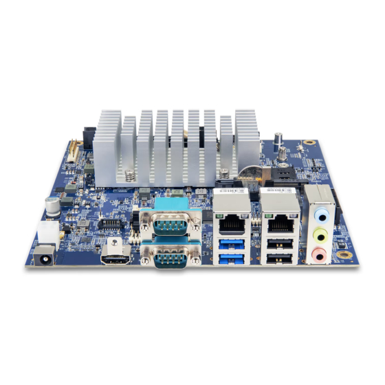
It is highly recommended to execute a solid testing program and take all variables into consideration when building the system. Please ensure that the system is stable at the required operating temperature in terms of application. 1.3 Layout Diagram Figure 01: VIA EPIA-M930 board layout (top view) -
Page 14: Table 01: Description Table Of The Via Epia-M930 Board Layout
GPIO Pin Header (DIO1) Giga LAN & USB3.0 Connector (GLAN1) COM3,4 Voltage Select pin header(COMH_S1) COM4 Pin Header (COMH2) COM Port Connector (Up: COM1, Down: COM2) COM3 Pin Header (COMH1) HDMI2 Connector (HDMI2) Table 01: Description table of the VIA EPIA-M930 board layout... -
Page 15: Product Dimensions
170mm 33.0mm 132.1mm 4.9mm 6.4mm 6.4mm 157.4mm 170mm 6.2mm 6.2mm 154.9mm 10.2mm 4.9mm Figure 02: Mounting holes and dimensions of the VIA EPIA-M930 210.17mm 29.11mm 17.19mm 199.17mm 10.09mm 188.17mm 7.31mm Figure 03: External I/O port dimensions of the VIA EPIA-M930... -
Page 16: Height Distribution
VIA EPIA-M930 User Manual 1.5 Height Distribution 7.4mm 16.2mm 33.4mm 32mm 31.8mm 31mm 35.5mm 100mm Figure 04: Height distribution of the VIA EPIA-M930... -
Page 17: I/O Interface
VIA EPIA-M930 User Manual 2. I/O Interface The VIA EPIA-M930 has a wide selection of interfaces, and includes a selection of frequently used ports as part of the external I/O coastline. 2.1 External I/O Ports Figure 05: Back panel I/O ports... -
Page 18: Com Ports
VIA EPIA-M930 User Manual Signal Signal TX2+ TX2- TX1+ TX1- TX0+ TX0- 10 TXC+ 11 GND 12 TXC- 13 key 14 key 15 DDCSCL 16 DDCSDA 17 GND 18 +5V 19 Hot Plug Detect Table 03: HDMI® port pinouts 2.1.2 COM Ports The two integrated 9-pin COM ports use a male DE-9 connector. -
Page 19: Gigabit Ethernet Ports
VIA EPIA-M930 User Manual 2.1.3 Gigabit Ethernet Ports The 2 integrated 8-pin Gigabit Ethernet ports is using an 8 Position 8 Contact (8P8C) receptacle connector commonly known as RJ-45. The pinouts of the Gigabit Ethernet port are shown below. Figure 08: Gigabit Ethernet port diagram... -
Page 20: Audio Jack
2.1.5 USB 3.0 Ports The VIA EPIA-M930 is equipped with two USB 3.0 ports. Each USB 3.0 port has a maximum data transfer rate of up to 5Gb/s and is backwards compatible with the USB 2.0 specification. The USB 3.0 ports provides complete Plug and Play and hot swap capabilities for external devices. -
Page 21: Usb 2.0 Ports
2.1.6 USB 2.0 Ports The VIA EPIA-M930 is equipped with two USB 2.0 ports which gives complete Plug and Play and hot swap capability for external devices. The USB 2.0 interface complies with USB UHCI, Rev. 2.0. The pinouts of the USB 2.0 port are shown below. -
Page 22: Onboard I/O
2.2 Onboard I/O 2.2.1 ATX Power Connector The VIA EPIA-M930 has a 4-pin ATX power connector. The ATX power connector is labeled as “DC_IN_ATX1”. The pinouts of the ATX power connector are shown below. Figure 14: ATX power connector diagram... -
Page 23: Backlight Control Connectors
Table 13: LVDS panel connectors pinouts 2.2.3 Backlight Control Connectors The VIA EPIA-M930 has two backlight control connectors labeled as LVDS1_BL1 and LVDS2_BL1. The backlight control connectors are for backlight power and brightness control. LVDS1_BL1 corresponds to the LVDS1 panel connector. LVDS2_BL1 corresponds to the LVDS2 panel connector. The pinouts of the backlight control connectors are shown below. -
Page 24: Digital I/O Pin Header
Table 14: Backlight control connectors pinouts 2.2.4 Digital I/O Pin Header The VIA EPIA-M930 includes one Digital I/O pin header that supports four GPO and four GPI pins. The pinouts of the Digital I/O pin header are shown below. DIO1... -
Page 25: Front Panel Pin Header
VIA EPIA-M930 User Manual 2.2.5 Front Panel Pin Header The Front panel pin header consists of 15 pins in a 16-pin block. Pin 15 is keyed. The front panel pin header is labeled as “F_PANEL1”. It provides access to system LEDs, power, reset, system speaker and HDD LED. The pinouts of the front panel pin header are shown below. -
Page 26: Cpu Fan Connector
VIA EPIA-M930 User Manual 2.2.6 CPU Fan Connector The fan connector for the CPU is labeled as “FAN1”. The fans provide variable fan speeds controlled by the BIOS. The pinouts of the fan connector is shown below. Fan1 Figure 19: CPU fan connector diagram... -
Page 27: Usb 2.0 Pin Header
2.2.8 USB 2.0 Pin Header The VIA EPIA-M930 has 1 USB 2.0 pin header block that supports up to two USB 2.0 ports. The pin header block is labeled as “USBH2_1”. The pinouts of the USB 2.0 pin headers are shown below. -
Page 28: Com Pin Headers
2.2.10 Front Audio Pin Header In addition to the TRS audio jacks on the external I/O coastline, the VIA EPIA-M930 has a pin header for Line- out and Mic-in. The pin header is labeled as “F_AUDIO1”. The pinouts of the front audio pin header are shown below. -
Page 29: Spi Pin Header
2.2.11 SPI Pin Header The VIA EPIA-M930 has one 8-pin SPI pin header. The SPI pin header is used to connect to the SPI BIOS programming fixture. The pin header is labeled as “SPI1”. The pinouts of the SPI pin header are shown below. -
Page 30: Cmos Battery Slot
2.2.12 CMOS Battery Slot The VIA EPIA-M930 is equipped with a CMOS battery slot, which is compatible with CR2032 coin batteries. The CMOS battery slot is labeled as “BAT1”. When inserting a CR2032 coin battery, be sure that the positive side is facing the locking clip. -
Page 31: Onboard Jumpers
3.1 Clear CMOS Jumper The VIA EPIA-M930 comes with a Clear CMOS jumper. The onboard CMOS stores system configuration data and has an onboard battery power supply. To do CMOS reset, set the jumper on pins 1 and 2 while the system is off and system power is removed, this will reset CMOS data accordingly. -
Page 32: Com1 And Com2 Voltage Jumper
VIA EPIA-M930 User Manual Settings Pin 1 Pin 2 Pin 3 Regular (default) Open Open Open Clear CMOS Short Short Open Clear RTC Register Open Short Short Table 24: Clear CMOS jumper settings Note: Avoid clearing the CMOS while the system is on and system power is connected; it will damage the board. -
Page 33: Com3 And Com4 Voltage Jumper
VIA EPIA-M930 User Manual 3.3 COM3 and COM4 Voltage Jumper The voltage for COM3 and COM4 is controlled by the jumper labeled as “COMH_S1”. The voltage can be either +5V or +12V. +5V is the default setting. The odd pin numbers correspond to COM3. The even pin numbers correspond to COM4. -
Page 34: Lvds1 And Lvds2 Power Jumper
LVDS1 panel connector and input voltage delivered to the LVDS1_BL1 connector. The VIA EPIA-M930 has one jumper (LVDS2_PWR1) that controls the voltage delivered to the LVDS2 panel connector and input voltage delivered to the LVDS2_BL1 connector. -
Page 35: Expansion Slots
4. Expansion Slots 4.1 DDR4 Memory Slot The VIA EPIA-M930 provides one DDR4 SODIMM memory slot. The memory slot can accommodate up to 32GB of 3200MHz memory. The memory slot is labeled as “SO_DIMM1”. The location of the DDR4 memory slot is shown below. -
Page 36: Removing A Memory Module
VIA EPIA-M930 User Manual Step 2 Slide the SODIMM memory module into the side grooves and push the module into the slot until the locking clasps snap into the closed position. Figure 33: Locking the memory module 4.1.2 Removing a Memory Module Step 1 Disengage the locking clips at both ends of the memory slot. -
Page 37: Pci Express Slot
Figure 36: PCI Express slot diagram 4.3 M.2 Slots The VIA EPIA-M930 is equipped with two M.2 slots for storage and wireless networking options such as a 5G/4G LTE and Wi-Fi modules. The M.2 E-Key 2230 slot, labeled as M2_E_2230_1, is intended for Wi-Fi/ Bluetooth modules. -
Page 38: Figure 38: Sim Card Slot Diagram
VIA EPIA-M930 User Manual SIM Card Slot The VIA EPIA-M930 comes with an onboard SIM card slot that supports 5G/4G SIM cards. SIM card usage on the VIA EPIA-M930 requires that a 5G/4G module is installed in the M2_2 slot, enabling the 5G/4G functionality, otherwise the SIM card slot will be disabled. -
Page 39: Hardware Installation
5. Hardware Installation 5.1 Installing into a Chassis The VIA EPIA-M930 can be fitted into any chassis that has mounting holes for compatible with the standard Mini-ITX mounting hole locations. Additionally, the chassis must meet the minimum height requirements for specified areas of the board. -
Page 40: Suggested Minimum Chassis Height
VIA EPIA-M930 User Manual 5.1.2 Suggested Minimum Chassis Height The figure below shows the suggested minimum height requirements for the internal space of the chassis. It is not necessary for the internal ceiling to be evenly flat. What is required is that the internal ceiling height must be strictly observed for each section that is highlighted. -
Page 41: Bios Setup Utility
VIA EPIA-M930 User Manual 6. BIOS Setup Utility 6.1 Entering the BIOS Setup Utility Power on the computer and press Delete during the beginning of the boot sequence to enter the BIOS Setup Utility. If the entry point has passed, restart the system and try again. -
Page 42: System Overview
VIA EPIA-M930 User Manual 6.5 System Overview The System Overview screen is the default screen that is shown when the BIOS Setup Utility is launched and contains pertinent system information. This screen can be accessed by traversing the navigation bar to the “Main”... -
Page 43: Advanced Settings
VIA EPIA-M930 User Manual 6.6 Advanced Settings The Advanced Settings screen shows a list of categories that can provide access to sub-screens. Sub-screens can be selected by using the Up and Down arrows on the number pad. Aptio Setup - AMI... -
Page 44: Cpu Configuration
VIA EPIA-M930 User Manual 6.6.1 CPU Configuration The CPU Configuration screen shows detailed information about the built-in processor. Aptio Setup - AMI Advanced CPU Configuration Type Intel Celeron(R) J6413 @ 1.80GHz 0X90661 Speed 1800 MHz L1 Data Cache 32 KB x 4... -
Page 45: Hardware Monitor
VIA EPIA-M930 User Manual 6.6.3 Hardware Monitor The Hardware Monitor screen shows detailed information about System temperature, Fan Speed, and CPU core +5V/+3.3V/+12V voltage. Aptio Setup - AMI Advanced PC Health Status Smart Fan function Setting System 1 temperature : +41 C... -
Page 46: Sio Common Setting
VIA EPIA-M930 User Manual 6.6.5 SIO Common Setting This SIO (Super IO) Common Setting screen shows options to enable/disable the locking of Legacy Resources. Aptio Setup - AMI Advanced SIO Common Setting Enables or Disables Lock of Legacy Resources Wake system from S5... -
Page 47: Figure 49: Illustration Of The Serial Port Configuration Screen
VIA EPIA-M930 User Manual The Advanced Settings screen contains the following links: • Serial Port 1 • Serial Port 2 • Serial Port 3 • Serial Port 4 6.6.6.1 Serial Port Configuration The Serial Port Configuration screen allows for the configuration of individual serial ports. -
Page 48: Panel Type Configuration
VIA EPIA-M930 User Manual 6.6.7 Panel Type Configuration The Panel Type feature enables the user to specify the resolution of the display and brightness being used with the system. Aptio Setup - AMI Advanced Panel Type Configuration Panel Type LVDS1 Panel Types [G156HAN02.3023... -
Page 49: Realtek Pcie Gbe Family Controller
VIA EPIA-M930 User Manual • Wake on USB S3/S4 − Disabled or Enabled for wake on S3/S4 by USB keyboard or mouse. • Wake on GLAN S3/S4/S5 − Disabled or Enabled for wake on S3/S4/S5 via GLAN. • Wake on PCIe card & M.2 devices S3/S4/S5 −... -
Page 50: User Password Management
VIA EPIA-M930 User Manual 6.6.10 User Password Management The User Password Management screen allows for a user to change the administrator password. Aptio Setup - AMI Advanced Admin Password Status Not Installed Input old admin password if it Change Admin Password was set, then you can change the password to a new one. -
Page 51: Chipset Settings
VIA EPIA-M930 User Manual 6.7 Chipset Settings The Chipset Settings screen shows a list of categories that can provide access to a sub-screen. Sub-screens including Memory Configuration, SATA Configuration, and HD Audio Configuration; can be selected by using the Up and Down arrows on the number pad. -
Page 52: System Agent (Sa) Configuration
VIA EPIA-M930 User Manual 6.7.1 System Agent (SA) Configuration The System Agent (SA) Parameters screen shows support for VT-d (Virtualization for directed IO) as well as a link to the Memory Configuration settings. Aptio Setup - AMI Chipset System Agent (SA) Configuration... -
Page 53: Pch-Io Configuration
VIA EPIA-M930 User Manual 6.7.2 PCH-IO Configuration The PCH-IO (Platform Control Hub IO) Configuration screen shows a list of categories that can provide access to sub-screens. Sub-screens can be selected by using the Up and Down arrows on the number pad. -
Page 54: Figure 58: Illustration Of The Sata Configuration Screen
VIA EPIA-M930 User Manual 6.7.2.1 SATA Configuration This SATA Configuration screen shows options for configuring the SATA devices. Aptio Setup - AMI Advanced SATA Configuration Enable/Disable SATA Device. SATA Controller(s) [Enabled] SATA Mode Selection [AHCI] Serial ATA Port 0 Empty... -
Page 55: Security Settings
VIA EPIA-M930 User Manual 6.7.2.2 HD Audio Configuration This screen shows the HD Audio Configuration and allows for the HD Audio to be enabled or disabled. Aptio Setup - AMI Advanced HD Audio Subsystem Configuration Settings Control Detection of the HD-Audio device. -
Page 56: Boot Settings
VIA EPIA-M930 User Manual • Administrator Password/User Password − This option is for setting a password for accessing the BIOS setup utility. When a password has been set, a password prompt will be displayed whenever the BIOS setup utility is launched. This prevents an unauthorized person from changing any part of the system configuration. -
Page 57: Save & Exit
VIA EPIA-M930 User Manual 6.10 Save & Exit The Save & Exit Configuration screen has the following features: Aptio Setup - AMI Main Advanced Chipset Security Boot Save & Exit Save Options Exit system setup after saving Save Changes and Exit the changes. - Page 58 VIA EPIA-M930 User Manual Default Options • Restore Defaults − Restore/Load Default values for all the setup options. • Save as User Defaults − Save the changes done so far as User Defaults. • Restore User Defaults − Restore the User Defaults to all the setup options.
-
Page 59: Software And Technical Support
VIA EPIA-M930 User Manual 7. Software and Technical Support 7.1 Microsoft and Linux Support The VIA EPIA-M930 is compatible with Microsoft Windows and Linux operating systems. 7.1.1 7.1.1. Driver Installation Microsoft Driver Support The latest windows drivers can be downloaded from the VIA website at www.viatech.com. -
Page 60: Appendix A Installing Wireless Accessories
Appendix A Installing Wireless Accessories This chapter provides you with information on how to install the VIA EMIO wireless module into the VIA EPIA-M930. It is recommended to use a grounded wrist strap before handling computer components. Electrostatic discharge (ESD) can damage some components. -
Page 61: Inserting The Sim Card
VIA EPIA-M930 User Manual Step 2 To assemble the Wi-Fi antennas, place the washers over the threaded ends of the antenna cables, add the washers, fasten them with the nuts, and install the external antennas. Connect the other ends of the Wi-Fi antenna cables to the micro-RF connectors (I-PEX), labeled “1”... -
Page 62: Installing The Via Emio-8570 4G Lte & Gps M.2 Module Kit
VIA EPIA-M930 User Manual A.3 Installing the VIA EMIO-8570 4G LTE & GPS M.2 Module Kit Step 1 Insert the standoff included in M.2 screw pack into the hole closest to the M.2 slot. Align the notch on the VIA EMIO-8570 module with the counterpart on the M2_B_2280_1 slot. -
Page 63: Installing The M.2 Sata Ssd
Step 1 Insert the standoff included in M.2 screw pack into the appropriate hole on the VIA EPIA-M930 board that matches the length of the M.2 SATA SSD being installed. Align the notch on the M.2 SATA SSD with the counterpart on the M2_B_2280_1 slot. -
Page 64: Appendix B Power Consumption Report
VIA EPIA-M930 User Manual Appendix B Power Consumption Report Power consumption tests were performed on the VIA EPIA-M930. The following tables represent the breakdown of the voltage, amp and wattage values while running common system applications. B.1 VIA EPIA-M930 Rev. 1 The tests were performed based on the following additional components: •... -
Page 65: Appendix C Mating Connector Vendors List
VIA EPIA-M930 User Manual Appendix C Mating Connector Vendors List The following table provides the mating connector vendor list for the VIA EPIA-M930. Connectors Part No. Mating Vendor & P/N Neltron 2214S-XXG-85 Front panel pin header (F_PANEL) 99G30-05354I SAMTEC SSW Series... - Page 66 Taiwan Headquarters Japan China 1F, 531 Zhong-zheng Road, 940 Mission Court 3-15-7 Ebisu MT Bldg. 6F, Tsinghua Science Park Bldg. 7 Xindian Dist., New Taipei City 231 Fremont, CA 94539, Higashi, Shibuya-ku No. 1 Zongguancun East Road, Taiwan Tokyo 150-0011 Haidian Dist., Beijing, 100084 Japan China...
Need help?
Do you have a question about the EPIA-M930 and is the answer not in the manual?
Questions and answers