VIA Technologies EPIA-M920 User Manual
Hide thumbs
Also See for EPIA-M920:
- User manual (82 pages) ,
- User manual (112 pages) ,
- User manual (93 pages)
Table of Contents
Advertisement
Quick Links
Advertisement
Table of Contents

Related Manuals for VIA Technologies EPIA-M920


Summary of Contents for VIA Technologies EPIA-M920
- Page 1 USER MANUAL EPIA-M920 Mini-ITX embedded board 2.03-09022015-094800...
-
Page 2: Regulatory Compliance
The information and product specifications within this document are subject to change at any time, without notice and without obligation to notify any person of such change. VIA Technologies, Inc. reserves the right the make changes to the products described in this manual at any time without prior notice. -
Page 3: Safety Precautions
Battery Recycling and Disposal Only use the appropriate battery specified for this product. Do not re-use, recharge, or reheat an old battery. Do not attempt to force open the battery. Do not discard used batteries with regular trash. Discard used batteries according to local regulations. Safety Precautions Always read the safety instructions carefully. - Page 4 EPIA EPIA EPIA- - - - M920 M920 M920 M920- - - - 10E 1 x EPIA-M920 mainboard (with VIA Eden™ X2 1.0 GHz processor) 1 x SATA cable 1 x I/O bracket EPIA EPIA EPIA EPIA- - - - M920...
-
Page 5: Table Of Contents
EPIA EPIA- - - - M920 M920 User Manual User Manual EPIA EPIA M920 M920 User Manual User Manual Table of Contents 1. 1. 1. 1. Product Overview ........ Product Overview ................................1 1 1 1 Product Overview Product Overview ........ - Page 6 EPIA EPIA- - - - M920 M920 User Manual User Manual EPIA EPIA M920 M920 User Manual User Manual 2.2.10. USB 2.0 Pin Headers................35 2.2.11. COM Pin Header for COM2~COM4 ..........36 2.2.12. PS/2 Keyboard and Mouse Pin Header ..........37 2.2.13.
- Page 7 EPIA EPIA- - - - M920 M920 User Manual User Manual EPIA EPIA M920 M920 User Manual User Manual 6.2. Control Keys....................61 6.3. Navigating the BIOS Menus ..............62 6.4. Getting Help....................62 6.5. Main Menu ....................63 6.5.1. BIOS Information...................
- Page 8 ..........................95 95 A.1. EPIA-M920 Rev. 2 DVT ATX POWER ............95 A.1.1. Playing DVD – Power DVD 5.0 ............... 95 A.1.2. Playing MP3-Media Player ................ 96 A.1.3. Running Network Application ..............96 A.1.4. IDLE........................ 96 A.1.5. RUN Burn-in Test ..................97 A.1.6.
- Page 9 Figure 3: External I/O port dimensions of the EPIA-M920 mainboard ....9 Figure 4: Height distribution of the EPIA-M920 mainboard (for fan model)..10 Figure 5: Height distribution of the EPIA-M920 mainboard (for fanless model) ... 11 Figure 6: External I/O ports................... 12 Figure 7: PS/2 port diagram...................
- Page 10 EPIA EPIA- - - - M920 M920 User Manual User Manual EPIA EPIA M920 M920 User Manual User Manual Figure 32: CMOS battery slot diagram............... 43 Figure 33: USB 3.0 connector diagram ............... 44 Figure 34: Jumper settings example................45 Figure 35: CLEAR CMOS jumper diagram ..............
- Page 11 EPIA EPIA- - - - M920 M920 User Manual User Manual EPIA EPIA M920 M920 User Manual User Manual Figure 64: Illustration of UART Configuration screen ..........81 Figure 65: Illustration of PMU_ACPI Configuration screenOther Control..82 Figure 66: Illustration of Other Control screen............82 Figure 67: Illustration of HDAC Configuration screen ..........
- Page 12 EPIA EPIA- - - - M920 M920 User Manual User Manual EPIA EPIA M920 M920 User Manual User Manual Lists of Tables Table 1: PS/2 port pinout ....................13 ® Table 2: HDMI port pinout ..................14 Table 3: COM connector pinout ................. 15 Table 4: Gigabit Ethernet port pinout ................
- Page 13 EPIA EPIA- - - - M920 M920 User Manual User Manual EPIA EPIA M920 M920 User Manual User Manual Table 32: COM1 and COM2 voltage select jumper settings ....... 49 Table 33: COM3 and COM4 voltage select jumper settings ....... 50 Table 34: VDD power select pinout ................
-
Page 14: Product Overview
VIA VT2021 High Definition Audio Codec. In addition it supports two SATA 3Gb/s storage devices. The VIA EPIA-M920 is compatible with a full range of Mini-ITX chassis as well as FlexATX and MicroATX enclosures and power supplies. The VIA EPIA-... -
Page 15: Key Features And Benefits
EPIA EPIA- - - - M920 M920 User Manual User Manual EPIA EPIA M920 M920 User Manual User Manual 1.1. Key Features and Benefits ™ ™ 1.1.1. VIA QuadCore/VIA Eden X4/VIA Eden Processor The VIA QuadCore/VIA Eden™ X4 is a 64-bit superscalar x86 quad core processor combine on two dies. -
Page 16: Via Vx11H Mspiii Chipset
This ensures that companies using the EPIA-M920 obtain the maximum benefits from its past investments in PCI expansion cards. The VIA EPIA-M920 also includes a 4-Lane PCI Express 2.0 expansion slot that provides protection against obsolescence. -
Page 17: Product Specifications
User Manual User Manual 1.2. Product Specifications Processor Processor Processor Processor VIA Eden™ X2 1.0 GHz processor (for EPIA-M920-10E SKU)-fanless VIA Eden™ X4 1.6 GHz processor (for EPIA-M920-16QE SKU)-fanless VIA QuadCore 2.0 GHz processor (for EPIA-M920-20Q SKU)-fan Chipset... - Page 18 EPIA EPIA- - - - M920 M920 User Manual User Manual EPIA EPIA M920 M920 User Manual User Manual 1 x Dual channel 18/24-bit LVDS (DVP, VT1636) 1 x Single channel 18/24-bit LVDS (VX11H internal) 2 x Backlight control connectors for inverter power and brightness control ...
- Page 19 EPIA EPIA- - - - M920 M920 User Manual User Manual EPIA EPIA M920 M920 User Manual User Manual System Monitoring & Management System Monitoring & Management System Monitoring & Management System Monitoring & Management Wake-on-LAN Keyboard Power-on Timer Power-on ...
-
Page 20: Layout Diagram
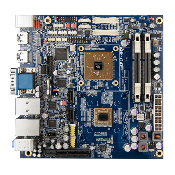
EPIA EPIA- - - - M920 M920 User Manual User Manual EPIA EPIA M920 M920 User Manual User Manual 1.3. Layout Diagram Figure Figure 1 1 1 1 : Layout diagram of EPIA : Layout diagram of EPIA- - - - M920 mainboard (top view M920 mainboard (top view) ) ) ) Figure Figure... - Page 21 EPIA EPIA- - - - M920 M920 User Manual User Manual EPIA EPIA M920 M920 User Manual User Manual Item Item Item Item Description Description Description Description PS/2 keyboard and mouse pin header (JKBMS) SMBus pin header (SMBUS1) Digital I/O pin headers (DIO1) VDD Power Select jumper (J9) COM4 pin header Front panel pin header (F_PANEL)
-
Page 22: Product Dimensions
EPIA EPIA- - - - M920 M920 User Manual User Manual EPIA EPIA M920 M920 User Manual User Manual 1.4. Product Dimensions Figure Figure Figure Figure 2 2 2 2 : Mounting holes and dimension : Mounting holes and dimension : Mounting holes and dimension : Mounting holes and dimensions of the EPIA s of the EPIA... -
Page 23: Height Distribution
EPIA EPIA- - - - M920 M920 User Manual User Manual EPIA EPIA M920 M920 User Manual User Manual 1.5. Height Distribution Figure Figure 4 4 4 4 : : : : Height distribution of the EPIA Height distribution of the EPIA- - - - M920 mainboard M920 mainboard (for fan model) (for fan model) Figure... - Page 24 EPIA EPIA- - - - M920 M920 User Manual User Manual EPIA EPIA M920 M920 User Manual User Manual Figure Figure Figure Figure 5 5 5 5 : : : : Height distribution of the EPIA Height distribution of the EPIA Height distribution of the EPIA- - - - M920 mainboard (for fanless model) Height distribution of the EPIA M920 mainboard (for fanless model)
-
Page 25: I/O Interface I/O Interface
2. 2. 2. 2. I/O Interface I/O Interface I/O Interface I/O Interface The VIA EPIA-M920 has a wide selection of interfaces integrated into the board. It includes a selection of frequently used ports as part of the external I/O coastline. 2.1. External I/O Ports... -
Page 26: Ps/2 Port
EPIA EPIA- - - - M920 M920 User Manual User Manual EPIA EPIA M920 M920 User Manual User Manual 2.1.1. PS/2 Port The mainboard has two integrated PS/2 ports for keyboard and mouse. Each port is using the 6-pin Mini-DIN connector. The color purple is used for a PS/2 keyboard while the color green is used for a PS/2 mouse. -
Page 27: Hdmi Port
EPIA EPIA- - - - M920 M920 User Manual User Manual EPIA EPIA M920 M920 User Manual User Manual ® 2.1.2. HDMI Port ® ® The integrated 19-pin HDMI port uses an HDMI Type A receptacle ® ® connector as defined in the HDMI specification. -
Page 28: Com Connector
EPIA EPIA- - - - M920 M920 User Manual User Manual EPIA EPIA M920 M920 User Manual User Manual 2.1.3. COM Connector The integrated 9-pin COM connector uses a male DE-9 connector. The COM (COM1) connector supports the RS-232 standard. The pinout of the COM connector is shown below. -
Page 29: Lan Port: Gigabit Ethernet
EPIA EPIA- - - - M920 M920 User Manual User Manual EPIA EPIA M920 M920 User Manual User Manual 2.1.4. RJ-45 LAN Port: Gigabit Ethernet The integrated 8-pin Gigabit Ethernet port is using an 8 Position 8 Contact (8P8C) receptacle connector (commonly referred to as RJ-45). The pinout of the Gigabit Ethernet port is shown below. -
Page 30: Audio Ports
EPIA EPIA- - - - M920 M920 User Manual User Manual EPIA EPIA M920 M920 User Manual User Manual 2.1.5. Audio Ports There are three audio jack receptacles integrated into a single stack on the I/O coastline. Each receptacle can fit a 3.5 mm Tip Ring Sleeve (TRS) connector to enable connections to Line-in, Line-out, and Mic-in. -
Page 31: Vga Connector
EPIA EPIA- - - - M920 M920 User Manual User Manual EPIA EPIA M920 M920 User Manual User Manual 2.1.6. VGA Connector The integrated 15-pin VGA connector uses a female DE-15 connector. The VGA connector is for connecting to analog displays. The pinout of the VGA connector is shown below. -
Page 32: Usb 2.0 Port
User Manual 2.1.7. USB 2.0 Port There are two integrated USB 2.0 ports in EPIA-M920 mainboard. The USB 2.0 interface port gives complete Plug and Play and hot swap capability for external devices and it complies with USB UHCI, rev. 2.0. Each USB port is using the USB Type A receptacle connector. -
Page 33: Usb 3.0 Port
User Manual 2.1.8. USB 3.0 Port The EPIA-M920 mainboard provides two USB 3.0 ports, also known as SuperSpeed USB. The USB 3.0 port has a maximum data transfer rate up to 5 Gbps and offers a backwards compatible with previous USB 2.0 specifications. -
Page 34: Onboard Connectors
EPIA EPIA- - - - M920 M920 User Manual User Manual EPIA EPIA M920 M920 User Manual User Manual 2.2. Onboard Connectors 2.2.1. ATX Power Connector The mainboard has a 20-pin ATX power connector onboard. The ATX power connector is labeled as “ATX_POWER1”. The pinout of the ATX power connector is shown below. -
Page 35: Lvds Panel Connectors
EPIA EPIA- - - - M920 M920 User Manual User Manual EPIA EPIA M920 M920 User Manual User Manual 2.2.2. LVDS Panel Connectors The mainboard has two LVDS panel connectors: LVDS1 and LVDS2. LVDS1 connector is controlled by VIA VX11H chipset while the LVDS2 connector is controlled by VT1636 LVDS transmitter. - Page 36 EPIA EPIA- - - - M920 M920 User Manual User Manual EPIA EPIA M920 M920 User Manual User Manual Signal Signal Signal Signal Signal Signal Signal Signal PVDD1 PVDD1 -LD1C0 +LD1C0 -LD1C1 +LD1C1 -LD1C2 + LD1C2 -LCLK1 + LCLK1 -LD1C3 + LD1C3 LVDSPCLK LPDSPD...
- Page 37 EPIA EPIA- - - - M920 M920 User Manual User Manual EPIA EPIA M920 M920 User Manual User Manual Signal Signal Signal Signal Signal Signal Signal Signal PVDD2 -A4_L PVDD2 A4_L -A5_L -A0_L A5_L A0_L -A6_L -A1_L A6_L A1_L -CLK2_L -A2_L CLK2_L A2_L...
-
Page 38: Lvds Inverter Connector
EPIA EPIA- - - - M920 M920 User Manual User Manual EPIA EPIA M920 M920 User Manual User Manual 2.2.3. LVDS Inverter Connector The mainboard has two inverters for controlling the LVDS panel backlight and brightness. INVERTER1 corresponds to the LVDS1 panel connector. INVERTER2 corresponds to the LVDS2 panel connector. - Page 39 EPIA EPIA- - - - M920 M920 User Manual User Manual EPIA EPIA M920 M920 User Manual User Manual Table Table Table Table 13 13 13 13: : : : L L L L VDS Inverter connector pinout VDS Inverter connector pinout VDS Inverter connector pinout VDS Inverter connector pinout...
-
Page 40: Digital I/O Pin Header
EPIA EPIA- - - - M920 M920 User Manual User Manual EPIA EPIA M920 M920 User Manual User Manual 2.2.4. Digital I/O Pin Header The mainboard includes one Digital I/O pin header that supports four GPO and four GPI pins. Figure Figure Figure... -
Page 41: External Thermal Resister Pin Header
EPIA EPIA- - - - M920 M920 User Manual User Manual EPIA EPIA M920 M920 User Manual User Manual 2.2.5. External Thermal Resister Pin Header The mainboard supports a pin header (3-pin) that allows the connection of a temperature sensor cable for detecting the system’s internal air temperature. The temperature reading can be seen in the BIOS Setup Utility. -
Page 42: Front Panel Pin Header
EPIA EPIA- - - - M920 M920 User Manual User Manual EPIA EPIA M920 M920 User Manual User Manual 2.2.6. Front Panel Pin Header The Front panel pin header consists of 15 pins in a 16-pin block. Pin 15 is keyed. - Page 43 EPIA EPIA- - - - M920 M920 User Manual User Manual EPIA EPIA M920 M920 User Manual User Manual SPEAK -SLEEPLED — Table Table 16 16: Front panel pin header pinout : Front panel pin header pinout Table Table 16 16 : Front panel pin header pinout : Front panel pin header pinout...
-
Page 44: Smbus Pin Header
EPIA EPIA- - - - M920 M920 User Manual User Manual EPIA EPIA M920 M920 User Manual User Manual 2.2.7. SMBus Pin Header The SMBus pin header consists of three pins that allow connecting the SMBus devices. Devices communicate with a SMBus host and/or other SMBus devices using the SMBus interface. -
Page 45: Cpu And System Fan Connectors
EPIA EPIA- - - - M920 M920 User Manual User Manual EPIA EPIA M920 M920 User Manual User Manual 2.2.8. CPU and System Fan Connectors There are two fan connectors on board: one for the CPU and one for the chassis. - Page 46 EPIA EPIA- - - - M920 M920 User Manual User Manual EPIA EPIA M920 M920 User Manual User Manual System fan (SYSFAN1) System fan (SYSFAN1) System fan (SYSFAN1) System fan (SYSFAN1) Signal Signal Signal Signal F_I02 F_PWM2 Ground Table Table 18 18: CPU and System fan connector pinouts : CPU and System fan connector pinouts Table...
-
Page 47: Sata Connectors
EPIA EPIA- - - - M920 M920 User Manual User Manual EPIA EPIA M920 M920 User Manual User Manual 2.2.9. SATA Connectors The two SATA connectors on board can support up to 3 Gb/s transfer speeds. The SATA connectors are labeled as “SATA1” and “SATA2”. The pinout of the SATA connectors are shown below. -
Page 48: Usb 2.0 Pin Headers
EPIA EPIA- - - - M920 M920 User Manual User Manual EPIA EPIA M920 M920 User Manual User Manual 2.2.10. USB 2.0 Pin Headers The mainboard has two USB 2.0 pin header blocks that support up to four USB 2.0 ports. The pin header blocks are labeled as “USB_1”and “USB_2. The pinout of the USB 2.0 pin headers are shown below. -
Page 49: Com Pin Header For Com2~Com4
EPIA EPIA- - - - M920 M920 User Manual User Manual EPIA EPIA M920 M920 User Manual User Manual 2.2.11. COM Pin Header for COM2~COM4 There are a total of three COM pin headers on the mainboard. Each COM pin header supports the RS-232 standard. -
Page 50: Ps/2 Keyboard And Mouse Pin Header
EPIA EPIA- - - - M920 M920 User Manual User Manual EPIA EPIA M920 M920 User Manual User Manual 2.2.12. PS/2 Keyboard and Mouse Pin Header The mainboard has a pin header for a PS/2 keyboard and mouse. The pin header is labeled as “JKBMS”. -
Page 51: Front Audio Pin Header
EPIA EPIA- - - - M920 M920 User Manual User Manual EPIA EPIA M920 M920 User Manual User Manual 2.2.13. Front Audio Pin Header In addition to the TRS audio jacks on the external I/O coastline, the mainboard has a pin header for Line-out and Mic-in. The pin header is labeled as “F_AUDIO1”. -
Page 52: Spi Address Select Pin Header
EPIA EPIA- - - - M920 M920 User Manual User Manual EPIA EPIA M920 M920 User Manual User Manual 2.2.14. SPI Address Select Pin Header The connector is labeled as “J6”. The pinout of the SPI address select pin header is shown below. Figure Figure Figure... -
Page 53: Spi Pin Header
EPIA EPIA- - - - M920 M920 User Manual User Manual EPIA EPIA M920 M920 User Manual User Manual 2.2.15. SPI Pin Header The mainboard has one 8-pin SPI pin header. The SPI (Serial Peripheral Interface) pin-header is used to connect to the SPI BIOS programming fixture. The pin header is labeled as “SPI1”. -
Page 54: Lpc Pin Header
EPIA EPIA- - - - M920 M920 User Manual User Manual EPIA EPIA M920 M920 User Manual User Manual 2.2.16. LPC Pin Header The mainboard has one LPC pin header for connecting LPC devices. The pin header is labeled as “LPC”. The pinout of the pin header is shown below. F F F F igure igure igure... -
Page 55: Spdif Connector
EPIA EPIA- - - - M920 M920 User Manual User Manual EPIA EPIA M920 M920 User Manual User Manual 2.2.17. SPDIF Connector The mainboard has one 3-pin SPDIF (Sony Philips Digital Interface) connector. The SPDIF output provides digital audio to external speakers or compressed AC3 data to an external Dolby Digital Decoder. -
Page 56: Cmos Battery Slot
EPIA EPIA- - - - M920 M920 User Manual User Manual EPIA EPIA M920 M920 User Manual User Manual 2.2.18. CMOS Battery Slot The mainboard is equipped with a CMOS battery slot, which is compatible with CR2032 coin batteries. The CMOS battery slot is labeled as “BAT2”. When inserting a CR2032 coin battery, be sure that the positive side is facing the locking clip. -
Page 57: Usb 3.0 Connector
EPIA EPIA- - - - M920 M920 User Manual User Manual EPIA EPIA M920 M920 User Manual User Manual 2.2.19. USB 3.0 Connector The mainboard has onboard USB connector that enables additional USB 3.0 connector. The connector is labeled as “J8”. The pinout of the USB connector is shown below. -
Page 58: Jumpers
EPIA EPIA- - - - M920 M920 User Manual User Manual EPIA EPIA M920 M920 User Manual User Manual 3. 3. 3. 3. Jumpers Jumpers Jumpers Jumpers Jumper Description Jumper Description Jumper Description Jumper Description A jumper consists of pair conductive pins used to close in or bypass an electronic circuit to set up or configure particular feature using a jumper cap. - Page 59 EPIA EPIA- - - - M920 M920 User Manual User Manual EPIA EPIA M920 M920 User Manual User Manual Caution: Caution: Caution: Caution: Make sure to install the jumper cap on the correct pins. Installing it in the wrong pin might cause damage and malfunction.
-
Page 60: Clear Cmos Jumper
EPIA EPIA- - - - M920 M920 User Manual User Manual EPIA EPIA M920 M920 User Manual User Manual 3.1. Clear CMOS Jumper The onboard CMOS RAM stores system configuration data and has an onboard battery power supply. To reset the CMOS settings, set the jumper on pins 2 and 3 while the system is off. -
Page 61: Sata Dom Power Select Jumper
EPIA EPIA- - - - M920 M920 User Manual User Manual EPIA EPIA M920 M920 User Manual User Manual 3.2. SATA DOM Power Select Jumper The SATA connectors can be used to support Disk-on-Module flash drives. The power for SATA DOM is controlled by the jumper labeled as “J12”.When the jumpers are set, +5V will be delivered to the 7 pin of the SATA connectors. -
Page 62: Com1 And Com2 Voltage Select Jumper
EPIA EPIA- - - - M920 M920 User Manual User Manual EPIA EPIA M920 M920 User Manual User Manual 3.3. COM1 and COM2 Voltage Select Jumper The voltage for COM1 and COM2 is controlled by the jumper labeled as “J11”. The voltage can be either +5V or +12V. +5V is the default setting. The odd pin numbers correspond to COM1. -
Page 63: Com3 And Com4 Voltage Select Jumper
EPIA EPIA- - - - M920 M920 User Manual User Manual EPIA EPIA M920 M920 User Manual User Manual 3.4. COM3 and COM4 Voltage Select Jumper The voltage for COM3 and COM4 is controlled by the jumper labeled as “J13”. The voltage can be either +5V or +12V. +5V is the default setting. The odd pin numbers correspond to COM3. -
Page 64: Vdd Power Select
EPIA EPIA- - - - M920 M920 User Manual User Manual EPIA EPIA M920 M920 User Manual User Manual 3.5. VDD Power Select The connector is labeled as “J9”. The pinout of the VDD power select is shown below. Figure Figure 39 39: VDD power select jumper diagram : VDD power select jumper diagram... -
Page 65: Lvds Jumper Settings
EPIA EPIA- - - - M920 M920 User Manual User Manual EPIA EPIA M920 M920 User Manual User Manual 3.6. LVDS Jumper Settings The LVDS connectors and LVDS inverters can operate on different input voltages. The mainboard has one jumper (J14) that controls the voltage delivered to the LVDS1 panel connector and input voltage delivered to the INVERTER1 connector. -
Page 66: Expansion Slots
EPIA EPIA- - - - M920 M920 User Manual User Manual EPIA EPIA M920 M920 User Manual User Manual 4. 4. 4. 4. Expansion S Expansion Slots lots Expansion S Expansion S lots lots 4.1. DDR3 Memory Slots The mainboard provides two DDR3 SODIMM memory slots. The memory slot can accommodate up to 8 GB of 1333 MHz memory per slot. -
Page 67: Installing A Memory Module
EPIA EPIA- - - - M920 M920 User Manual User Manual EPIA EPIA M920 M920 User Manual User Manual 4.1.1. Installing a Memory Module Step 1 Step 1 Step 1 Step 1 Disengage the locking clasps at both ends of the memory slot. Align the notch on the bottom of the DDR3 memory module with the notch wedge in the slot. -
Page 68: Removing A Memory Module
EPIA EPIA- - - - M920 M920 User Manual User Manual EPIA EPIA M920 M920 User Manual User Manual 4.1.2. Removing a Memory Module Step 1 Step 1 Step 1 Step 1 Disengage the locking clasps at both ends of the memory slot. Figure Figure Figure... -
Page 69: Pci Express Slot
EPIA EPIA- - - - M920 M920 User Manual User Manual EPIA EPIA M920 M920 User Manual User Manual 4.1.3. PCI Express Slot The PCI Express slot provides support for 4-lane cards. Due to the orientation of the slot, a riser card module must be used. -
Page 70: Hardware Installation Hardware Installation
Hardware Installation 5.1. Installing into a Chassis The EPIA-M920 can be fitted into any chassis that has the mounting holes for compatible with the standard Mini-ITX mounting hole locations. Additionally, the chassis must meet the minimum height requirements for specified areas of the mainboard. -
Page 71: Suggested Minimum Chassis Height
EPIA EPIA- - - - M920 M920 User Manual User Manual EPIA EPIA M920 M920 User Manual User Manual Each side of the mainboard should have a buffer zone from the internal wall of the chassis. The side of the mainboard that accommodates the I/O coastline should have a buffer of 1.00 mm. - Page 72 EPIA EPIA- - - - M920 M920 User Manual User Manual EPIA EPIA M920 M920 User Manual User Manual Figure Figure Figure Figure 49 49 49 49: Suggested minimum internal chassis ceiling height (for fan model) : Suggested minimum internal chassis ceiling height (for fan model) : Suggested minimum internal chassis ceiling height (for fan model) : Suggested minimum internal chassis ceiling height (for fan model)
-
Page 73: Suggested Keepout Areas
EPIA EPIA- - - - M920 M920 User Manual User Manual EPIA EPIA M920 M920 User Manual User Manual 5.1.3. Suggested keepout areas The figure below shows the areas of the mainboard that is highly suggested to leave unobstructed. Figure Figure Figure Figure 50... -
Page 74: Bios Setup Utility Bios Setup Utility
EPIA EPIA- - - - M920 M920 User Manual User Manual EPIA EPIA M920 M920 User Manual User Manual 6. 6. 6. 6. BIOS Setup Utility BIOS Setup Utility BIOS Setup Utility BIOS Setup Utility 6.1. Entering the BIOS Setup Utility Power on the computer and press Delete Delete Delete during the beginning of the boot... -
Page 75: Navigating The Bios Menus
EPIA EPIA- - - - M920 M920 User Manual User Manual EPIA EPIA M920 M920 User Manual User Manual 6.3. Navigating the BIOS Menus Left>/<Right Right> The main menu displays all the BIOS setup categories. Use the <Left Left Left Right Right and <Up... -
Page 76: Main Menu
EPIA EPIA- - - - M920 M920 User Manual User Manual EPIA EPIA M920 M920 User Manual User Manual 6.5. Main Menu The System Overview screen is the default screen that is shown when the BIOS Setup Utility is launched. This screen can be accessed by traversing the navigation bar to the “Main”... -
Page 77: System Date
EPIA EPIA- - - - M920 M920 User Manual User Manual EPIA EPIA M920 M920 User Manual User Manual 6.5.4. System Date This section shows the current system date. Press Tab Tab to traverse right and Shift+Tab Shift+Tab to traverse left through the month, day, and year segments. The + + + + Shift+Tab Shift+Tab and - - - - keys on the number pad can be used to change the values. -
Page 78: Advanced Settings
EPIA EPIA- - - - M920 M920 User Manual User Manual EPIA EPIA M920 M920 User Manual User Manual 6.6. Advanced Settings The Advanced Settings screen shows a list of categories that can provide access to a sub-screen. Sub-screen links can be identified by the preceding right-facing arrowhead. -
Page 79: Acpi Settings
EPIA EPIA- - - - M920 M920 User Manual User Manual EPIA EPIA M920 M920 User Manual User Manual 6.6.1. ACPI Settings ACPI grants the operating system direct control over system power management. The ACPI Configuration screen can be used to set a number of power management related functions. -
Page 80: S5 Rtc Wake Settings
EPIA EPIA- - - - M920 M920 User Manual User Manual EPIA EPIA M920 M920 User Manual User Manual 6.6.2. S5 RTC Wake Settings Enable system to wake from S5 using RTC alarm. Figure Figure 54 54: Illustration of S5 RTC Wake Settings screen : Illustration of S5 RTC Wake Settings screen Figure Figure... -
Page 81: Cpu Information
EPIA EPIA- - - - M920 M920 User Manual User Manual EPIA EPIA M920 M920 User Manual User Manual 6.6.3. CPU Information The CPU Information screen shows detailed information about the built-in processor. Figure Figure Figure Figure 55 55 55 55: Illustration of CPU Information screen : Illustration of CPU Information screen : Illustration of CPU Information screen... -
Page 82: Sata Configuration
EPIA EPIA- - - - M920 M920 User Manual User Manual EPIA EPIA M920 M920 User Manual User Manual 6.6.4. SATA Configuration The SATA Configuration screen allows the user to view and configure the settings of the SATA configuration settings. Figure Figure Figure... -
Page 83: F71869 Super Io Configuration
EPIA EPIA- - - - M920 M920 User Manual User Manual EPIA EPIA M920 M920 User Manual User Manual 6.6.5. F71869 Super IO Configuration The F71869 Super IO Configuration screen allows the user to set system Super IO Chip parameters. Figure Figure Figure... -
Page 84: F71869 H/W Monitor
EPIA EPIA- - - - M920 M920 User Manual User Manual EPIA EPIA M920 M920 User Manual User Manual 6.6.6. F71869 H/W Monitor F71869 H/W Monitor shows Monitor hardware status. Figu Figu Figu Figure re re re 58 58 58 58: Illustration of F71869 H/W Monitor screen : Illustration of F71869 H/W Monitor screen : Illustration of F71869 H/W Monitor screen... -
Page 85: Clock Generator Configuration
EPIA EPIA- - - - M920 M920 User Manual User Manual EPIA EPIA M920 M920 User Manual User Manual 6.6.7. Clock Generator Configuration The Clock Generator Configuration screen enables access to the Spread Spectrum Setting feature. Figure Figure Figure Figure 59 59 59 59: Illustration of Clock Generator Configuration screen : Illustration of Clock Generator Configuration screen... -
Page 86: On Board Configuration
EPIA EPIA- - - - M920 M920 User Manual User Manual EPIA EPIA M920 M920 User Manual User Manual 6.6.8. On Board Configuration The OnBoard Device Configuration screen has the following features. Figure Figure Figure Figure 60 60 60 60: Illustration of On Board Configuration screen : Illustration of On Board Configuration screen : Illustration of On Board Configuration screen : Illustration of On Board Configuration screen... - Page 87 EPIA EPIA- - - - M920 M920 User Manual User Manual EPIA EPIA M920 M920 User Manual User Manual 6.6.8.4. 6.6.8.4. 1CH LVDS Backlight Control 1CH LVDS Backlight Control 6.6.8.4. 6.6.8.4. 1CH LVDS Backlight Control 1CH LVDS Backlight Control Backlight Control Backlight Control Backlight Control Backlight Control...
-
Page 88: Chipset Settings
EPIA EPIA- - - - M920 M920 User Manual User Manual EPIA EPIA M920 M920 User Manual User Manual 6.7. Chipset Settings The Chipset Settings screen shows a list of categories that can provide access to a sub-screen. Sub-screen links can be identified by the preceding right- facing arrowhead. -
Page 89: Dram Configuration
EPIA EPIA- - - - M920 M920 User Manual User Manual EPIA EPIA M920 M920 User Manual User Manual 6.7.1. DRAM Configuration The DRAM Configuration screen has two features for controlling the system DRAM. All other DRAM features are automated and cannot be accessed. Figure Figure Figure... - Page 90 EPIA EPIA- - - - M920 M920 User Manual User Manual EPIA EPIA M920 M920 User Manual User Manual 533 MHz 533 MHz 533 MHz 533 MHz The 533 MHz option forces the BIOS to be fixed at 1066 MHz for DDR3 memory modules.
- Page 91 EPIA EPIA- - - - M920 M920 User Manual User Manual EPIA EPIA M920 M920 User Manual User Manual 6.7.1.2. 6.7.1.2. 6.7.1.2. 6.7.1.2. VGA Share Memory (Frame Buffer) VGA Share Memory (Frame Buffer) VGA Share Memory (Frame Buffer) VGA Share Memory (Frame Buffer) The VGA Share Memory feature enables the user to choose the amount of the system memory to reserve for use by the integrated graphics controller.
-
Page 92: Video Configuration
EPIA EPIA- - - - M920 M920 User Manual User Manual EPIA EPIA M920 M920 User Manual User Manual 6.7.2. Video Configuration The Video Configuration screen has features for controlling the integrated graphics controller in the VX11H chipset. Figure Figure Figure Figure 63 63 63... -
Page 93: Panel Type
EPIA EPIA- - - - M920 M920 User Manual User Manual EPIA EPIA M920 M920 User Manual User Manual 6.7.2.4. 6.7.2.4. 6.7.2.4. 6.7.2.4. Select Display Device 1 and 2 Select Display Device 1 and 2 Select Display Device 1 and 2 Select Display Device 1 and 2 The Select Display Device feature enables the user to choose a specific display interface. -
Page 94: Uart Configuration
EPIA EPIA- - - - M920 M920 User Manual User Manual EPIA EPIA M920 M920 User Manual User Manual 6.7.3. UART Configuration The UART Configuration screen allows the user to set UART configuration parameters. Figure Figure Figure Figure 64 64 64 64: Illustration of UART Configuration screen : Illustration of UART Configuration screen : Illustration of UART Configuration screen... -
Page 95: Pmu_Acpi Configuration
EPIA EPIA- - - - M920 M920 User Manual User Manual EPIA EPIA M920 M920 User Manual User Manual 6.7.4. PMU_ACPI Configuration The PMU_ACPI Configuration screen can be used to set a number of power management related functions. Figure Figure 65 65: Illustration of PMU_ACPI Configuration screenOther Control : Illustration of PMU_ACPI Configuration screenOther Control Figure... - Page 96 EPIA EPIA- - - - M920 M920 User Manual User Manual EPIA EPIA M920 M920 User Manual User Manual 6.7.4.1.1. 6.7.4.1.1. AC Loss Auto AC Loss Auto- - - - rest restart 6.7.4.1.1. 6.7.4.1.1. AC Loss Auto AC Loss Auto rest rest AC Loss Auto-restart defines how the system will respond after AC power has...
-
Page 97: Hdac Configuration
EPIA EPIA- - - - M920 M920 User Manual User Manual EPIA EPIA M920 M920 User Manual User Manual 6.7.5. HDAC Configuration HDAC Configuration Parameters. Figure Figure Figure Figure 67 67 67 67: Illustration of HDAC Configuration screen : Illustration of HDAC Configuration screen : Illustration of HDAC Configuration screen : Illustration of HDAC Configuration screen 6.7.5.1. -
Page 98: Sdio_Cr Configuration
EPIA EPIA- - - - M920 M920 User Manual User Manual EPIA EPIA M920 M920 User Manual User Manual 6.7.6. SDIO_CR Configuration The SDIO_CR Configuration screen can be used to set SDIO_CR configuration parameters. Figure Figure Figure Figure 68 68 68 68: Illustration of S : Illustration of S : Illustration of S... - Page 99 EPIA EPIA- - - - M920 M920 User Manual User Manual EPIA EPIA M920 M920 User Manual User Manual This feature has 2 options: Enable or Disable SDR50 Support. 6.7.6.1.7. 6.7.6.1.7. SDR104 Sup SDR104 Support port 6.7.6.1.7. 6.7.6.1.7. SDR104 Sup SDR104 Sup port port...
-
Page 100: Others Configuration
EPIA EPIA- - - - M920 M920 User Manual User Manual EPIA EPIA M920 M920 User Manual User Manual 6.7.7. Others Configuration The Others Configuration screen can be used to set Watchdog Timer Configuration and Keyboard/Mouse Wakeup Configuration. Figure Figure Figure Figure 69 69 69... -
Page 101: Boot Settings
EPIA EPIA- - - - M920 M920 User Manual User Manual EPIA EPIA M920 M920 User Manual User Manual 6.8. Boot Settings The Boot Settings screen has a single link that goes to the Boot Configuration, Boot Configuration, Boot Configuration, Boot Configuration, and Boot Option Priority Boot Option Priority screens. -
Page 102: Boot Option Priorities
EPIA EPIA- - - - M920 M920 User Manual User Manual EPIA EPIA M920 M920 User Manual User Manual 6.8.2. Boot Option Priorities The Boot Option Priorities screen lists all bootable devices. 6.8.2.1. 6.8.2.1. Boot Option #1 Boot Option #1 6.8.2.1. -
Page 103: Security Settings
EPIA EPIA- - - - M920 M920 User Manual User Manual EPIA EPIA M920 M920 User Manual User Manual 6.9. Security Settings The Security Settings screen provides a way to restrict access to the BIOS or even the entire system. Figure Figure 71 71: Illustration of Security Settings screen... -
Page 104: Password Check
EPIA EPIA- - - - M920 M920 User Manual User Manual EPIA EPIA M920 M920 User Manual User Manual 6.9.1.2. 6.9.1.2. Password Check Password Check 6.9.1.2. 6.9.1.2. Password Check Password Check This feature is compulsory when the Change Supervisor Password Change Supervisor Password option is set. -
Page 105: Save & Exit Options
EPIA EPIA- - - - M920 M920 User Manual User Manual EPIA EPIA M920 M920 User Manual User Manual 6.10. Save & Exit Options The Save & Exit Configuration screen has the following features: Figure Figure Figure Figure 72 72 72 72: Illustration of Save : Illustration of Save : Illustration of Save... -
Page 106: Discard Changes And Reset
EPIA EPIA- - - - M920 M920 User Manual User Manual EPIA EPIA M920 M920 User Manual User Manual 6.10.4. Discard Changes and Reset This command reverts all changes to the settings that were in place when the BIOS Setup Utility was launched. The “F7” hotkey can also be used to trigger this command. -
Page 107: Driver Installation Driver Installation
Driver Installation Driver Installation 7.1. Microsoft Driver Support The VIA EPIA-M920 mainboard is compatible with Microsoft operating systems. The latest Windows drivers can be downloaded from the VIA Embedded website at www.viaembedded.com. For embedded operating systems, the related drivers can be found in the VIA Embedded website at www.viaembedded.com. -
Page 108: Appendix A. Power Consumption Report
Power Consumption Report Power Consumption Report Power Consumption Report Power consumption tests were performed on the VIA EPIA-M920. The following tables represent the breakdown of the voltage, amp and wattage values while running common system applications. A.1. EPIA-M920 Rev. 2 DVT... -
Page 109: Playing Mp3-Media Player
EPIA EPIA- - - - M920 M920 User Manual User Manual EPIA EPIA M920 M920 User Manual User Manual A.1.2. Playing MP3-Media Player Measured Voltage Measured Voltage Measured Amp. Measured Amp. Watts Watts Measured Voltage Measured Voltage Measured Amp. Measured Amp. Watts Watts Main Board +3.3V... -
Page 110: Run Burn-In Test
EPIA EPIA- - - - M920 M920 User Manual User Manual EPIA EPIA M920 M920 User Manual User Manual Main Board 5VSB 4.783 0.865 4.137 Main Board +12V 11.618 0.450 5.228 Main Board Power Consumption 13.342 MEAN MEAN MEAN MEAN Measured Voltage Measured Voltage Measured Voltage... -
Page 111: Eup/Erp Enable S3
EPIA EPIA- - - - M920 M920 User Manual User Manual EPIA EPIA M920 M920 User Manual User Manual MEAN MEAN Measured Voltage Measured Voltage Measured Amp. Measured Amp. Watts Watts MEAN MEAN Measured Voltage Measured Voltage Measured Amp. Measured Amp. Watts Watts Main Board +3.3V... -
Page 112: Eup/Erp Enable S5
EPIA EPIA- - - - M920 M920 User Manual User Manual EPIA EPIA M920 M920 User Manual User Manual A.1.9. EuP/ErP Enable S5 Measured Voltage Measured Voltage Measured Amp. Measured Amp. Watts Watts Measured Voltage Measured Voltage Measured Amp. Measured Amp. Watts Watts Main Board +3.3V...
Need help?
Do you have a question about the EPIA-M920 and is the answer not in the manual?
Questions and answers