Table of Contents
Advertisement
USER MANUAL
I
A
C
NDUSTRIAL
IR
OMPRESSOR
TSR32
V
S
D
& F
S
D
ARIABLE
PEED
RIVE
IXED
PEED
RIVE
PART NUMBER:
02250178-398 R00
KEEP FOR
FUTURE
WARRANTY NOTICE
REFERENCE
SULLAIR CORPORATION
©
Failure to follow the instructions
The information in this manual is current
and procedures in this manual or,
as of its publication date, and applies to
misuse of this equipment will
compressor serial number:
VOID its warranty!
200809300000
and all subsequent serial numbers.
Advertisement
Table of Contents

Related Manuals for Sullair TSR32


Summary of Contents for Sullair TSR32
- Page 1 USER MANUAL NDUSTRIAL OMPRESSOR TSR32 & F ARIABLE PEED RIVE IXED PEED RIVE PART NUMBER: 02250178-398 R00 KEEP FOR FUTURE WARRANTY NOTICE REFERENCE SULLAIR CORPORATION © Failure to follow the instructions The information in this manual is current and procedures in this manual or,...
- Page 2 AIR CARE SEMINAR TRAINING Sullair Air Care Seminars are courses that provide hands-on instruction for the proper operation, maintenance, and servicing of Sullair products. Individual seminars on Industrial compressors and compressor electrical systems are offered at regular intervals throu ate headquarters training facility located at Michigan City, Indiana.
-
Page 3: Table Of Contents
TABLE OF CONTENTS GENERAL PERSONAL PROTECTIVE EQUIPMENT PRESSURE RELEASE FIRE AND EXPLOSION MOVING PARTS HOT SURFACES, SHARP EDGES AND SHARP CORNERS TOXIC AND IRRITATING SUBSTANCES ELECTRICAL SHOCK LIFTING 1.10 ENTRAPMENT INTRODUCTION COMPRESSOR COMPONENT DESCRIPTION COMPRESSOR COOLING AND AL DESCRIPTION COMPRESSOR DISCHARGE SYST VSD CONTROL SYSTEM FIXED SPEED CONTROL SYSTEM, FUNCTIONAL DESCRIPTION FUNCTIONAL DESCRIPTION... - Page 4 TABLE OF CONTENTS VENTILATION AND COOLING SERVICE AIR PIPING AUXILIARY RECEIVER TANK COUPLING ALIGNMENT CHECK FLUID LEVEL CHECK ELECTRICAL PREPARATION MOTOR ROTATION DIRECTION CHECK ROUTINE OPERATION SETUP GENERAL MAINTENANCE AFTER INITIAL 50 HOURS OF OPERATION MAINTENANCE EVERY 2000 HOURS FLUID MAINTENANCE FILTER MAINTENANCE AIR FILTER MAINTENANCE SEPARATOR MAINTENANCE...
-
Page 5: General
GENERAL tions relative to personal protective equipment, such as eye and face protective equipment, Sullair Corporation and its subsidiaries design and respiratory protective equipment, equipment manufacture all of their products so they can be intended to protect the extremities, protective operated safely. -
Page 6: 1.4 Fire And Explosion
SECTION 1 inside diameter to reduce pressure in case of accumulate on, under or around acoustical mate- hose failure. rial, or on any external surfaces of the air com- pressor. Wipe down using an aqueous industrial D. Flow-limiting valves are listed by pipe size and cleaner or steam clean as required. -
Page 7: 1.7 Toxic And Irritating Substances
SECTION 1 C. Wear snug-fitting clothing and confine long hair when working around this compressor, especially DANGER when exposed to hot or moving parts. D. Keep access doors, if any, closed except when making repairs or adjustments. E. Make sure all personnel are out of and/or clear of the compressor prior to attempting to start or operate it. -
Page 8: 1.8 Electrical Shock
SECTION 1 swallowed, induce vomiting by administering a tablespoon of salt, in each glass of clean, warm water until vomit is clear, then administer two DANGER teaspoons of baking soda in a glass of clean water. Have patient lay down and cover eyes to exclude light. -
Page 9: 1.10 Entrapment
SECTION 1 Keep lift operator in constant attendance when- N. Make sure pallet-mounted compressors are ever compressor is suspended. firmly bolted or otherwise secured to the pallet prior to attempting to forklift or transport them. J. Set compressor down only on a level surface NEVER attempt to forklift a compressor that is capable of safely supporting at least its weight not secured to its pallet, as uneven floors or sud-... - Page 10 NOTES...
-
Page 11: Introduction
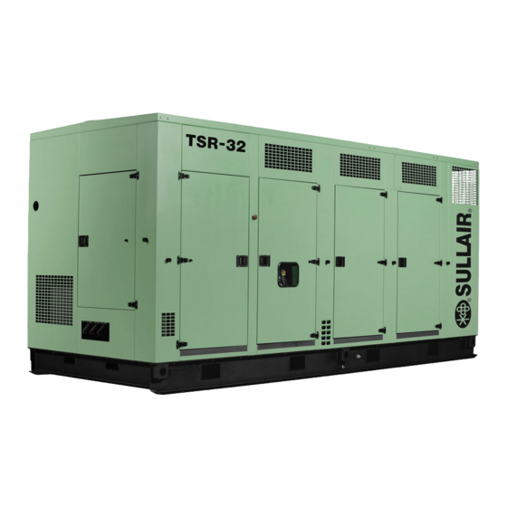
This hot air is then vented out thru enclosure exhaust duct work. The TSR32 comes equipped with a fluid filter, air/oil separator(s), control valves, and an inlet air filter. Fluid is injected into the compressor, and mixes directly with the air as the rotors turn which compresses the air. - Page 12 TSR32 USER MANUAL R00 SECTION 2 Figure 2-1: Sullair TSR-32 Rotary Screw Air Compressor- Air-Cooled VSD...
- Page 13 SECTION 2 TSR32 USER MANUAL R00 Figure 2-2: Sullair TSR-32 Rotary Screw Air Compressor- Air-Cooled Fixed Speed...
- Page 14 TSR32 USER MANUAL R00 SECTION 2 Figure 2-3: Cooling/Lubrication and Discharge System AA: FROM UNIT DISCHARGE FLANGE 1. FLUID FILTER BB: TO FLUID COOLER 2. FLUID STOP VALVE CC:FROM FLUID COOLER 3. MINIMUM PRESSURE/CHECK VALVE DD:TO UNIT INJECTION BLOCK 4. THERMAL VALVE EE: TO AFTERCOOLER 5.
-
Page 15: Compressor Cooling And
SECTION 2 TSR32 USER MANUAL R00 COMPRESSOR COOLING bottom of the separators dry side to a medium AND LUBRICATION pressure region in the compressor. Scavanged fluid is returned by a pressure differential between the DESCRIPTION receiver and compressor. Visual sight glasses are located on the return line to Refer to Figure 2-3. - Page 16 TSR32 USER MANUAL R00 SECTION 2 System consist of variable speed drive and spiral spiral valve shaft assembly, resulting in a rotary valve. The functional description of the control motion and full opening of the spiral valve, effec- system is described below in five distinct phases of tively reducing the rotor length by 50%.
- Page 17 SECTION 2 TSR32 USER MANUAL R00...
-
Page 18: Fixed Speed Control System, Functional Description
TSR32 USER MANUAL R00 SECTION 2 FIXED SPEED CONTROL psig (6.9 bar). As a result, the differential pressure SYSTEM, FUNCTIONAL regulator for the spiral valve gradually opens, apply- DESCRIPTION ing air pressure to the spiral valve actuator. Air pressure at the actuator expands the diaphragm. The Refer to Figure 2-7. -
Page 19: Functional Description
NOTES blowdown valve closes, and the inlet butterfly valve rol system, indicates the opens. Also the air pressure at the spiral valve actuator diaphragm is reduced through a vent hole at splayed, maintenance is the spiral valve differential pressure regulator, and a required. - Page 20 TSR32 USER MANUAL R00 SECTION 2...
- Page 21 SECTION 2 TSR32 USER MANUAL R00...
- Page 22 TSR32 USER MANUAL R00 SECTION 2...
- Page 23 SECTION 2 TSR32 USER MANUAL R00...
- Page 24 NOTES...
-
Page 25: Compressor Specifications
TSR32 USER MANUAL R00 Section 3 SPECIFICATIONS TABLE OF SPEC TSR-20 MOTOR TEFC HZ/VOLTAGE 460/60 DRIVE AMP 385A RATING WEIGHT (lbs) 19,900 LENGTH (in) WIDTH (in) HEIGHT (in) COMPRESSOR SPECIFICATIONS COMPRESSOR: TSR-32 Type: Rotary Screw 100 psig (7 bar) 125 psig (9 bar) / 150 psig (10.0 bar) Standard Operating Pressure: 175 psig (12.0 bar) -
Page 26: Lubrication Guide
Figure 3-1: Fluid Fill Location APPLICATION GUIDE 1. Fluid Fill Port 4. Air/Oil Separator Tank Sullair encourages its customers to participate in a 2. Fluid Level Sight Glass 5. Relief Valve fluid analysis program with the fluid suppliers. In 3. Fluid Drain Valve some cases the analysis results suggest a fluid change interval which differs from the User Manual. - Page 27 NOTES...
- Page 28 TSR32 USER MANUAL R00 SECTION 3...
- Page 29 SECTION 3 TSR32 USER MANUAL R00...
- Page 30 TSR32 USER MANUAL R00 SECTION 3...
- Page 31 SECTION 3 TSR32 USER MANUAL R00...
- Page 32 NOTES...
-
Page 33: Support And Location
TSR32 USER MANUAL R00 Section 4 INSTALLATION SUPPORT AND LOCATION pressor, free from exhaust and paint fumes, dust, metal particles, or caustic The compressor must have a stable firm foundation, chemical vapors. or mounting structure that is rigid enough to keep the... -
Page 34: Auxiliary Receiver Tank
TSR32 USER MANUAL R00 SECTION 4 IZING Pipes should be sized as a minimum to match the NOTE connection. All piping and fittings should be rated for the discharge pressure. Compressors not equipped with an auxiliary receiver tank may need to have their AUXILIARY RECEIVER TANK response times adjusted. -
Page 35: Electrical Preparation
SECTION 4 TSR32 USER MANUAL R00 ELECTRICAL PREPARATION Parallel feeder cable connections to incoming terminal cam-locks L1-L2-L3 should be tight and Interior electrical wiring is installed at the factory. clean. These are located on end of package. Behind Required customer wiring should be done by a... -
Page 36: Motor Rotation Direction Check
TSR32 USER MANUAL R00 SECTION 4 MOTOR ROTATION the motor end opposite the compressor unit, the DIRECTION CHECK shaft should turn clockwise. If reverse rotation occurs, disconnect the power to the starter and Motor rotation check must be done at compressor exchange any two of the three power input leads, start-up after the wiring has been installed. -
Page 37: Routine Operation
TSR32 USER MANUAL R00 Section 5 OPERATION ROUTINE OPERATION Before starting the compressor, check the fluid level in the receiver tank. If the fluid level is not showing in WARNING the sight glass, add the required amount of fluid up to the mid-point to bring it to its proper level. - Page 38 TSR32 USER MANUAL R00 SECTION 5 MACHINE MODEL The TSR32 VSD design can be setup in a variety of SELECTION & SUPERVISOR horsepowers and pressures. This can be done under the Factory Setup menu on the Supervisor following values reflect machine configuration.
-
Page 39: General
TSR32 USER MANUAL R00 Section 6 MAINTENANCE GENERAL This compressor requires a minimal amount of inspections maintenance. Supervisor situations requiring maintenance, or fault conditions. MAINTENANCE AFTER INITIAL 50 HOURS OF OPERATION After the initial 50 hours of operation, a few maintenance actions are required to clean the system of any foreign materials. -
Page 40: Air Filter Maintenance
TSR32 USER MANUAL R00 SECTION 6 SEPARATOR MAINTENANCE 5. Install the element into the filter canister. 6. Thread the canister and element back on the Replace the separator elements when shown by the filter head. 7. Restart compressor and check for leaks. - Page 41 SECTION 6 TSR32 USER MANUAL R00 10. Re-connect all piping making sure return line bottom of the separator element. This will CAUTION assure proper fluid return flow to the com- pressor. 11. Check the return line strainer before re-start- Relieve all pressure from the receiver tank ing the compressor.
- Page 42 TSR32 USER MANUAL R00 SECTION 6 Figure 6-4: Fluid Return / Sight Glass 1. Tube Connectors 2. Filter Assembly (I) Figure 6-5: Pressure Regulator Adjustment 3. Sight Glass/Orifice Block 1. Adjustment Nut 2. Adjustment Screw 4. Secondary Element orifice .03 (I) Rebuild Kit P/N 02250152-207 5.
- Page 43 SECTION 6 TSR32 USER MANUAL R00 ONTROL ILTER 5. Install the new element by wrapping it The regulators and solenoid valves, which control the around the jaws, engaging the cogs on the compressor, are protected by a control line filter.
- Page 44 TSR32 USER MANUAL R00 SECTION 6 Table 6-1: Troubleshooting Guide SYMPTOM PROBABLE CAUSE REMEDY Compressor Shuts Down With Loss of control voltage Check incoming power Air Demand Present Low incoming voltage Check control fuses and wiring. Consult power will provide indication of most maintenance problems if control power has not been lost.
- Page 45 SECTION 6 TSR32 USER MANUAL R00 Table 6-1: Troubleshooting Guide SYMPTOM PROBABLE CAUSE REMEDY Compressor Shuts Down With P1 is less than 10 psig (0.7 bar) First, check starter wiring. If discharge Air Demand Present (continued) (P1 low display) pressure is above 10 psig (0.7 bar) was connections from transducer.
- Page 46 NOTES...
- Page 47 NOTES...
- Page 48 Zone Des Granges BP 82 Chiwan, Shekou Michigan City, Indiana, 46360 U.S.A. 42602 Montbrison, France Shenzen, Guangdong PRV. www.sullair.com Telephone: 33-477968470 PRC POST CODE 518068 Telephone: 1-800-SULLAIR (U.S.A. only) Fax: 33-477968499 Telephone: 755-6851686 Fax: 219-874-1273 www.sullaireurope.com Fax: 755-6853473 CUSTOMER CARE www.sullair-asia.com...
Need help?
Do you have a question about the TSR32 and is the answer not in the manual?
Questions and answers
how many total package amps does the unit TSR-32 draw
The total package amps drawn by the Sullair TSR32 unit is not provided in the given context.
This answer is automatically generated