Sullair 300HH User Manual
Portable air compressors
Hide thumbs
Also See for 300HH:
- Operators manual and parts lists (164 pages) ,
- Operator's manual and parts list (120 pages) ,
- User manual (80 pages)
Table of Contents
Advertisement
USER MANUAL
P
A
C
ORTABLE
IR
OMPRESSOR
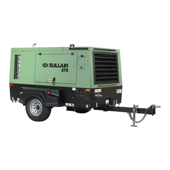
300HH, 375, 375H, 375HH, 425
425H
AND
C
S
A
F
ATERPILLAR
TANDARD AND
FTERCOOLED AND
ILTERED
PART NUMBER:
02250202-729 R01
KEEP FOR
FUTURE
WARRANTY NOTICE
REFERENCE
COPYRIGHT 2014 SULLAIR
©
Failure to follow the instructions
The information in this manual is current
and procedures in this manual or,
as of its publication date, and applies to
misuse of this equipment will
compressor serial number:
VOID its warranty!
201301260000
and all subsequent serial numbers.
Advertisement
Table of Contents

Related Manuals for Sullair 300HH


Summary of Contents for Sullair 300HH
- Page 1 USER MANUAL ORTABLE OMPRESSOR 300HH, 375, 375H, 375HH, 425 425H ATERPILLAR TANDARD AND FTERCOOLED AND ILTERED PART NUMBER: 02250202-729 R01 KEEP FOR FUTURE WARRANTY NOTICE REFERENCE COPYRIGHT 2014 SULLAIR © Failure to follow the instructions The information in this manual is current...
- Page 2 AIR CARE SEMINAR TRAINING Sullair Air Care Seminars are courses that provide hands-on instruction for the proper operation, maintenance, and servicing of Sullair products. Individual seminars on portable compressors and compressor electrical systems are offered at regular intervals throughout the year at Sullair’s corporate headquarters training facility located at Michigan City, Indiana.
- Page 3 CALIFORNIA PROPOSITION 65 1.14 SYMBOLS AND REFERENCES SECTION 2—DESCRIPTION INTRODUCTION DESCRIPTION OF COMPONENTS SULLAIR COMPRESSOR UNIT, FUNCTIONAL DESCRIPTION COMPRESSOR COOLING AND LUBRICATION SYSTEM, FUNCTION- AL DESCRIPTION COMPRESSOR DISCHARGE SYSTEM, FUNCTIONAL DESCRIPTION CAPACITY CONTROL SYSTEM, FUNCTIONAL DESCRIPTION SHUTDOWN AIR INLET SYSTEM, FUNCTIONAL DESCRIPTION INSTRUMENT PANEL GROUP, FUNCTIONAL DESCRIPTION 2.10...
-
Page 4: Table Of Contents
TABLE OF CONTENTS 2.14 ID, 375C IT4 DLQ SECTION 3—SPECIFICATIONS SPECIFICATIONS—300HH, 375, 375H CATERPILLAR SPECIFICATIONS—375HH, 425 AND 425H CATERPILLAR LUBRICATION GUIDE— COMPRESSOR APPLICATION GUIDE LUBRICATION GUIDE— ENGINE SECTION 4—OPERATIONS GENERAL PURPOSE OF CONTROLS INITIAL STARTUP/SHUTDOWN PROCEDURE RESTART PROCEDURE SECTION 5—MAINTENANCE... - Page 5 ENTIRE INSTRUCTION MANUAL. TOWING GENERAL REPARING TO Sullair designs and manufactures all of its products so they can be operated safely. However, the responsibility for safe operation rests with those who WARNING use and maintain these products. The following...
- Page 6 SECTION 1 engage coupling device or otherwise couple the compressor to the towing vehicle. CAUTION WARNING Retract the front screw jack only after attaching the compressor to the tow vehi- This equipment may be tongue heavy. DO cle. Raise the screw jack to its full up posi- NOT attempt to raise or lower the drawbar tion and pull the pin connecting the jack to by hand if the weight is more than you can...
- Page 7 SECTION 1 L. Make sure all access doors and tool box covers E. Avoid potholes, rocks and other obstructions, are closed and latched. If the compressor is and soft shoulders or unstable terrain. large enough to hold a man, make sure all per- F.
- Page 8 SECTION 1 chain fall if you cannot lift or raise the drawbar without avoiding injury to yourself or others. WARNING K. Move the towing vehicle well clear of the parked compressor and erect hazard indicators, barri- cades and/or flares (if at night) if compressor is This equipment may be tongue heavy.
- Page 9 SECTION 1 FIRE AND EXPLOSION H. Open fluid filler cap only when compressor is not running and is not pressurized. Shut down the compressor and bleed the sump (receiver) to zero internal pressure before removing the cap. WARNING Vent all internal pressure prior to opening any line, fitting, hose, valve, drain plug, connection or Do not attempt to operate the compressor other component, such as filters and line oilers,...
- Page 10 SECTION 1 H. Keep grounded and/or conductive objects such temperatures above 150 °F (66 °C). Vapors from as tools away from exposed live electrical parts the antifreeze compound are heavier than air. DO NOT store compound or discharge treated such as terminals to avoid arcing which might serve as a source of ignition.
- Page 11 SECTION 1 the engine shut off. When necessary, make adjustment, other than setting control regulator and engine RPM, with the engine shut off. If nec- T4 - WARNING essary, start the engine and check adjustment. If adjustment is incorrect, shut engine off, readjust, then restart the engine to recheck adjustment.
- Page 12 SECTION 1 should be washed with large quantities of clean DANGER water for fifteen minutes. A physician, preferably an eye specialist, should be contacted immedi- ately. INHALATION HAZARD! K. DO NOT store ether cylinders or air line anti-icer Death or serious injury can result from system antifreeze compound in operator’s cabs inhaling compressed air without using or in other similar confined areas.
- Page 13 SECTION 1 ELECTRICAL SHOCK Keep lift operator in constant attendance when- ever compressor is suspended. A. Keep the towing vehicle or equipment carrier, J. Set compressor down only on a level surface capa- compressor hoses, tools and all personnel at ble of supporting at least its net weight plus an least 10 feet (3 m) from power lines and buried additional 10% allowance for the weight of water,...
- Page 14 SECTION 1 G. Cover open cells of all compressor batteries with tery in the starting vehicle. When jump starting clean dampened cloths before attempting to 24V compressors and if the starting vehicle is provided with two (2) 12V batteries connected in jump start.
- Page 15 SECTION 1 and actions and shall be initiated only by Autho- 1. The lock shall removed “Authorized” person who put the lock on the rized Persons and done in the following sequence: energy-isolating device. No one other than 1. Review the equipment or machine to be the person/persons placing padlocks and locked and tagged out.
- Page 16 SECTION 1 1.14 SYMBOLS AND REFERENCES The symbols below may or may not be used. Please refer to the decals set forth on the machine for applicable symbols. DIESEL FUEL HEARING PROTECTION ROTARY COMPRESSOR HARD HAT TEST RUN DRAIN SAFETY GLASSES HIGH PRESSURE HEARING PROTECTION SHUT-OFF VALVE...
- Page 17 SECTION 1 ENGINE START DANGEROUS OUTLET ENGINE ECM REMOTELY CONTROLLED READ/WRITE DATA CORROSIVE INTAKE AIR EXHAUST GAS WARNING FAN GUARD DO NOT MAINTENANCE BELT GUARD BELOW TEMPERATURE DO NOT TOW SERVICE POINT BAR/PSI LOW TEMPERATURE BATTERY STD AIR BATTERY DISCONNECT A/C AIR 24 HOURS RESET...
- Page 18 SECTION 1 RADIATOR HOUR METER COMPRESSOR AIR AIR-CIRCULATING PRESSURE START AIR-COOLED OIL COOLER CONTROL LIQUID-COOLED OIL COOLER ENGINE PREHEAT LOW TEMP AID LUBRICATION ENGINE WARNING TRAILER TOWING MODE FUEL LEVEL AXEL ENGINE RPM LUBRICANT GREASE ENGINE OIL EXAMINE, CHECK PRESSURE ENGINE COOLANT TEMPERATURE CRUSH/PINCH POINT...
- Page 19 SECTION 1 DO NOT OPERATE WATER DRAIN WHILE STACKED PRESSURIZED SPRING SEVER (FAN) DO NOT MIX FLUIDS DEF FLUID ONLY AUTO START/STOP SAFETY SYMBOLS 4 FLUID DRAIN...
- Page 20 SECTION 1...
- Page 21 300HH, 375, 375H, 375HH, 425 AND 425H USER MANUAL Section 2 DESCRIPTION INTRODUCTION DESCRIPTION OF COMPONENTS Sullair Portable Air Compressor models offer Figure 2-1 Figure 2-2 Refer to . The components superior performance and reliability while requiring only minimal maintenance. The compressor is...
- Page 22 300HH, 375, 375H, 375HH, 425 AND 425H USER MANUAL SECTION 2 Standard Model ACF Model Figure 2-1: Sullair Rotary Screw Portable Air Compressor— Caterpillar Standard and Aftercooled Models 1. Radiator/Fluid Cooler Assembly 8. Service Valves 2. Radiator/Fluid Cooler Assembly With 9.
- Page 23 SECTION 2 300HH, 375, 375H, 375HH, 425 AND 425H USER MANUAL Figure 2-2: Air Compressor—Rear View Exhaust Tube (Turbo to Treatment Cannister) Differential Pressure/Temperature Switch. Exhaust Treatment/Muffler. Exhaust Pipe (Outlet). The control system can easily be adjusted for capacity fan pushes air through the radiator to pressures from 80 to 125 psig (5.6 to 8.6 bar) for...
- Page 24 300HH, 375, 375H, 375HH, 425 AND 425H USER MANUAL SECTION 2 SULLAIR COMPRESSOR fluid reservoir. At start-up, fluid flows from the sump UNIT, FUNCTIONAL to the fluid thermal valve. Fluid circulation is achieved DESCRIPTION by forcing the fluid from the high pressure region of...
- Page 25 SECTION 2 300HH, 375, 375H, 375HH, 425 AND 425H USER MANUAL COMPRESSOR DISCHARGE Fluid is added to the receiver tank through a capped SYSTEM, FUNCTIONAL fluid filler. DESCRIPTION Refer to Figure 2-3. The Sullair compressor unit WARNING discharges a compressed air/fluid mixture into the receiver tank.
- Page 26 300HH, 375, 375H, 375HH, 425 AND 425H USER MANUAL SECTION 2 Figure 2-4: Compressor Discharge System—Standard and Aftercooled Models 1. Engine 6. Non-Aftercooled/Aftercooled Service Air Valve 2. Strainer 7. Optional Discharge Air Filters 3. Minimum Pressure/Check Valve 8. Moisture Separator 4.
- Page 27 SECTION 2 300HH, 375, 375H, 375HH, 425 AND 425H USER MANUAL Figure 2-5: Control System with Piping and Instrumentation—300HH, 375H, 375HH & 425H Models 1. Air Pressure Gauge 13. Pressure Relief Valve 2. Idle Warm-Up Control Selector Valve 14. Compressor Unit 3.
- Page 28 300HH, 375, 375H, 375HH, 425 AND 425H USER MANUAL SECTION 2 SU_0000666 Figure 2-6: Control System with Piping and Instrumentation—375 & 425 Models 1. Air Pressure Gauge 11. Optional Moisture Separator 12. Optional Aftercooler 2. Instrument Panel 13. Aftercooled Machines ONLY 3.
- Page 29 SECTION 2 300HH, 375, 375H, 375HH, 425 AND 425H USER MANUAL 02250169-746 R01 S1 Figure 2-7: Piping and Instrumentation 1. Filter, Air 16. Trap, Drain 2. Gauge, Filter Restriction (Optional) 17. Orifice 3. Inlet Valve 18. Valve, Blowdown N.C. 4. Compressor 19.
- Page 30 300HH, 375, 375H, 375HH, 425 AND 425H USER MANUAL SECTION 2 02250169-746 R01 S2 Figure 2-7: Piping and Instrumentation Cont’d .
- Page 31 SECTION 2 300HH, 375, 375H, 375HH, 425 AND 425H USER MANUAL Figure 2-7 Key Description 1. Turbocharger, Compressor 2. Cooler, Air 3. Filter, Engine Exhaust 4. Fuel Level Sender 5. Rain Cap, Exhaust System 6. Fuel Filter W/ Water Separator 7.
- Page 32 300HH, 375, 375H, 375HH, 425 AND 425H USER MANUAL SECTION 2 below 110 psig (7.6 bar) or 165 psig (11.4 bar) for “H” The air filters are three-stage dry element type filters machines, or 220 psig (15.2 bar) for “HH” ones. The that are capable of cleaning extremely dirty air.
- Page 33 SECTION 2 300HH, 375, 375H, 375HH, 425 AND 425H USER MANUAL 1. MASTER GAUGE 2. USER INTERFACE BUTTONS 3. ENGINE SHUTDOWN LAMP 4. DIESEL PARTICULATE FILTER (DPF) LAMP 5. HIGH EXHAUST SYSTEM TEMPERATURE (HEST) LAMP 6. DIESEL EXHAUST FLUID LAMP 7.
- Page 34 300HH, 375, 375H, 375HH, 425 AND 425H USER MANUAL SECTION 2 Refer to Figure 2-9 for the locations of the following 5. The shutdown indicator light indicates engine indicators and controls: and compressor safety shutdown status. 1. The air pressure gauge continuously moni- 6.
- Page 35 IRING IAGRAM RTT SWITCH N.C. FUEL PUMP CDT SENDER (OPTIONAL) RELAY E-STOP REMOTE START WATER IN FUEL SWITCH TO ENGINE GLOW PLUG BUS FUEL SENDER/SWITCH 8 PIN COMMUNICATION TO FLYWHEEL AIR INLET TEMP SENSOR CONNECTOR COOLANT HOUSING LEVEL 16 PIN I/0 GLOW SWITCH FUEL PUMP...
- Page 36 300HH, 375, 375H, 375HH, 425 AND 425H USER MANUAL SECTION 2 2.10 ELECTRICAL SYSTEM, removes smaller particles and any additional water. FUNCTIONAL DESCRIPTION The condensate should be drained and stored in a suitable container. Upon compressor shutdown, the The electrical system consists of the basic electrical...
- Page 37 300HH, 375, 375H, 375HH, 425 AND 425H USER MANUAL SECTION 2 Table 2-1: Low Temperature Regeneration Operation Description DPF Soot System Description Engine % Derate Lamp status Load” From 0 to 79% soot loading applications requiring a moderate to high duty cycle should regenerate without any 0 <...
- Page 38 2.13 ID, 375C IT4 DPQ 02250199-424 r00...
- Page 39 2.13 ID, 375C IT4 DPQ NOTES NOTES DIMENSIONS ARE IN INCHES LIFTING BAIL EYE [ ] DIMENSIONS ARE IN MILLIMETERS. (APPROX. CENTER OF GRAVITY) ALL DOORS REQUIRE 29.3 IN [744 MM] TIEDOWN (4-PLACES) CLEARANCE. (SEE NOTE A22) AIR CONTROLS DOOR ALL DOORS ARE PAD/KEY LOCKABLE.
-
Page 40: Id, 375C It4 Dlq
2.14 ID, 375C IT4 DLQ 02250199-425 r00... - Page 41 2.14 ID, 375C IT4 DLQ NOTES: NOTES: DIMENSIONS ARE IN INCHES TIEDOWN (4-PLACES) [ ] DIMENSIONS ARE IN MILLIMETERS. AIR CONTROLS DOOR ALL DOORS REQUIRE 29.3 IN [744 MM] INSTRUMENT PANEL DOOR CLEARANCE. (SEE NOTE A23) A10: E-STOP ALL DOORS ARE PAD/KEY LOCKABLE. A11: ENGINE EXHAUST AIR OUT (3”...
- Page 42 NOTES...
- Page 43 300HH, 375, 375H, 375HH, 425 AND 425H USER MANUAL Section 3 SPECIFICATIONS SPECIFICATIONS—300HH, 375, 375H CATERPILLAR Table 3-1: Overall Specifications Length (I) Width Height (II) Weight (wet) Model Series 300HH, 375, 375H, 168.9 4290 93.4 2372 80.98 2057 5450* 2477*...
- Page 44 300HH, 375, 375H, 375HH, 425 AND 425H USER MANUAL SECTION 3 Table 3-3: Engine Specifications Engine 300HH 375H Type Diesel Diesel Diesel Make Caterpillar Caterpillar Caterpillar Model C4.4 C4.4 C4.4 Displacement 268.5 cu/in (4.4L) 268.5 cu/in (4.4L) 268.5 cu/in (4.4L) Cylinders 4.13 X 5.0...
- Page 45 SECTION 3 300HH, 375, 375H, 375HH, 425 AND 425H USER MANUAL SPECIFICATIONS—375HH, 425 AND 425H CATERPILLAR Table 3-4: Overall Specifications Length (I) Width Height (II) Weight (wet) Model Series 375HH, 425, 425H 168.8 4287 93.4 2372 80.98 2057 5450* 2477*...
-
Page 46: Lubrication Guide- Compressor
0 to 100 (-18 to 38) MIL-L-2104E 10W 0 to 100 (-18 to 38) (l) Sullair part numbers for Sullair AWF are 250030-757 (5 gallons/18.9 liters) and 250030-758 (55 gallon drum/280 liters) APPLICATION GUIDE fluids can lead to operational problems such as foaming, plugged filters, blocked orifices or lines. -
Page 47: Lubrication Guide- Engine
SECTION 3 300HH, 375, 375H, 375HH, 425 AND 425H USER MANUAL LUBRICATION GUIDE— ENGINE Refer to the Engine Operator’s Manual for oil Figure 3-1: Proper Compressor Fluid Level specifications. 1. Fluid Fill Port 2. Sight Glass 3. Receiver Tank NOTE... - Page 48 NOTES...
-
Page 49: General
300HH, 375, 375H, 375HH, 425 AND 425H USER MANUAL Section 4 OPERATIONS GENERAL on page 45). HERMAL ALVE While Sullair has built into this compressor a Functions as a temperature regulator by directing the complete set of controls and indicators that allow the compressor fluid either to the cooler or to the operator to control and monitor the compressor’s... -
Page 50: Initial Startup/Shutdown Procedure
300HH, 375, 375H, 375HH, 425 AND 425H USER MANUAL SECTION 4 INITIAL STARTUP/ shutdown is required, IMMEDIATELY press the SHUTDOWN PROCEDURE EMERGENCY SHUTDOWN BUTTON. RESTART PROCEDURE TARTUP Perform the following actions when starting the After running and shutting down the compressor for... -
Page 51: General
300HH, 375, 375H, 375HH, 425 AND 425H USER MANUAL Section 5 MAINTENANCE Fluid Consumption for a probable cause and remedy. WARNING 2. Drain water from the fuel/water separator. DO NOT remove caps. Plugs and/or other 3. Check the fuel level in the fuel tank. -
Page 52: Maintenance After Initial 50 Hours Of Operation
300HH, 375, 375H, 375HH, 425 AND 425H USER MANUAL SECTION 5 This machine is factory filled with Mobil Delvac Extended Life Coolant. It is an ethylene glycol based, Engine coolant must not only maintain proper freeze OAT inhibited coolant. This coolant is able to protect... - Page 53 SECTION 5 300HH, 375, 375H, 375HH, 425 AND 425H USER MANUAL MAINTENANCE EVERY 250 c. Remove any dirt from the fluid filter cap HOURS before filling the sump. d. Fill the receiver tank with fluid in accordance 1. Check fan belt tension.
-
Page 54: Maintenance Every 100 Hours
300HH, 375, 375H, 375HH, 425 AND 425H USER MANUAL SECTION 5 MAINTENANCE EVERY 1500 HOURS 1. If the compressor fluid is Sullair AWF, change the fluid and replace the fluid filter element. (See Compressor Fluid Filter Ele- ment Replacement on page 54.) 2. - Page 55 SECTION 5 300HH, 375, 375H, 375HH, 425 AND 425H USER MANUAL EPARATOR LEMENT EPLACEMENT Refer to Figure 5-3. When compressor fluid carryover is evident, after replacing or inspecting the fluid return line strainer and orifice, and the blowdown valve; and all are in satisfactory condition, the separator element must be replaced with Kit number 250034-087 (element for air/fluid separator).
- Page 56 300HH, 375, 375H, 375HH, 425 AND 425H USER MANUAL SECTION 5 7. Replace the sump cover and bolts. Lightly representative. tighten all the bolts and then gradually The following procedure applies to a compressor tighten them alternating between bolts which with full- load pressure rating of 100 psig (6.9 bar).
- Page 57 SECTION 5 300HH, 375, 375H, 375HH, 425 AND 425H USER MANUAL 4. Adjust the high pressure regulator so that the compressor maintains a receiver tank pres- sure of 165 psig (11.4 bar) on “H” models or 220 psig (15.2 bar) on “HH” models.
- Page 58 300HH, 375, 375H, 375HH, 425 AND 425H USER MANUAL SECTION 5 SU_0000671 Figure 5-6: Typical E-Z Lube Axle (American model shown) 1. Rubber Plug 5. Metal End Cap 2. Outer Bearing 6. Inner Bearing 3. Grease Flow 7. Spring Loaded Double Lip Seal 4.
-
Page 59: Trouble Shooting
SECTION 5 300HH, 375, 375H, 375HH, 425 AND 425H USER MANUAL The first stage filter efficiently removes contaminants such as ash, dust, water aerosols, lubricant mist, carbon particles, rust and other contaminants (0.3 microns and larger). The second stage filter removes particulates and all lubricant aerosols of 0.01 micron size and larger. - Page 60 300HH, 375, 375H, 375HH, 425 AND 425H USER MANUAL SECTION 5 If the troubleshooting remedy does not work, or the chart, contact your nearest Sullair representative or malfunction is not covered in this Trouble Shooting Sullair for technical assistance. Table 5-1: Troubleshooting...
- Page 61 SECTION 5 300HH, 375, 375H, 375HH, 425 AND 425H USER MANUAL Check wiring connection to switch and tighten if necessary Install gauge in parallel with the switch. Replace the switch if the ENGINE OIL PRESSURE LOW Engine oil pressure switch is open pressure exceeds 15 psig and stays open.
- Page 62 300HH, 375, 375H, 375HH, 425 AND 425H USER MANUAL SECTION 5 Pressure regulating valve is set too Readjust high Control system leak causing loss of Check control lines pressure signal Defective pressure regulating valve. Repair valve (kit available) IMPROPER UNLOADING WITH AN...
-
Page 63: Listing Of Engine Diagnostic Codes
SECTION 5 300HH, 375, 375H, 375HH, 425 AND 425H USER MANUAL 5.11 LISTING OF ENGINE DIAGNOSTIC CODES J1939 Flash Description Code Code Code No Diagnostic Code Detected Cylinder #1 Injector erratic, intermittent or incorrect 651-2 Cylinder #1 Injector current below normal... - Page 64 300HH, 375, 375H, 375HH, 425 AND 425H USER MANUAL SECTION 5 526-5 Turbo Waste gate Drive current below normal 1188-5 526-6 Turbo Waste gate Drive current above normal 1188-6 774-2 Secondary Throttle Position Sensor erratic, intermittent, or incorrect 29-2 774-3...
- Page 65 SECTION 5 300HH, 375, 375H, 375HH, 425 AND 425H USER MANUAL 3511-13 Engine Exhaust Gas Recirculation Outlet Pressure Sensor calibration required 5019-13 3511-21 Engine Exhaust Gas Recirculation Outlet Pressure Sensor data drifted low 5019-21 3512-5 Engine Exhaust Back Pressure Regulator: Current Below Normal...
-
Page 66: Single Axle Controller Priority Messages
300HH, 375, 375H, 375HH, 425 AND 425H USER MANUAL SECTION 5 5.12 SINGLE AXLE CONTROLLER PRIORITY MESSAGES Single Axle Controller Warning Priority Messages “Warning message will broadcast over the 2nd line parameter display. Multiple messages will be displayed by alternating active messages every 2 seconds. - Page 67 SECTION 5 300HH, 375, 375H, 375HH, 425 AND 425H USER MANUAL Single Axle Controller Shutdown Priority Messages Assignment Trigger Displayed Message Separator tank temp exceeds maximum discharge RTT switch temperature at runtime or startup RTT High Emergency stop E-Stop is actuated...
- Page 68 BLANK PAGE...
-
Page 69: Noise Emissions Warranty
300HH, 375, 375H, 375HH, 425 AND 425H USER MANUAL Section 6 NOISE CONTROL NOISE EMISSIONS new compressor for the purpose of noise WARRANTY control prior to its sale or delivery to the ulti- mate purchaser or while it is in use. -
Page 70: Log
300HH, 375, 375H, 375HH, 425 AND 425H USER MANUAL SECTION 6 NOISE EMISSIONS The following instructions and maintenance record MAINTENANCE AND log book, for the proper maintenance, use and repair MAINTENANCE RECORD of this compressor, is intended to prevent noise emission degradation. - Page 71 SECTION 6 300HH, 375, 375H, 375HH, 425 AND 425H USER MANUAL 3. ANNUAL ENGINE VIBRATION MOUNT INSPECTION At least annually inspect engine vibration mounts for security of attachment and to make sure the resilient parts are intact. DO NOT operate compressor with defective engine mounting system. Remove and replace defective parts by ordering with part numbers indicated in Parts List.
- Page 72 300HH, 375, 375H, 375HH, 425 AND 425H USER MANUAL SECTION 6 6. ANNUAL INSPECTIONS FOR PROPER OPERATION OF ALL SYSTEMS. In addition to other instructions in the Operator’s Manual, at least annually, operate compressor and inspect to make sure all systems are operating properly and that engine runs at rated speed and pressure. DO NOT operate malfunctioning or improperly adjusted compressor.
- Page 73 NOTES...
- Page 74 WWW.SULLAIR.COM SULLAIR 3700 East Michigan Boulevard • Michigan City, Indiana, 46360 U.S.A. Telephone: 1-219-879-5451 Printed in the U.S.A. Specifications subject to change without prior notice. E12EP...
Need help?
Do you have a question about the 300HH and is the answer not in the manual?
Questions and answers