Table of Contents
Advertisement
Quick Links
USER MANUAL
I
R
S
A
C
NDUSTRIAL
OTARY
CREW
IR
OMPRESSOR
TS32
200-350HP/149-261K
W
A
-C
& W
-C
IR
OOLED
ATER
OOLED
S
24KT
TANDARD AND
PART NUMBER:
02250184-893 R00
KEEP FOR
FUTURE
WARRANTY NOTICE
REFERENCE
SULLAIR CORPORATION
©
Failure to follow the instructions
The information in this manual is current
and procedures in this manual or,
as of its publication date, and applies to
misuse of this equipment will
compressor serial number:
VOID its warranty!
200906010000
and all subsequent serial numbers.
Advertisement
Table of Contents

Related Manuals for Sullair TS32 Series


Summary of Contents for Sullair TS32 Series
- Page 1 PART NUMBER: 02250184-893 R00 KEEP FOR FUTURE WARRANTY NOTICE REFERENCE SULLAIR CORPORATION © Failure to follow the instructions The information in this manual is current and procedures in this manual or, as of its publication date, and applies to misuse of this equipment will...
- Page 2 AIR CARE SEMINAR TRAINING Sullair Air Care Seminars are courses that provide hands-on instruction for the proper operation, maintenance, and servicing of Sullair products. Individual seminars on Industrial compressors and compressor electrical systems are offered at regular intervals throughout the year at Sullair’s corporate headquarters training facility located at Michigan City, Indiana.
-
Page 3: Table Of Contents
TOXIC AND IRRITATING SUBSTANCES ELECTRICAL SHOCK LIFTING 1.10 ENTRAPMENT SECTION 2—DESCRIPTION DESCRIPTION OF COMPONENTS SULLAIR COMPRESSOR UNIT, FUNCTIONAL DESCRIPTION COMPRESSOR COOLING AND LUBRICATION SYSTEM, FUNCTION- AL DESCRIPTION COMPRESSOR DISCHARGE SYSTEM, FUNCTIONAL DESCRIPTION CONTROL SYSTEM, FUNCTIONAL DESCRIPTION AIR INLET SYSTEM, FUNCTIONAL DESCRIPTION SECTION 3—SPECIFICATIONS TABLE OF SPECIFICATIONS—TS32... -
Page 4: Table Of Contents
TABLE OF CONTENTS SERVICE AIR PIPING COUPLING ALIGNMENT CHECK FLUID LEVEL CHECK MOTOR ROTATION DIRECTION CHECK FLUID PIPING (REMOTE AIR-COOLED OPTION ONLY) ELECTRICAL PREPARATION SECTION 5—OPERATION INTRODUCTION PURPOSE OF CONTROLS— INTRODUCTION INITIAL START-UP PROCEDURE SUBSEQUENT START-UP PROCEDURE SHUTDOWN PROCEDURE SECTION 6—MAINTENANCE GENERAL DAILY OPERATION MAINTENANCE AFTER INITIAL 50 HOURS OF OPERATION... -
Page 5: General
GENERAL tions relative to personal protective equipment, such as eye and face protective equipment, Sullair Corporation and its subsidiaries design and respiratory protective equipment, equipment manufacture all of their products so they can be intended to protect the extremities, protective operated safely. -
Page 6: Fire And Explosion
SECTION 1 inside diameter to reduce pressure in case of accumulate on, under or around acoustical mate- hose failure. rial, or on any external surfaces of the air com- pressor. Wipe down using an aqueous industrial D. Flow-limiting valves are listed by pipe size and cleaner or steam clean as required. -
Page 7: Hot Surfaces, Sharp Edges And Sharp Corners
SECTION 1 C. Wear snug-fitting clothing and confine long hair when working around this compressor, especially DANGER when exposed to hot or moving parts. D. Keep access doors, if any, closed except when making repairs or adjustments. E. Make sure all personnel are out of and/or clear of the compressor prior to attempting to start or operate it. -
Page 8: Electrical Shock
SECTION 1 swallowed, induce vomiting by administering a tablespoon of salt, in each glass of clean, warm water until vomit is clear, then administer two DANGER teaspoons of baking soda in a glass of clean water. Have patient lay down and cover eyes to exclude light. -
Page 9: Entrapment
SECTION 1 Keep lift operator in constant attendance when- N. Make sure pallet-mounted compressors are ever compressor is suspended. firmly bolted or otherwise secured to the pallet prior to attempting to forklift or transport them. J. Set compressor down only on a level surface NEVER attempt to forklift a compressor that is capable of safely supporting at least its weight not secured to its pallet, as uneven floors or sud-... - Page 10 NOTES...
-
Page 11: Description Of Components
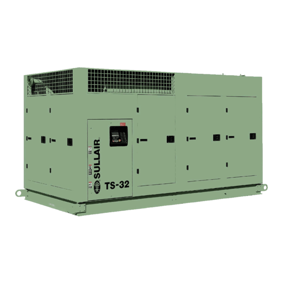
With a Sullair compressor, there is no capacity control system, and Supervisor control maintenance or inspection of the internal parts of the system, all mounted on a structural steel frame. - Page 12 TS32 USER MANUAL SECTION 2 Figure 2-1: Sullair Series TS32 Rotary Screw Compressor (Air-cooled Typical)
- Page 13 SECTION 2 TS32 USER MANUAL Figure 2-2: Sullair Series TS32 Rotary Screw Compressor (Water-cooled Typical)
-
Page 14: Compressor Cooling And Lubrication System, Function
TS32 USER MANUAL SECTION 2 After the air/fluid mixture is discharged from the down. When the compressor is operating, the fluid stop valve is held open by air pressure from the compressor unit, the fluid is separated from the air. compressor unit allowing a free flow of fluid from the At this time, the air flows to the service line and the separator/sump tank back to the compressor unit. - Page 15 SECTION 2 TS32 USER MANUAL Figure 2-3: Compressor Piping and Instrument Diagram (Typical)
- Page 16 TS32 USER MANUAL SECTION 2 Figure 2-4: Compressor Cooling and Lubrication System—Air-cooled...
- Page 17 SECTION 2 TS32 USER MANUAL Figure 2-5: Compressor Cooling and Lubrication System—Water-cooled...
- Page 18 TS32 USER MANUAL SECTION 2 Figure 2-6: Compressor Discharge System—Air-cooled 200-350HP...
- Page 19 SECTION 2 TS32 USER MANUAL Figure 2-7: Compressor Discharge System—Water-cooled 200-350HP...
- Page 20 TS32 USER MANUAL SECTION 2 Figure 2-8: Control System—START (Typical)
- Page 21 SECTION 2 TS32 USER MANUAL Figure 2-9: Control System—MODULATION (Typical)
- Page 22 TS32 USER MANUAL SECTION 2 Figure 2-10: Control System—UNLOAD (Typical)
- Page 23 SECTION 2 TS32 USER MANUAL Figure 2-11: Control System—FULL LOAD (Typical)
-
Page 24: Control System, Functional Description
100 TO 110 PSIG (6.9 TO 7.6 BAR) As air demand phases of compressor operation. The following drops below the rated capacity of the compressor, applies to TS32 Series compressors ranging from the line pressure will rise above 100 psig (6.9 bar). 400 through 600hp (298-447kw). For explanatory... -
Page 25: Air Inlet System, Functional Description
SECTION 2 TS32 USER MANUAL expands the diaphragm. The rack, in turn, engages spring in the actuator causes the spiral valve to with the pinion mounted on the spiral valve shaft return to the full load (maximum) position. assembly. This results in a rotary motion. As the AUTOMATIC OPERATION spiral valve rotates, it starts opening the bypass ports gradually. - Page 26 TS32 USER MANUAL SECTION 2 Figure 2-12: Compressor Air Inlet System...
-
Page 27: Table Of Specifications—Ts32
TS32 USER MANUAL Section 3 SPECIFICATIONS TABLE OF SPECIFICATIONS—TS32 DIMENSIONS (I) Length Width Height Weight Model TS32 AC 50/60 (II) TS32 WC 50/60 (II) (I) Dimensions for enclosed model (II) Consult factory. NOTE Noise levels vary with machine and enclo- sure. -
Page 28: Motor Specifications
Refer to Figure 3-1. Sullube fluid should be changed every 8000 hours or once a year, whichever comes Sullair encourages the user to participate in a fluid first. The fluid should be changed more frequently analysis program with the fluid suppliers. This could... -
Page 29: Lubrication Guide—24Kt Compressors
Sullair 24KT fluid. hours or once a year, whichever comes first. The Sullair recommends that a 24KT sample be taken at fluid should be changed more frequently under the first filter change and sent to the factory for severe operating conditions, such as high ambient analysis. - Page 30 Figure 3-2: Identification—Air-Cooled 02250126-376 R02...
- Page 31 Figure 3-0: Identification—Air-Cooled INSTALLATION NOTE: A FOUNDATION OR MOUNTING CAPABLE OF SUPPORTING THE WEIGHT ( 12,670# ) OF THE MACHINE AND RIGID ENOUGH TO MAIN- TAIN THE COMPRESSOR FRAME LEVEL AND THE COMPRESSOR IN ALIGNMENT IS REQUIRED. THE COMPRESSOR FRAME MUST BE LEV- ELED AND SECURED WITH FOUNDATION BOLTS, AND FULL UNIFORM CONTACT MUST BE MAINTAINED BETWEEN THE FRAME AND FOUN- DATION.
- Page 32 Figure 3-2: Identification—Water-Cooled 02250126-378 R03...
- Page 33 Figure 3-2: Identification—Water-Cooled INSTALLATION NOTE: A FOUNDATION OR MOUNTING CAPABLE OF SUPPORTING THE WEIGHT ( 12,160# ) OF THE MACHINE AND RIGID ENOUGH TO MAIN- TAIN THE COMPRESSOR FRAME LEVEL AND THE COMPRESSOR IN ALIGNMENT IS REQUIRED. THE COMPRESSOR FRAME MUST BE LEV- ELED AND SECURED WITH FOUNDATION BOLTS, AND FULL UNIFORM CONTACT MUST BE MAINTAINED BETWEEN THE FRAME AND FOUN- DATION.
- Page 34 Figure 3-3: Piping and Instrumentation Diagram—Air-Cooled 02250179-499 R01...
- Page 35 Figure 3-3: Piping and Instrumentation Diagram—Air-Cooled PART NO. PART NO. PART NO. PART NO. DESCRIPTION DESCRIPTION 200/250HP 300/350HP 200/250HP 300/350HP 250006-718 250006-718 1 FLTR,INL OPTIMALAIR 02250125-221 02250125-221 1 VLV,BALL 3/4"SAE X 3/4"NPT 02250126-220 02250126-220 1 VLV,10" INL BTFLY TS32C 250029-330 250029-330 1 VLV,RLF 2"...
- Page 36 Figure 3-4: Piping and Instrumentation Diagram—Air-Cooled (Continued) 02250179-499 R01...
- Page 37 Figure 3-4: Piping and Instrumentation Diagram—Air-Cooled NOTES: COMP DESCRIPTION PART NUMBERS ARE FOR REFERENCE ONLY. REFER TO BILL OF WET SUMP PRESSURE MATERIAL AND OR FACE OF ORDER FOR ACTUAL PARTS. LINE PRESSURE SECTION BETWEEN LETTERED POINTS ARE TO BE REPLACED INJECTION FLUID PRESSURE WITH CORRESPONDING OPTION PICTURED BELOW, AS HIGH PRESSURE SIDE OF FLUID FILTER...
- Page 38 Figure 3-5: Piping and Instrumentation Diagram—Remote Air-Cooled 02250179-498 R01...
- Page 39 Figure 3-5: Piping and Instrumentation Diagram—Remote Air-Cooled PART NO. DESCRIPTION PART NO. DESCRIPTION 250006-718 FLTR,INL OPTIMALAIR 02250120-955 VLV,THRM 180 DEG 2.5IN SAE 02250126-220 VLV,10" INL BTFLY TS32C 02250121-638 FLTR,2.5-12 SAE CORELESS 011682-003 CONTROL, SULLICON LESS BRKT 02250132-934 ORF,CAP 031 X 1/4"NPT 408893 VALVE, SHUTTLE 1/4"...
- Page 40 Figure 3-5: Piping and Instrumentation Diagram—Remote Air-Cooled (Continued) 02250179-498 R01...
- Page 41 SOL2 SPIRAL CONTROL SOLENOID VALVE (OPTIONAL) REQUIREMENTS. SOL3 START CONTROL SOLENOID VALVE (OPTIONAL) ITEM 39 OR 41 TO BE INSTALLED BY SULLAIR BUT ELECTRI- CALLY INSTALLED BY THE CUSTOMER IN THE FIELD. MEC/SEQUENCING/FULL LOAD SOLENOID VALVE SOL4 (OPTIONAL) THE SUPPLY AND RETURN PIPING FOR THE FLUID COOLER...
- Page 42 Figure 3-6: Piping and Instrumentation Diagram—Water-Cooled 02250179-496 R01...
- Page 43 Figure 3-6: Piping and Instrumentation Diagram—Water-Cooled PART NO. DESCRIPTION PART NO. DESCRIPTION 400 HP 500/600 HP PARTS LIST (BILL OF MATERIAL) 400 HP 500/600 HP PARTS LIST (BILL OF MATERIAL) 250006-718 250006-718 FLTR,INL OPTIMALAIR 02250127-343 02250127-343 SA,THRM VLV 190 DEG 02250126-220 02250126-220 VLV,10"...
- Page 44 Figure 3-6: Piping and Instrumentation Diagram—Water-Cooled (Continued) 02250179-496 R01...
- Page 45 Figure 3-6: Piping and Instrumentation Diagram—Water-Cooled COMP DESCRIPTION NOTES: WET SUMP PRESSURE PART NUMBERS ARE FOR REFERENCE ONLY. REFER TO BILL OF LINE PRESSURE MATERIAL AND OR FACE OF ORDER FOR ACTUAL PARTS. INJECTION FLUID PRESSURE SECTION BETWEEN LETTERED POINTS ARE TO BE REPLACED HIGH PRESSURE SIDE OF FLUID FILTER WITH CORRESPONDING OPTION PICTURED BELOW, AS REQUIRED BY FACE OF ORDER.
- Page 46 Figure 3-7: Wiring Diagram—Water-Cooled Wye Delta 02250178-841 R01...
- Page 47 Figure 3-7: Wiring Diagram—Water-Cooled Wye Delta COMP DESCRIPTION COMP DESCRIPTION COMPRESSOR MOTOR STARTER INTERNAL Y-DELTA RELAY CONTACT 1MOL COMPRESSOR MOTOR STARTER OVERLOAD CONTACT INTERNAL LOAD CONTROL RELAY CONTACT COMPRESSOR MOTOR STARTER RUN CONTACTOR INTERNAL SEQUENCE RELAY CONTACT COMPRESSOR START CONTACTOR INTERNAL ELECTRIC DRAIN RELAY CONTACT FAN MOTOR STARTER INTERNAL COMMON FAULT RELAY CONTACT...
- Page 48 Figure 3-8: Wiring Diagram—Air-Cooled Full Voltage 02250178-845 R01...
- Page 49 Figure 3-8: Wiring Diagram—Air-Cooled Full Voltage COMP DESCRIPTION COMP DESCRIPTION COMPRESSOR MOTOR STARTER CONTACT OPT'L AUDIBLE ALARM 1MOL COMPRESSOR MOTOR STARTER OVERLOAD CONTACT HTR1 SUMP HEATER HTR2 HEAT TRACE COMPRESSOR MOTOR STARTER RUN CONTACTOR HTR3 TRAP HEATER 2MOL FAN MOTOR STARTER OVERLOAD CONTACT HTR4 CONTROL PANEL HEATER TRANSFORMER PRIMARY FUSES...
- Page 50 Figure 3-9: Wiring Diagram—Air-Cooled SSRV 02250178-844 R03...
- Page 51 Figure 3-9: Wiring Diagram—Air-Cooled SSRV COMP DESCRIPTION COMP DESCRIPTION COMPRESSOR MOTOR STARTER INTERNAL ELECTRIC DRAIN RELAY CONTACT 1MOL COMPRESSOR MOTOR STARTER OVERLOAD CONTACT INTERNAL COMMON FAULT RELAY CONTACT CANOPY FAN STARTER INTERNAL COMMON WARNING RELAY CONTACT 2MOL FAN MOTOR STARTER OVERLOAD CONTACT INTERNAL SPECIAL FUNCTION CONTACT 3MOL FAN MOTOR STARTER OVERLOAD CONTACT...
- Page 52 Figure 3-10: Wiring Diagram—Remote Air-Cooled Wye Delta 02250178-836 R01...
- Page 53 Figure 3-10: Wiring Diagram—Remote Air-Cooled Wye Delta COMP DESCRIPTION COMP DESCRIPTION COMPRESSOR MOTOR STARTER 1XFMR CONTROL VOLTAGE TRANSFORMER 1MOL COMPRESSOR MOTOR STARTER OVERLOAD CONTACT 2XFMR SUPERVISOR 3 STEPDOWN TRANSFORMER 24VAC COMPRESSOR MOTOR STARTER RUN CONTACTOR INTERNAL RUN RELAY CONTACT COMPRESSOR START CONTACTOR INTERNAL Y-DELTA RELAY CONTACT FAN MOTOR STARTER INTERNAL LOAD CONTROL RELAY CONTACT...
- Page 54 NOTES...
-
Page 55: Compressor Mounting— Support And Location
Consult Sullair Cus- compressor frame must be leveled and secured with tomer Care regarding operation on sub- foundation bolts, and full uniform contact must be freezing temperatures. - Page 56 (normally closed), controlled by the com- pressor control circuit, should be con- nected to the compressor’s water outlet. NOTE (Contact Sullair Customer Care for assis- tance.) The “waste heat” from air-cooled com- pressors can be used for local space Table 4-1: Water Flow Requirements heating.
- Page 57 SECTION 4 TS32 USER MANUAL Table 4-2: Ventilation Requirements WATER COOLED OR REMOTE COOLED COMPRESSOR AIR-COOLED (I) COOLING PACKAGE PACKAGE VENT MOTOR HEAT REJECTION HEAT REJECTION MODEL AIR FLOW CFM HP/KW BTU/HR FLOW (II) BTU/HR TS32-200 200/150 47,620 4150 560,200 18,000 TS32-250 250/187...
- Page 58 EAWATER OOLED YSTEMS The cooling system should be set up to limit damage A strainer must be installed in the system’s inlet from oil cooler leaks: piping to ensure the supply water is clean. Sullair also recommends installing solenoid valve •...
- Page 59 SECTION 4 TS32 USER MANUAL • Sheltered air-cooled machines must have UTDOOR NSTALLATION HELTERED their exhaust air vented outside of the Compressor packages installed in locations where enclosure. they will be exposed to outside elements must be • Installations consisting of more than one equipped with a TEFC motor.
- Page 60 These iary receiver tank may need to have their valves should have drip legs that drain at an angle response times adjusted. Contact Sullair downward from the base. A vent to the piping should Customer Care for assistance.
-
Page 61: Service Air Piping
SECTION 4 TS32 USER MANUAL Figure 4-2: Fluid Fill Location SERVICE AIR PIPING Service air piping should be installed as shown in CAUTION Figure 4-1. A shut-off valve should be installed to isolate a compressor from the service line if required. Also notice that the service line should be equipped DO NOT overfill. -
Page 62: Fluid Piping (Remote Air-Cooled Option Only
1. Check incoming voltage. Be sure that the for the compressor. The fluid necessary to fill this incoming voltage is the same voltage that the piping may be ordered from the nearest Sullair compressor was wired for. Verify that control representative or the representative from whom the transformer primary is wired for correct line compressor was purchased. -
Page 63: Introduction
OPERATION INTRODUCTION PURPOSE OF CONTROLS— INTRODUCTION While Sullair has built into the TS32 Series package a comprehensive array of controls and indicators to Indicators and functions included in the package are assure its proper operation, the user should listed in the following guide. However, all Supervisor... - Page 64 NOTES DISCHARGE CHECK VALVE Blocks the reverse flow of air/fluid through the compressor unit during shutdown. MINIMUM PRESSURE VALVE Maintains 50 psig (3.5 bar) in the separator/sump tank when the compressor is running loaded. Also incorporates a check valve, which prevents compressed air backflow from the system when unloaded or shutdown.
-
Page 65: Initial Start-Up Procedure
SECTION 5 TS32 USER MANUAL INITIAL START-UP 7. Slowly close the shut-off valve to assure PROCEDURE proper nameplate pressure unload setting is correct. The compressor will unload at The following procedure should be used to make the nameplate pressure. If adjustments are nec- essary, see Control System Adjustments. - Page 66 TS32 USER MANUAL SECTION 5 Figure 5-1: Supervisor Control Panel NOTE For information concerning all aspects of the Supervisor Controller, consult the Supervisor Controller manual 02250146- 049.
- Page 67 TS32 USER MANUAL Section 6 MAINTENANCE GENERAL MAINTENANCE AFTER INITIAL 50 HOURS OF OPERATION As you proceed in reading this section, it will be easy to see that the Maintenance Program for the air compressor is quite minimal yet important. The use After the initial 50 hours of operation, a few of the service indicators provided for the fluid filter, maintenance requirements are needed to rid the...
-
Page 68: Parts Replacement And Adjustment Procedures
TS32 USER MANUAL SECTION 6 compressor and the fluid stop valve. When servicing the main filter, shut the compressor down, be sure all pressure has been released, then follow the instructions below. For element replacement order kit number 02250139-996. 1. Drain the fluid from the canister by removing the bottom drain plug 2. - Page 69 SECTION 6 TS32 USER MANUAL Figure 6-2: Air Filter Replacement (P/N 250006-718) *Primary Replacement Element Kit P/N 02250135-149 **Secondary Replacement Element Kit P/N 25007-839 6. Clean the interior of the housing by using a damp cloth. DO NOT blow dirt out with com- LEMENT EMOVAL pressor air.
- Page 70 TS32 USER MANUAL SECTION 6 3. If the clean element is to be stored for later use, it must be stored in a clean, closed con- tainer. 4. After the element has been installed, inspect and tighten, if necessary, all air inlet connec- tions prior to resuming operation.
- Page 71 SECTION 6 TS32 USER MANUAL Figure 6-4: Fluid Return / Sight Glass (I) Replacement Filter Assembly P/N 02250117-782 9. Clean the underside of the separator tank Order filter assembly no. 02250117- 782, and use cover and remove any rust. the following instructions as a guide. 10.
- Page 72 TS32 USER MANUAL SECTION 6 IFFERENTIAL RESSURE EGULATOR DJUSTMENT Refer to Figure 6-5 and Figure 6-6. The differential pressure regulators are adjusted by loosening the jam nut on the end of the cone shaped cover of the pressure regulator. When the jam nut is loose, turn the adjusting screw clockwise to increase or counterclockwise to decrease the setting.
-
Page 73: Drive Coupling Installation And Alignment
SECTION 6 TS32 USER MANUAL STEP 2 OFFSET ALIGNMENT HAFT OUPLING AINTENANCE Clean any oil, grease, dirt or paint from coupling The compressor unit and motor are rigidly connected faces and the other surfaces of the drive flanges. through mounting adapter housing. - Page 74 TS32 USER MANUAL SECTION 6 Table 6-1, tighten the motor mounting bolts and STEP 4 INSTALL THE FLEXIBLE ELEMENT recheck the offset and angular alignment. If the Refer to shaft coupling maintenance for installation of vertical angular alignment is not within specifications, drive coupling element.
-
Page 75: Troubleshooting— Introduction
Should your problem persist after making the recommended check, consult your nearest Sullair In addition to the Troubleshooting Guide, consult the representative. Supervisor Controller manual additional... - Page 76 TS32 USER MANUAL SECTION 6 Table 6-2: Troubleshooting Guide SYMPTOM PROBABLE CAUSE REMEDY Compressor Shuts Down With HIGH TEMP T1 or T3 Message Cooling water temperature too high; increase Air Demand Present (continued) Displayed water flow (water-cooled only). Cooling water flow insufficient; check water lines, valves (water-cooled only) and available water pressure differential.
- Page 77 SECTION 6 TS32 USER MANUAL Table 6-2: Troubleshooting Guide SYMPTOM PROBABLE CAUSE REMEDY Line Pressure Rises Above Leak in control system causing Check for leaks. Unload P2 Pressure Setting On loss of pressure signals The Supervisor Defective Solenoid Valve Check that inlet valve closes when Supervisor is in NO LOAD mode.
- Page 78 NOTES...
- Page 79 NOTES...
- Page 80 Zone Des Granges BP 82 Chiwan, Shekou Michigan City, Indiana, 46360 U.S.A. 42602 Montbrison, France Shenzen, Guangdong PRV. www.sullair.com Telephone: 33-477968470 PRC POST CODE 518068 Telephone: 1-800-SULLAIR (U.S.A. only) Fax: 33-477968499 Telephone: 755-6851686 Fax: 219-874-1273 www.sullaireurope.com Fax: 755-6853473 CUSTOMER CARE www.sullair-asia.com...
Need help?
Do you have a question about the TS32 Series and is the answer not in the manual?
Questions and answers