Table of Contents
Advertisement
USER MANUAL
I
NDUSTRIAL
WARRANTY NOTICE
Failure to follow the instructions
and procedures in this manual or,
misuse of this equipment will
VOID its warranty!
A
IR
TS20C/V200TS
C
OMPRESSOR
V
PART NUMBER:
02250184-783 R00
KEEP FOR
FUTURE
REFERENCE
SULLAIR CORPORATION
©
The information in this manual is current
as of its publication date, and applies to
compressor serial number:
200910010000
and all subsequent serial numbers.
Advertisement
Table of Contents

Related Manuals for Sullair TS20C


Summary of Contents for Sullair TS20C
- Page 1 USER MANUAL NDUSTRIAL OMPRESSOR TS20C/V200TS PART NUMBER: 02250184-783 R00 KEEP FOR FUTURE WARRANTY NOTICE REFERENCE SULLAIR CORPORATION © Failure to follow the instructions The information in this manual is current and procedures in this manual or, as of its publication date, and applies to...
- Page 2 AIR CARE SEMINAR TRAINING Sullair Air Care Seminars are courses that provide hands-on instruction for the proper operation, maintenance, and servicing of Sullair products. Individual seminars on Industrial compressors and compressor electrical systems are offered at regular intervals throughout the year at Sullair’s corporate headquarters training facility located at Michigan City, Indiana.
-
Page 3: Table Of Contents
SECTION 2—DESCRIPTION INTRODUCTION COMPRESSOR COMPONENT DESCRIPTION COMPRESSOR COOLING AND LUBRICATION SYSTEM—FUNCTION- AL DESCRIPTION COMPRESSOR DISCHARGE SYSTEM—FUNCTIONAL DESCRIPTION CONTROL SYSTEM— FUNCTIONAL DESCRIPTION FOR TS20C CONTROL SYSTEM— FUNCTIONAL DESCRIPTION V200TS AIR INLET SYSTEM— FUNCTIONAL DESCRIPTION SECTION 3—SPECIFICATIONS TABLE OF SPECIFICATIONS—TS-20C TABLE OF SPECIFICATIONS—V200TS... - Page 4 TABLE OF CONTENTS SECTION 4—INSTALLATION COMPRESSOR MOUNTING— SUPPORT AND LOCATION VENTILATION AND COOLING SERVICE AIR PIPING COUPLING ALIGNMENT CHECK FLUID LEVEL CHECK ELECTRICAL PREPARATION MOTOR ROTATION DIRECTION CHECK SECTION 5—SUPERVISOR CONTROLLER SECTION 6—MAINTENANCE GENERAL DAILY OPERATION MAINTENANCE AFTER INITIAL 50 HOURS OF OPERATION MAINTENANCE EVERY 2000 HOURS FLUID MAINTENANCE FLUID FILTER MAINTENANCE...
-
Page 5: Section 1-Safety
GENERAL tions relative to personal protective equipment, such as eye and face protective equipment, Sullair Corporation and its subsidiaries design and respiratory protective equipment, equipment manufacture all of their products so they can be intended to protect the extremities, protective operated safely. -
Page 6: Fire And Explosion
SECTION 1 inside diameter to reduce pressure in case of accumulate on, under or around acoustical mate- hose failure. rial, or on any external surfaces of the air com- pressor. Wipe down using an aqueous industrial D. Flow-limiting valves are listed by pipe size and cleaner or steam clean as required. -
Page 7: Hot Surfaces, Sharp Edges And Sharp Corners
SECTION 1 C. Wear snug-fitting clothing and confine long hair when working around this compressor, especially DANGER when exposed to hot or moving parts. D. Keep access doors, if any, closed except when making repairs or adjustments. E. Make sure all personnel are out of and/or clear of the compressor prior to attempting to start or operate it. -
Page 8: Electrical Shock
SECTION 1 swallowed, induce vomiting by administering a tablespoon of salt, in each glass of clean, warm water until vomit is clear, then administer two DANGER teaspoons of baking soda in a glass of clean water. Have patient lay down and cover eyes to exclude light. -
Page 9: 1.10 Entrapment
SECTION 1 Keep lift operator in constant attendance when- N. Make sure pallet-mounted compressors are ever compressor is suspended. firmly bolted or otherwise secured to the pallet prior to attempting to forklift or transport them. J. Set compressor down only on a level surface NEVER attempt to forklift a compressor that is capable of safely supporting at least its weight not secured to its pallet, as uneven floors or sud-... - Page 10 NOTES...
-
Page 11: Introduction
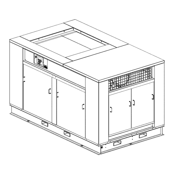
DESCRIPTION INTRODUCTION COMPRESSOR COMPONENT DESCRIPTION The design of the Sullair TS20C/V200TS compressor unit is a two stage, positive displacement, flood The components and assemblies of the air lubricated one. A complete package includes the: compressors are clearly shown. The complete... - Page 12 TS20C USER MANUAL SECTION 2 Figure 2-1: Sullair Rotary Screw Air Compressor- Air-Cooled 100/150HP...
- Page 13 SECTION 2 TS20C USER MANUAL Figure 2-2: Sullair Rotary Screw Air Compressor- Air-Cooled 200HP...
- Page 14 TS20C USER MANUAL SECTION 2 Figure 2-3: Sullair Rotary Screw Air Compressor- Air-Cooled 250HP...
- Page 15 SECTION 2 TS20C USER MANUAL Figure 2-4: Sullair Rotary Screw Air Compressor- Air-Cooled 200HP with Mounted VSD...
- Page 16 TS20C USER MANUAL SECTION 2 Figure 2-5: Air-Cooled, Cooling/Lubrication and Discharge System AA: FROM UNIT DISCHARGE CHECK VALVE 1. FLUID FILTER 2. FLUID STOP VALVE BB: TO FLUID COOLER 3. MINIMUM PRESSURE CHECK VALVE CC: FROM FLUID COOLER 4. AIR/FLUID SUMP/SEPARATOR TANK DD: TO UNIT INJECTION 5.
-
Page 17: Compressor Cooling And Lubrication System-Function
SECTION 2 TS20C USER MANUAL COMPRESSOR COOLING 3. Houses the air/fluid separator elements. AND LUBRICATION The compressed air/fluid mixture enters the sump SYSTEM—FUNCTIONAL tank and flows through an internal baffle system that DESCRIPTION changes the flow’s direction and velocity, which causes most of the fluid to fall to the bottom of the Refer to Figure 2-5. -
Page 18: Control System- Functional Description For Ts20C
TS20C USER MANUAL SECTION 2 CONTROL SYSTEM— MODULATING MODE WITH SPIRAL VALVE—100 FUNCTIONAL DESCRIPTION TO 110 PSIG (6.9 TO 7.6 BAR) FOR TS20C As air demand drops below the rated capacity of the compressor, the line pressure will rise above 100 Refer to Figure 2-9. -
Page 19: Control System- Functional Description V200Ts
NOTES CONTROL SYSTEM— the blowdown valve to close. The re-energized FUNCTIONAL DESCRIPTION solenoid valve again prevents line pressure from V200TS reaching the inlet control valve. Should the pressure begin to rise, the pressure regulator will resume its The purpose of the compressor control system is to normal function as previously described. - Page 20 TS20C USER MANUAL SECTION 2 Supervisor Controller will automatically set the to the spiral valve actuator. This in turn expands the diaphragm and engages the pinion mounted on the frequency range based on the selected pressure. For spiral valve shaft assembly, resulting in a rotary...
- Page 21 SECTION 2 TS20C USER MANUAL there requirements, Supervisor’s requirement is present and restart as compressed air AUTOMATIC mode allows the compressor to is needed. shutdown (time delayed) when no compressed air...
-
Page 22: Air Inlet System- Functional Description
TS20C USER MANUAL SECTION 2 AIR INLET SYSTEM— FUNCTIONAL DESCRIPTION Refer to Figure 2-9. The compressor inlet system consists of a dry-type air filter and an air inlet valve. A poppet-type modulating air inlet valve directly controls the amount of air intake to the compressor in response to the operation of the pressure regulator (see MODULATING MODE WITH SPIRAL VALVE—... - Page 23 NOTES...
- Page 24 Figure 2-9: TS20C Piping and Instrumentation 100/150HP 02250177-307 R02...
- Page 25 Figure 2-9: TS20C Piping and Instrumentation 100/150HP PART NO. DESCRIPTION PART NO. DESCRIPTION 02250135-154 FILTER,AIR 15” DIA. 02250117-782 STRAINER,V-TYPE 1/4” 300PSI (2.1 BAR) 02250145-632 VALVE,INLET 6” W/BYPASS 250017-280 VALVE, PRESSURE REGULATOR COMPRESSOR,UNIT TS20C 02250100-042 VLV, 1/2 BLDWN 1.8:1 250 PSIG...
- Page 26 Figure 2-9: TS20C Piping and Instrumentation 100/150HP (continued) 02250177-307 R02...
- Page 27 Figure 2-9: TS20C Piping and Instrumentation 100/150HP NOTES: COMPONENT DESCRIPTION WET SUMP PRESSURE PART NUMBERS ARE FOR REFERENCE ONLY. REFER TO BILL OF MATERIAL AND OR FACE OF ORDER FOR ACTUAL PARTS. LINE PRESSURE SECTION BETWEEN LETTERED POINTS ARE TO BE REPLACED...
- Page 28 Figure 2-10: TS20C Piping and Instrumentation 200-250HP 02250177-308 R02...
- Page 29 Figure 2-10: TS20C Piping and Instrumentation 200-250HP PART NO. DESCRIPTION PART NO. DESCRIPTION 02250140-798 FILTER,INL OPTIMALAIR 16" DIA. 42694 VALVE,CHECK 1/2” 02250161-157 VALVE,INLET 8” W/ALUM SLV 02250110-557 VALVE,CHECK 1/4” COMPRESSOR,UNIT TS20C 02250148-608 VALVE,PRESSURE REG. 1/4” NPT 70-25-# VALVE,SPIRAL 02250052-358 VALVE,REGULATOR BACKPRESSURE CTL 1/4”...
- Page 30 Figure 2-10: TS20C Piping and Instrumentation 200-250HP (continued) 02250177-308 R02...
- Page 31 Figure 2-10: TS20C Piping and Instrumentation 200-250HP NOTES: COMPONENT DESCRIPTION PART NUMBERS ARE FOR REFERENCE ONLY. REFER TO BILL WET SUMP PRESSURE OF MATERIAL AND OR FACE OF ORDER FOR ACTUAL PARTS. LINE PRESSURE SECTION BETWEEN LETTERED POINTS ARE TO BE REPLACED...
- Page 32 Figure 2-11: TS20C Piping & Instrumentation 250HP INTAC 02250177-313- R03...
- Page 33 Figure 2-11: TS20C Piping & Instrumentation 250HP INTAC PART NO. DESCRIPTION PART NO. DESCRIPTION 02250140-798 FILTER,INL OPTIMALAIR 16” DIA. 42694 VALVE,CHECK 1/2” 02250161-157 VALVE,INLET 8” W/ALUM SLV 02250110-557 VALVE,CHECK 1/4” COMPRESSOR,UNIT TS20C 02250148-608 VALVE,PRESSURE REG. 1/4” NPT 70-25-# VALVE,SPIRAL 02250052-358 VALVE,REGULATOR BACKPRESSURE CTL 1/4”...
- Page 34 Figure 2-11: TS20C Piping & Instrumentation 250HP INTAC (continued) 02250177-313- R03...
- Page 35 Figure 2-11: TS20C Piping & Instrumentation 250HP INTAC NOTES: COMPONENT DESCRIPTION PART NUMBERS ARE FOR REFERENCE ONLY. REFER TO BILL WET SUMP PRESSURE OF MATERIAL AND OR FACE OF ORDER FOR ACTUAL PARTS. SECTION BETWEEN LETTERED POINTS ARE TO BE REPLACED...
- Page 36 Figure 2-12: TS20C Piping and Instrumentation 100/150HP WCAC 02250177-309 R02...
- Page 37 Figure 2-12: TS20C Piping and Instrumentation 100/150HP WCAC PART NO. DESCRIPTION PART NO. DESCRIPTION 02250135-154 FILTER,AIR 15” DIA. 02250117-782 STRAINER,V-TYPE 1/4” 300PSI (2.1 BAR) 02250145-632 VALVE,INLET 6” W/BYPASS 250017-280 VALVE, PRESSURE REGULATOR COMPRESSOR,UNIT TS20C 02250100-042 VLV, 1/2 BLDWN 1.8:1 250 PSIG...
- Page 38 Figure 2-12: TS20C Piping and Instrumentation 100/150HP WCAC (continued) 02250177-309 R02...
- Page 39 Figure 2-12: TS20C Piping and Instrumentation 100/150HP WCAC MOISTURE SEPARATORS NOTES: PACKAGE PART # DESCRIPTION PART NUMBERS ARE FOR REFERENCE ONLY. REFER TO BILL H.P. OF MATERIAL AND OR FACE OF ORDER FOR ACTUAL PARTS. 100/125 02250166-742 SEP,WTR SCWS-740N 2” L/AD...
- Page 40 Figure 2-13: TS20C Piping and Instrumentation 200-250HP WCAC 02250177-310 R03...
- Page 41 Figure 2-13: TS20C Piping and Instrumentation 200-250HP WCAC PART NO. DESCRIPTION PART NO. DESCRIPTION 02250140-798 FILTER,INL OPTIMALAIR 16” DIA. 42694 VALVE,CHECK 1/2” 02250161-157 VALVE,INLET 8” W/ALUM SLV 02250110-557 VALVE,CHECK 1/4” COMPRESSOR,UNIT TS20C 02250148-608 VALVE,PRESSURE REG. 1/4” NPT 70-25-# VALVE,SPIRAL 02250052-358 VALVE,REGULATOR BACKPRESSURE CTL 1/4”...
- Page 42 Figure 2-13: TS20C Piping and Instrumentation 200-250HP WCAC (continued) 02250177-310 R03...
- Page 43 Figure 2-13: TS20C Piping and Instrumentation 200-250HP WCAC NOTES: COMPONENT DESCRIPTION PART NUMBERS ARE FOR REFERENCE ONLY. REFER TO BILL WET SUMP PRESSURE OF MATERIAL AND OR FACE OF ORDER FOR ACTUAL PARTS. SECTION BETWEEN LETTERED POINTS ARE TO BE REPLACED...
- Page 44 Figure 2-14: V200TS Piping and Instrumentation 100/150 INTAC 02250183-513 R01...
- Page 45 INDICATE SERIAL NUMBER OF COMPRESSOR 02250113-668 VALVE,FLUID STOP 1-5/8” SAE PORTS 02250155-174 XDCR,PRESS 0-250# RATIOMETRIC 02250175-087 P,THERMISTER 3000 OHM NTC 12’L 02250177-841 SA,DISCH CHK VLV TS20C 02250125-774 ORIFICE .031” (.79mm) 02250125-775 ORIFICE, .062” (1.58mm) 02250132-934 ORIFICE,CAP 1/4” NPT .031” DIA. (.79mm) 234125-313 ORIFICE, 1/2M X 1/2F X .313...
- Page 46 Figure 2-14: V200TS Piping and Instrumentation 100/150 INTAC (continued) 02250183-513 R01...
- Page 47 V200TS Piping and Instrumentation 100/150HP MOISTURE SEPARATORS NOTES: PACKAGE PART # DESCRIPTION PART NUMBERS ARE FOR REFERENCE ONLY. REFER TO BILL H.P. OF MATERIAL AND OR FACE OF ORDER FOR ACTUAL PARTS. 100/125 02250166-742 SEP,WTR SCWS-740N 2” L/AD SECTION BETWEEN LETTERED POINTS ARE TO BE REPLACED 02250166-743 SEP,WTR SCWS-1700N 2-1/2”...
- Page 48 Figure 2-15: V200TS Piping & Instrumentation 200HP INTAC 02250183-443 R01...
- Page 49 02250166-743 SEP,WTR SCWS-1700N 2-1/2” L/AD 02250182-545 DRN,ZERO LOSS 110V 1/2”NPT 02250127-119 HSG,THRMVLV 1-7/8” SAE 4 PORT 02250177-841 SA,DISCH CHK VLV TS20C 02250121-656 FILTER.FLUID SAE 2” FLG CORELESS 02250043-014 HTR,SUMP 1800W 120V PAD 29X19 02250113-668 VALVE,FLUID STOP 1-5/8” SAE PORTS 02250087-631...
- Page 50 Figure 2-16: V200TS Piping & Instrumentation 200HP INTAC (continued) 02250183-443 R01...
- Page 51 Figure 2-16: V200TS Piping & Instrumentation 200HP INTAC NOTES: COMPONENT DESCRIPTION PART NUMBERS ARE FOR REFERENCE ONLY. REFER TO BILL WET SUMP PRESSURE OF MATERIAL AND OR FACE OF ORDER FOR ACTUAL PARTS. SECTION BETWEEN LETTERED POINTS ARE TO BE REPLACED LINE PRESSURE WITH CORRESPONDING OPTION PICTURED BELOW, AS REQUIRED BY FACE OF ORDER.
- Page 52 Figure 2-17: V200TS Piping & Instrumentation 100/150HP WCAC 02250183-515 R01...
- Page 53 250017-992 SWITCH,LOW WATER PRESSURE 02250175-087 P,THERMISTER 3000 OHM NTC 12’L 02250051-913 VLV,RLF INTERSTAGE 65# 02250177-841 SA,DISCH CHK VLV TS20C Continued on page 51 02250125-774 ORIFICE .031” (.79mm) PLEASE NOTE: WHEN ORDERING PARTS, INDICATE SERIAL NUMBER OF COMPRESSOR 02250125-775 ORIFICE, .062” (1.58mm) 02250132-934 ORIFICE,CAP 1/4”...
- Page 54 Figure 2-17: V200TS Piping & Instrumentation 100/150HP WCAC (continued) 02250183-515 R01...
- Page 55 Figure 2-17: V200TS Piping & Instrumentation 100/150HP WCAC COMPONENT DESCRIPTION NOTES: WET SUMP PRESSURE PART NUMBERS ARE FOR REFERENCE ONLY. REFER TO BILL LINE PRESSURE OF MATERIAL AND OR FACE OF ORDER FOR ACTUAL PARTS. INJECTION FLUID PRESSURE SECTION BETWEEN LETTERED POINTS ARE TO BE REPLACED HIGH PRESSURE SIDE OF FILTER WITH CORRESPONDING OPTION PICTURED BELOW, AS REQUIRED BY FACE OF ORDER.
- Page 56 Figure 2-18: V200TS Piping & Instrumentation 200HP WCAC 02250183-444 R02...
- Page 57 02250166-743 SEP,WTR SCWS-1700N 2-1/2” L/AD 02250182-545 DRN,ZERO LOSS 110V 1/2”NPT 02250127-119 HSG,THRMVLV 1-7/8” SAE 4 PORT 02250177-841 SA,DISCH CHK VLV TS20C 02250121-656 FILTER.FLUID SAE 2” FLG CORELESS 02250043-014 HTR,SUMP 1800W 120V PAD 29X19 02250113-668 VALVE,FLUID STOP 1-5/8” SAE PORTS 02250087-631...
- Page 58 Figure 2-18: V200TS Piping & Instrumentation 200HP WCAC (continued) 02250183-444 R02...
- Page 59 Figure 2-18: V200TS Piping & Instrumentation 200HP WCAC NOTES: COMPONENT DESCRIPTION PART NUMBERS ARE FOR REFERENCE ONLY. REFER TO BILL WET SUMP PRESSURE OF MATERIAL AND OR FACE OF ORDER FOR ACTUAL PARTS. SECTION BETWEEN LETTERED POINTS ARE TO BE REPLACED LINE PRESSURE WITH CORRESPONDING OPTION PICTURED BELOW, AS REQUIRED BY FACE OF ORDER.
- Page 60 Figure 2-19: TS20C Wiring Diagram MFV NC SUPV AC/WC 02250178-820 R02...
- Page 61 Figure 2-20: TS20C Wiring Diagram MFV NC SUPV AC/WC COMP DESCRIPTION COMP DESCRIPTION COMPRESSOR MOTOR INTERNAL LOAD CONTROL RELAY CONTACT 1MOL COMPRESSOR OVERLOAD INTERNAL SEQUENCE RELAY CONTACT COOLER FAN STARTER/CANOPY FAN ON WATER COOLED INTERNAL ELECTRIC DRAIN RELAY CONTACT 2MOL...
- Page 62 Figure 2-21: TS20C Wiring Diagram YD NC SUPV AC/WC 02250178-821 R02...
- Page 63 Figure 2-21: TS20C Wiring Diagram YD NC SUPV AC/WC COMP DESCRIPTION COMP DESCRIPTION COMPRESSOR MOTOR INTERNAL SEQUENCE RELAY CONTACT 1MOL COMPRESSOR OVERLOAD INTERNAL ELECTRIC DRAIN RELAY CONTACT COMPRESSOR RUN CONTACTOR INTERNAL COMMON FAULT RELAY CONTACT COOLER FAN STARTER/CANOPY FAN ON WATER COOLED...
- Page 64 Figure 2-22: TS20C SSRV NC SUPV AC/WC 02250178-822 R02...
- Page 65 Figure 2-22: TS20C SSRV NC SUPV AC/WC COMP DESCRIPTION COMP DESCRIPTION COMPRESSOR MOTOR INTERNAL LOAD CONTROL RELAY CONTACT 1MOL COMPRESSOR OVERLOAD INTERNAL SEQUENCE RELAY CONTACT COOLER FAN STARTER/CANOPY FAN ON WATER COOLED INTERNAL ELECTRIC DRAIN RELAY CONTACT 2MOL COOLER/CANOPY FAN MOTOR OVERLOAD INTERNAL COMMON FAULT RELAY CONTACT OPT’L POWER FACTOR CAPACITOR CONTACTOR...
- Page 66 Figure 2-23: TS20C CUST STR SUPV AC/WC 02250178-823 R02...
- Page 67 Figure 2-23: TS20C CUST STR SUPV AC/WC COMP DESCRIPTION COMP DESCRIPTION COMPRESSOR MOTOR INTERNAL LOAD CONTROL RELAY CONTACT 1MOL COMPRESSOR OVERLOAD INTERNAL SEQUENCE RELAY CONTACT COOLER FAN STARTER/CANOPY FAN ON WATER COOLED INTERNAL ELECTRIC DRAIN RELAY CONTACT 2MOL COOLER/CANOPY FAN MOTOR OVERLOAD...
- Page 68 Figure 2-24: TS20C MFV NC SUPV AC/RC 02250178-824 R02...
- Page 69 Figure 2-24: TS20C MFV NC SUPV AC/RC COMP DESCRIPTION COMP DESCRIPTION COMPRESSOR MOTOR INTERNAL ELECTRIC DRAIN RELAY CONTACT 1MOL COMPRESSOR OVERLOAD INTERNAL COMMON FAULT RELAY CONTACT COOLER FAN STARTER/CANOPY FAN ON WATER COOLED INTERNAL COMMON WARNING RELAY CONTACT 2MOL COOLER/CANOPY FAN MOTOR OVERLOAD...
- Page 70 Figure 2-25: TS20C MFV NC SUPV AC VSD FAN 02250178-825 R02...
- Page 71 Figure 2-25: TS20C MFV NC SUPV AC VSD FAN COMP DESCRIPTION COMP DESCRIPTION COMPRESSOR MOTOR OPT’L AUDIBLE ALARM 1MOL COMPRESSOR OVERLOAD HTR1 SUMP HEATER 2000 WATTS TRANSFORMER PRIMARY FUSES HTR2 HEAT TRACE TRANSFORMER SECONDARY FUSE HTR3 TRAP HEATER 50 WATTS...
- Page 72 NOTES...
-
Page 73: Table Of Specifications-Ts-20C
TS20C USER MANUAL Section 3 SPECIFICATIONS TABLE OF SPECIFICATIONS—TS-20C DIMENSIONS Length Width Height (I) Weight (II) Model TS-20C 3048 1828.8 1727.2 7350 3333.9 TS-20C 3048 1828.8 1727.2 7600 3447.3 TS-20C 3048 1828.8 1727.2 7900 3583.4 TS-20C 3048 1828.8 1727.2 8100 3674.1... -
Page 74: Motor Specifications
TS20C USER MANUAL SECTION 3 MOTOR SPECIFICATIONS MOTOR: (50 Hz Compressors) STANDARD MODELS: Size: 100-200 HP/75-150kW Open Dripproof, Three Phase, 50 Cycles, A.C., 104ºF Type: (40ºC) Maximum Ambient Temperature Starter: 400V Full Voltage Magnetic Speed: 1500 RPM MOTOR SPECIFICATIONS MOTOR: (60 Hz Compressors) -
Page 75: Application Guide
SECTION 3 TS20C USER MANUAL APPLICATION GUIDE Sulliar encourages its customers to participate in a NOTE fluid analysis program with the fluid suppliers. In some cases the analysis results suggest a fluid When performing a fluid change or topping change interval which differs from the User Manual. - Page 76 Figure 3-2: Identification—TS20C (Typical) 02250175-122 R03...
- Page 77 Identification—TS20C (Typical) NOTES PACKAGE WEIGHTS ALLOW 4' MINIMUM CLEARANCE AROUND MACHINE FOR WEIGHT WEIGHT PACKAGE WEIGHT W/O ACCESS AND FREE CIRCULATION OF AIR. W/BUSTLED HORSEPOWER ENCLOSURE ENCLOSURE ENCLOSURE A FOUNDATION OR MOUNTING CAPABLE OF SUPPORTING THE WEIGHT OF THE MACHINE AND RIGID ENOUGH TO MAINTAIN...
- Page 78 Figure 3-3: Identification—TS2C0-200HP AC 02250175-130 R03...
- Page 79 Identification—TS2C0-200HP AC NOTES ALLOW 4' MINIMUM CLEARANCE AROUND MACHINE FOR ACCESS AND FREE CIRCULATION OF AIR. A FOUNDATION OR MOUNTING CAPABLE OF SUPPORTING THE WEIGHT OF THE MACHINE AND RIGID ENOUGH TO MAINTAIN THE COMPRESSOR FRAME LEVEL AND THE COMPRESSOR IN ALIGNMENT IS REQUIRED.
- Page 80 Figure 3-4: Identification—TS20C 250HP AC 02250175-136 R02...
- Page 81 Identification—TS20C 250HP AC NOTES ALLOW 4' MINIMUM CLEARANCE AROUND MACHINE FOR ACCESS AND FREE CIRCULATION OF AIR. A FOUNDATION OR MOUNTING CAPABLE OF SUPPORTING THE WEIGHT OF THE MACHINE AND RIGID ENOUGH TO MAINTAIN THE COMPRESSOR FRAME LEVEL AND THE COMPRESSOR IN ALIGNMENT IS REQUIRED.
- Page 82 Figure 3-5: Identification—TS20C 100/150 WCAC SER 02250175-144 R03...
- Page 83 Identification—TS20C 100/150 WCAC SER NOTES ALLOW 4' MINIMUM CLEARANCE AROUND MACHINE FOR AIR OUTLET SIZE ACCESS AND FREE CIRCULATION OF AIR. PACKAGE AIR OUTLET A FOUNDATION OR MOUNTING CAPABLE OF SUPPORTING THE HORSEPOWER PORT SIZE WEIGHT OF THE MACHINE AND RIGID ENOUGH TO MAINTAIN THE COMPRESSOR FRAME LEVEL AND THE COMPRESSOR IN 2”...
- Page 84 Figure 3-6: Identification—TS20C 200HP WCAC SER 02250175-148 R03...
- Page 85 Identification—TS20C 200HP WCAC SER NOTES ALLOW 4' MINIMUM CLEARANCE AROUND MACHINE FOR ACCESS AND FREE CIRCULATION OF AIR. A FOUNDATION OR MOUNTING CAPABLE OF SUPPORTING THE WEIGHT OF THE MACHINE AND RIGID ENOUGH TO MAINTAIN THE COMPRESSOR FRAME LEVEL AND THE COMPRESSOR IN ALIGNMENT IS REQUIRED.
- Page 86 Figure 3-7: Identification—V200TS—100/150HP AC 02250182-109 R02...
- Page 87 Identification—V200TS—100/150HP AC NOTES ALLOW 4' MINIMUM CLEARANCE AROUND MACHINE FOR AIR OUTLET SIZE ACCESS AND FREE CIRCULATION OF AIR. PACKAGE AIR OUTLET A FOUNDATION OR MOUNTING CAPABLE OF SUPPORTING THE HORSEPOWER PORT SIZE WEIGHT OF THE MACHINE AND RIGID ENOUGH TO MAINTAIN THE COMPRESSOR FRAME LEVEL AND THE COMPRESSOR IN 2”...
- Page 88 Figure 3-8: Identification—V200TS—200HP AC MTD VSD 02250182-116 R03...
- Page 89 Identification—V200TS—200HP AC MTD VSD NOTES ALLOW 4' MINIMUM CLEARANCE AROUND MACHINE FOR ACCESS AND FREE CIRCULATION OF AIR. A FOUNDATION OR MOUNTING CAPABLE OF SUPPORTING THE WEIGHT OF THE MACHINE AND RIGID ENOUGH TO MAINTAIN THE COMPRESSOR FRAME LEVEL AND THE COMPRESSOR IN ALIGNMENT IS REQUIRED.
- Page 90 Figure 3-9: Identification—V200TS—150/200HP AC REM VSD 02250183-731 R01...
- Page 91 Identification—V200TS—V200TS—150/200HP AC REM VSD NOTES ALLOW 4' MINIMUM CLEARANCE AROUND MACHINE FOR ACCESS AND FREE CIRCULATION OF AIR. A FOUNDATION OR MOUNTING CAPABLE OF SUPPORTING THE WEIGHT OF THE MACHINE AND RIGID ENOUGH TO MAINTAIN THE COMPRESSOR FRAME LEVEL AND THE COMPRESSOR IN ALIGNMENT IS REQUIRED.
- Page 92 Figure 3-10: Identification—V200TS—100/150HP WC SER 02250182-112 R01...
- Page 93 Identification—V200TS—100/150HP WC SER NOTES ALLOW 4' MINIMUM CLEARANCE AROUND MACHINE FOR AIR OUTLET SIZE ACCESS AND FREE CIRCULATION OF AIR. PACKAGE AIR OUTLET A FOUNDATION OR MOUNTING CAPABLE OF SUPPORTING THE HORSEPOWER PORT SIZE WEIGHT OF THE MACHINE AND RIGID ENOUGH TO MAINTAIN THE COMPRESSOR FRAME LEVEL AND THE COMPRESSOR IN 2”...
- Page 94 Figure 3-11: Identification—V200TS—150 WCAC SER MTD VSD 02250184-027 R01...
- Page 95 Identification—V200TS—150 WCAC SER MTD VSD NOTES ALLOW 4' MINIMUM CLEARANCE AROUND MACHINE FOR ACCESS AND FREE CIRCULATION OF AIR. A FOUNDATION OR MOUNTING CAPABLE OF SUPPORTING THE WEIGHT OF THE MACHINE AND RIGID ENOUGH TO MAINTAIN THE COMPRESSOR FRAME LEVEL AND THE COMPRESSOR IN ALIGNMENT IS REQUIRED.
- Page 96 Figure 3-12: Identification—V200TS—200HP WCAC SER MTD VSD 02250183-725 R02...
- Page 97 Identification—V200TS—200HP WCAC SER MTD VSD NOTES ALLOW 4' MINIMUM CLEARANCE AROUND MACHINE FOR ACCESS AND FREE CIRCULATION OF AIR. A FOUNDATION OR MOUNTING CAPABLE OF SUPPORTING THE WEIGHT OF THE MACHINE AND RIGID ENOUGH TO MAINTAIN THE COMPRESSOR FRAME LEVEL AND THE COMPRESSOR IN ALIGNMENT IS REQUIRED.
- Page 98 Figure 3-13: Identification—V200TS—150/200 WCAC SER REM VSD 02250183-736 R01...
- Page 99 Identification—V200TS—150/200 WCAC SER REM VSD NOTES ALLOW 4' MINIMUM CLEARANCE AROUND MACHINE FOR ACCESS AND FREE CIRCULATION OF AIR. A FOUNDATION OR MOUNTING CAPABLE OF SUPPORTING THE WEIGHT OF THE MACHINE AND RIGID ENOUGH TO MAINTAIN THE COMPRESSOR FRAME LEVEL AND THE COMPRESSOR IN ALIGNMENT IS REQUIRED.
- Page 100 NOTES...
-
Page 101: Section 4-Installation
TS20C USER MANUAL Section 4 INSTALLATION COMPRESSOR MOUNTING— VENTILATION AND SUPPORT AND LOCATION COOLING A foundation or mounting capable of supporting the OOLED OMPRESSORS weight of the compressor, and rigid enough to An area with adequate space must be provided for maintain the compressor frame level and the the compressor and its components. - Page 102 ATER OOLED OMPRESSORS the fan does not exceed 0.2 in W.C. Consult a Sullair Adequate cooling water flow must be supplied to office for assistance in utilizing this heat. If ductwork water-cooled compressors. Water delivery must be is added, the high static fan option is required.
- Page 103 SECTION 4 TS20C USER MANUAL Table 4-2: Ventilation Requirements (Typical) Water-Cooled Cooling Type Air-Cooled Motor HP/Kw: 100/75 125/93 150/112 200/150 250/187 100/75 125/93 150/112 200/150 250/187 Vent Fan Flow 10000 14000 14000 17000 22000 2,370 (I) 2,370 (I) 2,370 (I) 2,370 (I) 2,370 (I)
- Page 104 TS20C USER MANUAL SECTION 4 to Table 4-3: Water Tests. Table 4-3: Water Tests Substances Test Interval Acceptable Concentration Corrosivity Hardiness, pH, Total Dis- Monthly-if stable for 3 to 4 months, Langerlier Index 0 to 1 solved Solids, Temperature at inlet,...
-
Page 105: Service Air Piping
SECTION 4 TS20C USER MANUAL required, isolation valves should be installed close to UTDOOR NSTALLATION HELTERED discharge of the compressor. They should be Many times a compressor must be installed outside installed with drip legs that drain sloping downward due to available space or other jobsite conditions. -
Page 106: Electrical Preparation
TS20C USER MANUAL SECTION 4 ELECTRICAL PREPARATION 1. Check incoming voltage. The incoming voltage must match the compressor’s wire rating/specifications. Interior electrical wiring is installed at the factory. Required customer wiring should be done by a 2. Check motor starting device and overload qualified electrician in compliance with OSHA, heater sizes. - Page 107 SECTION 4 TS20C USER MANUAL...
- Page 108 NOTES...
-
Page 109: Section 5-Supervisor Controller
TS20C USER MANUAL Section 5 SUPERVISOR CONTROLLER Figure 5-1: Supervisor Control Panel NOTE For information concerning all aspects of the Supervisor Controller, consult the Supervisor Controller manual no. 02250179-965. - Page 110 NOTES...
-
Page 111: Section 6-Maintenance
TS20C USER MANUAL Section 6 MAINTENANCE GENERAL MAINTENANCE AFTER INITIAL 50 HOURS OF OPERATION WARNING After the initial 50 hours of operation, a few maintenance actions are required to clean the Before any repairs are attempted, refer to system of any foreign materials. Perform the Section 1: Safety before proceeding. -
Page 112: Fluid Filter Maintenance
TS20C USER MANUAL SECTION 6 FLUID FILTER MAINTENANCE Refer to Figure 6-1 & Figure 6-2. Replace the fluid filter element under any of the following conditions, or whichever occurs first: 1. Every 2000 hours. 2. When the Supervisor™ panel indicates high differential pressure. -
Page 113: Air Filter Maintenance
SECTION 6 TS20C USER MANUAL AIR FILTER MAINTENANCE LEMENT NSPECTION 1. Place a bright light inside the element to Refer to Figure 6-3 & Figure 6-4. Air filter inspect for damage or leak holes. Concen- maintenance on air filter no. 02250140-798 should trated light will shine through the element, be performed when the Supervisor™... -
Page 114: Separator Maintenance
TS20C USER MANUAL SECTION 6 LEMENT EPLACEMENT Figure 6-4: Air Filter Assembly, 200-250 1. Housing 2. Element (I) 3. Dust Collector 4. Sealing Washer (I) Element Replacement Kit P/N 02250135-155 Element replacement is performed by reversing the removal instructions. Make sure that the element is fully seated into the housing. - Page 115 SECTION 6 TS20C USER MANUAL 6. Inspect the sump tank for rust, dirt, etc. 7. DO NOT remove the grounding staples from the gaskets. DO NOT use any type of gasket CAUTION eliminator. Re-insert the separator elements with the gaskets attached into the sump tank...
-
Page 116: Fluid Return/Sight Glass Maintenance
TS20C USER MANUAL SECTION 6 FLUID RETURN/SIGHT GLASS MAINTENANCE Refer to Figure 6-6. The fluid return/sight glass subassembly is located on the side of the sump tank. Fluid return/sight glass maintenance should be performed along with that of the fluid filter. Order filter assembly no. -
Page 117: Pressure Regulator Adjustment
SECTION 6 TS20C USER MANUAL Figure 6-7: Pressure Regulator Adjustment ADJUSTMENT 100/150HP SCREW Rebuild Kit P/N 250019-453 Figure 6-8: Pressure Regulator Adjustment Pressure Regulator 250017-280 200/250HP PRESSURE REBUILD KIT P/N 6.10 PRESSURE REGULATOR REGULATOR ADJUSTMENT 02250014-608 041742 Refer to Figure 6-7. Start the compressor and adjust... -
Page 118: Water Condensate Drain Maintenance
NOTES 6.11 WATER CONDENSATE DRAIN MAINTENANCE If the compressor is fitted with the standard solenoid condensate drain valve, it is necessary to periodically clean the strainer. Remove the knurled cap from the strainer and remove the strainer screen. Clean the screen and reinstall. -
Page 119: Troubleshooting- Introduction
TS20C USER MANUAL Section 7 TROUBLESHOOTING TROUBLESHOOTING— NOTE INTRODUCTION For additional troubleshooting guidelines, The information in the Troubleshooting Guide consult the Supervisor™ Controller man- describe symptoms and usual causes for the listed ual. discrepancies. However, DO NOT assume that these are the only malfunctions or fault conditions that may occur. - Page 120 TS20C USER MANUAL SECTION 7 Table 7-1: Troubleshooting Guide SYMPTOM PROBABLE CAUSE REMEDY Compressor Shuts Down With Loss of control voltage Check incoming power Air Demand Present Low incoming voltage Check control fuses and wiring. Consult power company. The Sulliar Supervisor™ will provide indication of most maintenance problems if control power has not been lost.
- Page 121 SECTION 7 TS20C USER MANUAL Table 7-1: Troubleshooting Guide SYMPTOM PROBABLE CAUSE REMEDY Compressor Shuts Down With P1 is less than 10 psig (0.7 bar) First, check starter wiring. If discharge Air Demand Present (P1 low display) pressure is above 10 psig (0.7 bar) was evident, then sensor is at fault—check...
- Page 122 TS20C USER MANUAL SECTION 7...
- Page 123 NOTES...
- Page 124 Zone Des Granges BP 82 Chiwan, Shekou Michigan City, Indiana, 46360 U.S.A. 42602 Montbrison, France Shenzen, Guangdong PRV. www.sullair.com Telephone: 33-477968470 PRC POST CODE 518068 Telephone: 1-800-SULLAIR (U.S.A. only) Fax: 33-477968499 Telephone: 755-6851686 Fax: 219-874-1273 www.sullaireurope.com Fax: 755-6853473 CUSTOMER CARE www.sullair-asia.com...
Need help?
Do you have a question about the TS20C and is the answer not in the manual?
Questions and answers