Table of Contents
Advertisement
Quick Links
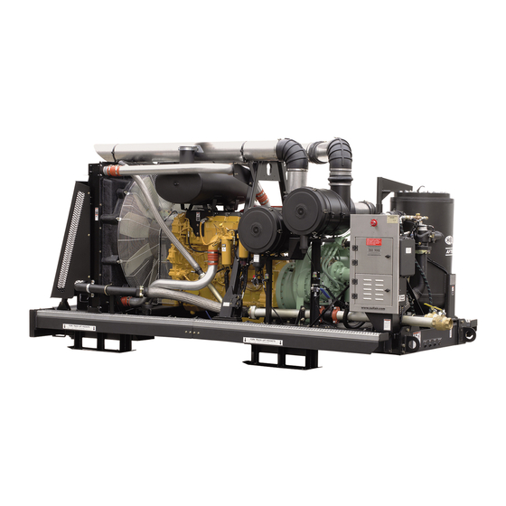
OPEN FRAME
AIR COMPRESSOR
900XH - 1350XH
and Aftercooled Models
CATERPILLAR
350 PSIG
OPERATOR'S
MANUAL AND
PARTS LIST
KEEP FOR
FUTURE
REFERENCE
Part Number
02250166-434
©Sullair Corporation
The information in this document is
correct at the time of printing for
Portable Compressor Serial Number
200601080007
and all subsequent Serial Numbers.
Advertisement
Table of Contents
Troubleshooting

Related Manuals for Sullair 900XH


Summary of Contents for Sullair 900XH
-
Page 1: Air Compressor
OPEN FRAME AIR COMPRESSOR 900XH - 1350XH and Aftercooled Models 350 PSIG CATERPILLAR OPERATOR’S MANUAL AND PARTS LIST KEEP FOR FUTURE REFERENCE Part Number 02250166-434 ©Sullair Corporation The information in this document is correct at the time of printing for... - Page 2 AIR CARE SEMINAR TRAINING Sullair Air Care Seminars are courses that provide hands-on instruction in the proper operation, maintenance and service of Sullair equipment. Individual seminars on Portable compressors are presented at regular intervals throughout the year at a dedi- cated training facility at the Sullair corporate headquarters in Michigan City, Indiana.
-
Page 3: Table Of Contents
1.9 LIFTING 1.10 ENTRAPMENT 1.11 JUMP STARTING Section 2 DESCRIPTION 2.1 INTRODUCTION 2.2 DESCRIPTION OF COMPONENTS 2.3 SULLAIR COMPRESSOR UNIT, FUNCTIONAL DESCRIPTION 2.4 COMPRESSOR COOLING AND LUBRICATION SYSTEM, FUNCTIONAL DESCRIPTION 2.5 COMPRESSOR DISCHARGE SYSTEM, FUNCTIONAL DESCRIPTION 2.6 CAPACITY CONTROL SYSTEM, FUNCTIONAL DESCRIPTION 2.7 AIR INLET SYSTEM, FUNCTIONAL DESCRIPTION... - Page 4 TABLE OF CONTENTS Section 3 SPECIFICATIONS 3.1 SPECIFICATIONS 3.2 LUBRICATION GUIDE - COMPRESSOR 3.3 APPLICATION GUIDE 3.4 LUBRICATION GUIDE - ENGINE Section 4 OPERATION 4.1 GENERAL 4.2 PURPOSE OF CONTROLS 4.3 INITIAL START-UP PROCEDURE 4.4 SUBSEQUENT START-UP PROCEDURE 4.5 SHUTDOWN PROCEDURE Section 5 MAINTENANCE 5.1 GENERAL...
- Page 5 7.10 SPEED CONTROL CYLINDER AND PARTS - ALL MODELS 7.11 AIR CONTROL MANIFOLD ASSEMBLY - ALL MODELS 7.12A INLET VALVE AND PARTS (6.5”) - 900XH 7.12B INLET VALVE AND PARTS (8”) - 1150XH AND 1350XH 7.13A INLET VALVE PARTS - 6.5” - 900XH 7.13B INLET VALVE PARTS - 8”...
-
Page 7: General
Section 1 SAFETY 1.1 GENERAL NOTE (cont.) Sullair Corporation designs and manufactures all of its products so they can be operated safely. tow vehicle, as the vehicle may not However, the responsibility for safe operation rests brake safely with excess weight. See with those who use and maintain these products. -
Page 8: Towing
Section 1 SAFETY lized, chain adjustment, brake and/or electrical and reinsert the pin. Make sure the jack is secured interconnections) DO NOT interfere with or restrict in place prior to towing. motion of any part of the compressor, including its 9. - Page 9 Section 1 SAFETY b. All other models: 55 MPH (88KMPH). vehicle, then hook chains to bail on drawbar or wrap chains around the drawbar and hook them to them- 3. Remember that the portable air compressor may selves to keep chains off the ground which might approach or exceed the weight of the towing vehi- accelerate rusting.
-
Page 10: Pressure Release
Section 1 SAFETY drawbar or if hinged, to raise it to the upright posi- running and is not pressurized. Shut down the tion, by hand, if the weight is more than you can compressor and bleed the sump (receiver) to zero safely handle. - Page 11 Section 1 SAFETY to refueling. antifreeze compound, prior to attempting weld repairs in any place other than the fuel system. DO B. Clean up spills of fuel, fluid, battery electrolyte or NOT weld on or near the fuel system. coolant immediately if such spills occur. K.
-
Page 12: Moving Parts
Section 1 SAFETY moving parts. 1.7 TOXIC AND IRRITATING SUBSTANCES A. DO NOT use air from this compressor for respi- B. DO NOT attempt to operate the compressor with ration (breathing) except in full compliance with the fan or other guards removed. OSHA Standards 29 CFR 1920 and any other C. -
Page 13: Electrical Shock
Section 1 SAFETY antifreeze compound enters the eyes or if fumes allowance for weight of snow, ice, mud or stored irritate the eyes, they should be washed with large tools and equipment. If your are unsure of the quantities of clean water for 15 minutes. A physi- weight, then weigh compressor before lifting. - Page 14 Section 1 SAFETY E. Check fluid level. If low, bring fluid to proper level ed battery. before attempting to jump start (not applicable to P. Connect the other end of the same jumper cable maintenance-free batteries). to the positive (POS) (+) terminal of the starter F.
-
Page 15: Introduction
Sullair Corporation Service Department. required of the working parts within the compressor 2.2 DESCRIPTION OF COMPONENTS unit. Refer to Figure 2-1. The components and assem- Figure 2-1 Sullair Rotary Screw Open Frame Air Compressor - Typical Main Component Locations... -
Page 16: Sullair Compressor Unit, Functional Description
Section 2 DESCRIPTION blies of the Sullair 900XH-1350XH Open Frame Air the stator and also between the rotors them- Compressors models are clearly shown. The pack- selves. age includes a compressor unit, diesel engine, 3. Acts as a lubricating film between the rotors... -
Page 17: Compressor Discharge System, Functional Description
Refer to Figures 2-2, 2-3A or 2-3B. The Sullair com- ings of the compressor unit. The filter has a replace- pressor unit discharges compressed air/fluid mix- able element and a built-in bypass valve which ture into the sump. - Page 18 Section 2 DESCRIPTION Figure 2-3A Control System - 900XH, 1150XH and 1350XH Models...
- Page 19 Section 2 DESCRIPTION Figure 2-3B Control System - Aftercooled Models...
-
Page 20: Capacity Control System, Functional Description
Section 2 DESCRIPTION fluid separate and fall to the bottom of the sump. 2.6 CAPACITY CONTROL SYSTEM, FUNCTIONAL The fractional percentage of fluid remaining in the DESCRIPTION compressed air collects on the surface of the final Refer to Figure 2-3A or 2-3B. -
Page 21: Air Inlet System, Functional Description
Section 2 DESCRIPTION Figure 2-4 Control System Diagram 02250077-331R03 to the inlet valve causing the check spring in the Section 5 for Air Filter Maintenance Procedures. inlet valve to close the air inlet valve. This sends a These indicators should be checked daily, after pressure signal to the blowdown valve causing it to start-up under normal conditions. - Page 22 Section 2 DESCRIPTION Figure 2-5A EMS (Engine Monitoring System) Unit • engine speed: • intake manifold temperature: L Air • fuel temperature: • engine oil pressure: FUEL GA -1 • accessory pressure (not used): • coolant temperature: ACCR P GA -2 •...
- Page 23 Section 2 DESCRIPTION Figure 2-5B Instrument Panel Group Description). • The air pressure gauge continually moni- tors the sump pressure at various load and/or unload conditions. • The voltmeter monitors the condition of the batteries and the charging circuit. The nor- mal reading is 24 to 28 volts.
-
Page 24: Engine Control Module, Functional
Section 2 DESCRIPTION Table 1 - Engine to Warning Lamp Actions CID-FMI Description Warning Lamp Time to Shutdown Start/Restart Time 100 - 01 Low Fluid Pressure Warning 100 - 11 Very Low Fluid Pressure Flashing 30 Seconds 18 Seconds High Inlet Manifold Air 105 - 00 Temperature Warning Very High Inlet Manifold Air... -
Page 25: Electrical System, Functional Description
Section 2 DESCRIPTION power-up to test the lamp operation (self test). Diagnostic Codes. The lamp will begin to flash (ON, then OFF, ON...) 2.10 ELECTRICAL SYSTEM, FUNCTIONAL after the five second self test. The sequence of DESCRIPTION flashes represent the Flash Code diagnostic mes- Refer to Figure 2-7. -
Page 26: Aftercooler Air System, System, Functional Description
After-cooler system should not be temperature.Two discharge valves are provided on operated in ambient conditions below all 900XH -1350XH compressor models. 32º F (0ºC). If it is necessary to oper- valve is labeled standard air and one valve is ate in these conditions, Sullair can labeled aftercooled air. - Page 27 (I) The engine will shut down if both speed/timing sensors are lost. (II) Fuel injection will not occur and the engine will not start. NOTE: Sullair engines are programmed to shut down. CID = Component Identifier SPN = Suspect Paramater Number FMI = Failure Mode Identifier Continued...
- Page 28 Section 2 DESCRIPTION Table 2 - Possible Performance of Active Diagnostic Codes (continued) Reduced Flash CID-FMI SPN-FMI Engine Engine Description of Code Engine Code Code Code Misfires Power Shutdown Speed J1939 Data Link communications 247-09 639-09 High Engine Coolant Temperature Derate 0110-16 High Engine Coolant Temperature Shutdown 0110-00...
- Page 29 Section 2 DESCRIPTION Figure 2-7 Wiring Diagram 02250145-161R01...
- Page 30 NOTES...
-
Page 31: Specifications
Section 3 SPECIFICATIONS 3.1 SPECIFICATIONS Length Width Height Weight (wet) (I) Model Series 900XH, 1150XH & 1350XH 177.1 44498 87.5 2222 2261 12500 5670 OPEN FRAME (I) Aftercooled add 500 lbs / 227 kg COMPRESSOR : 900XH MODELS 1150XH MODELS... -
Page 32: Lubrication Guide - Compressor
Mobil Rarus SHC 1024 1000 -20 to 100 (-29 to 38) (I) Sullair part numbers for multi-viscosity lubricants are 250030-757 for 5 gallon / 20 liter container, and 250030-758 for 55 gallon / 208 liter container. 3.3 APPLICATION GUIDE When ambient conditions exceed those noted or if Refer to Figure 3-1. - Page 33 Section 3 SPECIFICATIONS Figure 3-2 Identification - Compressor Assembly 02250135-977R03...
- Page 34 NOTES...
-
Page 35: General
OPERATION 4.1 GENERAL will call for service or indicate the beginning of a While Sullair has built into this compressor a com- malfunction. Before starting your Sullair compres- prehensive array of controls and indicators to sor, read this section thoroughly and familiarize... -
Page 36: Initial Start-Up Procedure
Section 4 OPERATION 4.2 PURPOSE OF CONTROLS (CONTINUED) CONTROL OR INDICATOR PURPOSE MINIMUM PRESSURE / CHECK VALVE Maintains a minimum of 200 psig (13.8 bar) in the compres- sor sump. This valve restricts receiver air discharge from receiver/sump when pressure falls to 200 psig (13.8 bar). Also prevents back flow into the sump during unload conditions and after shutdown. -
Page 37: Shutdown Procedure
Section 5 MAINTENANCE 4. Below 40°F (4°C) use starting aid (per instruc- 4.5 SHUTDOWN PROCEDURE tions printed on starting aid device). To shut the compressor down, close the service valves and turn the start/run control valve to the 5. Turn engine switch to the “ignition” position. “start”... - Page 38 NOTES...
-
Page 39: General
5.7 MAINTENANCE EVERY 500 HOURS After a routine start has been made, observe the When using Sullair AWF, replace the fluid filter ele- instrument panel gauges and be sure they monitor ment and change compressor fluid. (See mainte- the correct readings for their particular phase of nance procedures in Section 5.10). -
Page 40: Parts Replacement And Adjustment Procedures
Section 5 MAINTENANCE 1. Clean the return line orifice and strainer. clean. 5.9 PARTS REPLACEMENT AND ADJUSTMENT 6. Apply a light film of fluid to o-ring and place it in PROCEDURES its proper position. COMPRESSOR FLUID CHANGE PROCEDURE 7. Place new, clean element in housing, centering it Warm-up the compressor for 5 to 10 minutes to on location in the head. - Page 41 Section 5 MAINTENANCE Figure 5-2 Air Filter (P/N 02250049-036 [engine] and P/N 02250053-402 [compressor]) *Primary Replacement Filter Element P/N 02250051-238 **Secondary Replacement Filter Element P/N 02250051-239 ELEMENT REMOVAL ELEMENT INSPECTION 1. Clean the exterior of the air filter housing. 1. Place a bright light inside the element to inspect for damage or leak holes.
-
Page 42: Control System Adjustment
Section 5 MAINTENANCE Figure 5-3 Control System Components CONTROL SYSTEM ADJUSTMENT 2. Open service valve slightly and turn the warm-up Refer to Figure 5-3, or control schematic (Figure 2- valve to "run" position. Slowly close the service 3). Prior to adjusting the control system, it is neces- valve, watching the pressure gauge to insure the sary to determine the desired operating pressure unload pressure does not exceed 350 psig (24.1... -
Page 43: Separator Element Replacement
Before installing, lubricate both sides of the gasket (i.e. Silglyde). Reinstall the tank lid. lid, Sullair has provided a 1"-8 nut to Install the capscrews finger tight, then gradually the top lid so it can be removed by a 1"- tighten in a crisscross pattern in 4 to 5 steps. -
Page 44: Troubleshooting Guide
Section 5 MAINTENANCE 5.11 TROUBLESHOOTING GUIDE SYMPTOM PROBABLE CAUSE REMEDY COMPRESSOR WILL NOT No Fuel Check fuel level and add fuel if necessary. START Plugged Fuel Filter Replace the element. Low Battery Voltage Check electrolyte level and add distilled water and recharge if necessary. - Page 45 Section 5 MAINTENANCE 5.11 TROUBLESHOOTING GUIDE SYMPTOM PROBABLE CAUSE REMEDY MPROPER UNLOADING Running Blowdown Valve Pressure Readjust. WITH AN EXCESSIVE Regulating Valve Set Too High PRESSURE BUILD-UP Leak in Control System Causing Check control lines. CAUSING PRESSURE Loss of Pressure Signal RELIEF VALVE TO Worn seals in inlet valve.
- Page 46 Section 5 MAINTENANCE 5.11 TROUBLESHOOTING GUIDE (CONTINUED) SYMPTOM PROBABLE CAUSE REMEDY ENGINE OVERHEATING Dirty Aftercooler Clean thoroughly. (CONTINUED) Low Fluid Level Refill. Faulty Water Pump Change pump. Plugged Radiator Clean and flush thoroughly. Defective Engine Thermostat Replace engine thermostat. SHUTDOWN PANEL Faulty Switch Indicated by Light Replace the switch.
-
Page 47: Noise Emissions Warranty
NOISE CONTROL 6.1 NOISE EMISSIONS WARRANTY dered inoperative by any person. Sullair Corporation warrants to the ultimate pur- Among those acts included in the prohibition chaser and each subsequent purchaser that this air against tampering are the acts listed below: compressor was designed, built and equipped to 1. - Page 48 Section 6 NOISE CONTROL 2. ANNUAL AIR FILTER(S) AND AIR INLET SYSTEM INSPECTION In addition to the instructions in the Maintenance section of the Operator’s Manual, the air filter(s) and entire air inlet system should be inspected at least annually, to make sure all parts are securely mounted, that all joints and connections are tight, that there are no other leaks in the system, and that the filter element(s) are intact.
- Page 49 Section 6 NOISE CONTROL 4. ANNUAL FRAME, CANOPY, AND PARTS INSPECTION At least annually inspect frame, canopy and parts, for security of attachment. Make sure there are not any missing or deformed members, including all hinged doors, covers and their fastening devices. DO NOT oper- ate compressor with defective frame, canopy and parts.
- Page 50 Section 6 NOISE CONTROL 6. ANNUAL INSPECTIONS FOR PROPER OPERATION OF ALL SYSTEMS In addition to other instructions in the Operator’s Manual, at least annually, operate compressor and inspect to make sure all systems are operating properly and that engine runs at rated speed and pressure. DO NOT operate malfunctioning or improperly adjusted compressor.
-
Page 51: Procedure For Ordering Parts
ILLUSTRATIONS AND PARTS 7.1 PROCEDURE FOR ORDERING PARTS Parts should be ordered from the nearest Sullair Representative or the Representative from whom the com- pressor was purchased. If for any reason parts cannot be obtained in this manner, contact the factory directly at the addresses, websites, telephone or fax numbers below. - Page 52 Section 7 ILLUSTRATIONS AND PARTS 7.2 SPARE PARTS LIST LIST DESCRIPTION ORDER REFERENCE KIT NUMBER ELEMENTS replacement element for air filter 02250049-036 (primary) 02250051-238 replacement element for air filter 02250049-036 (secondary) 02250051-239 replacement element for air filter 02250053-402 (primary) 02250051-238 replacement element for air filter 02250053-402 (secondary) 02250051-239 replacement element for separator 409805-007 (900-1150)
- Page 53 Section 7 ILLUSTRATIONS AND PARTS 7.2 SPARE PARTS LIST (CONTINUED) LIST DESCRIPTION ORDER REFERENCE KIT NUMBER KITS (continued) replacement kit for moisture separator 02250058-442 02250058-441 replacement handle for 3-way valve 044205 Consult Factory LUBRICATION lubricant, multi-vis (55 gallons/208 liters) 250030-758 lubricant, multi-vis (5 gallons/20 liters) 250030-757 MICELLANEOUS...
-
Page 54: Engine And Compressor Mounting
Section 7 ILLUSTRATIONS AND PARTS 7.3 ENGINE AND COMPRESSOR MOUNTING 02250127-622R08... - Page 55 2.5 npt x 2.5 4bsf disch (II) 02250081-044 panel, heat shield 02250117-891 belt, set cat 4n-6423 (.57:1) 02250121-879 tube, radiator upper 900xh-1900 02250128-894 spacer, fan cat c15 49.63” fan 02250133-590 clamp, hose 3” 040343 clamp, hose 13/16” to 1-1/2”...
- Page 56 Section 7 ILLUSTRATIONS AND PARTS 7.3 ENGINE AND COMPRESSOR MOUNTING 02250127-622R08...
-
Page 57: Check Valve / Orifice
(VII) There is an exchange program whereby a remanufactured compressor unit can be obtained from Sullair distributors or the factory at less cost than the owner could repair the unit. For information regarding the unit exchange program, contact your nearest Sullair representative or the Sullair Corporation. -
Page 58: Air Inlet System - All Models
Section 7 ILLUSTRATIONS AND PARTS 7.4 AIR INLET SYSTEM - ALL MODELS 02250136-060R02... - Page 59 238, and secondary replacement element no. 02250051-239. (III) For complete breakdown of 6.5” inlet valve assembly, refer to Section 7.13A Inlet Valve Parts - 6.5” 900XH. For complete breakdown of 8” inlet valve assembly, refer to Section 7.13B Inlet Valve Parts - 8” - 1150XH-1350XH.
- Page 60 Section 7 ILLUSTRATIONS AND PARTS 7.4 AIR INLET SYSTEM - ALL MODELS 02250136-060R02...
- Page 61 Section 7 ILLUSTRATIONS AND PARTS 7.4 AIR INLET SYSTEM - ALL MODELS (CONTINUED) part number description number quantity clamp, hose 8" 043598 tube, alum air inlet 6"od x 20"lg 233298 elbow, rubber 90deg red. 8 x 7" 245796 tube, alum air inlet 8"od x 12"lg 250006-651 elbow, 90d 1/4"...
-
Page 62: Exhaust System - All Models
Section 7 ILLUSTRATIONS AND PARTS 7.5 EXHAUST SYSTEM - ALL MODELS 02250136-062R02... - Page 63 02250135-706 enclosure, instrument panel 02250135-709 cover, instrument panel backing 02250135-710 supt, instr box 900 xh open frame 02250137-188 supt, 900xh open frame 02250137-189 supt, baffle 1150xha tier ii 02250140-520 grommet, rubber 040125 clamp, seal 5” 241260...
- Page 64 Section 7 ILLUSTRATIONS AND PARTS 7.6A ENGINE RADIATOR AND FLUID COOLING SYSTEM 02250127-635R02...
- Page 65 Models. (II) For additional information pertaining to receiver & parts sub-assembly no. 02250127-668, consult Section 7.15A, Receiver and Parts - 900XH & 1150XH Standard and Aftercooled. (III) For maintenance on filter assembly no. 250031-849, order replacement element kit no. 250031-850.
- Page 66 Section 7 ILLUSTRATIONS AND PARTS 7.6A ENGINE RADIATOR AND FLUID COOLING SYSTEM 02250127-635R02...
- Page 67 Section 7 ILLUSTRATIONS AND PARTS 7.6A ENGINE RADIATOR AND FLUID COOLING SYSTEM (CONTINUED) part number description number quantity screw, hex ser washer 5/16-18 x 3/4 829705-075 screw, hex ser washer 5/16-18 x 1 829705-100 washer, pl-b reg unfin 5/16 837205-071 washer, pl-b reg unfin 3/4 837212-112 washer, spr lock 5/16...
-
Page 68: Aftercooled
Section 7 ILLUSTRATIONS AND PARTS 7.6B ENGINE RADIATOR AND FLUID COOLING SYSTEM - AFTERCOOLED 02250150-195R01... -
Page 69: Aftercooled
2” pipe 02250148-710 support, for 02250148-710 02250148-711 sub assembly, cooler air/oil assy 900xh 02250127-628 •sub-assembly, clr/air/oil vert flo lvrs 900xh (III) 02250150-201 flange, kit sae splt 2” 250016-435 valve, oil stop 2” sae code 61 (IV) 250041-069... -
Page 70: Aftercooled
Section 7 ILLUSTRATIONS AND PARTS 7.6B ENGINE RADIATOR AND FLUID COOLING SYSTEM - AFTERCOOLED 02250150-195R01... -
Page 71: Aftercooled
Section 7 ILLUSTRATIONS AND PARTS 7.6B ENGINE RADIATOR AND FLUID COOLING SYSTEM - AFTERCOOLED (CONTINUED) part number description number quantity o-ring, viton 2 1/4 x 1/8” 826502-228 capscrew, hex gr5 5/16-18 x 3/4 829105-075 capscrew, hex gr5 1/2-13 x 1 1/4 829108-125 capscrew, hex gr5 1/2-13 x 1 1/2 829108-150... -
Page 72: Engine Radiator Assembly - All Models
Section 7 ILLUSTRATIONS AND PARTS 7.7 ENGINE RADIATOR ASSEMBLY - ALL MODELS 02250127-633R02... - Page 73 013978 2 ft. hose, rad lower cat 3406 02250048-926 venturi, 50.50” special 02250092-488 baffle, rad ss 900xh tier ii 02250127-631 baffle, rad cs 900xh tier ii 02250127-632 radiator, 900xh-1900 02250128-893 baffle, canopy cs 900xh ac 02250131-791...
-
Page 74: Aftercooler Mounting - All Models
Section 7 ILLUSTRATIONS AND PARTS 7.8 AFTERCOOLER MOUNTING - ALL MODELS 02250150-135R03... - Page 75 1200/1500 02250108-474 cooler, air cat 3406e tier ii 02250124-822 cooler, oil ca 3406 tier ii 900xh 02250126-734 cooler, air vert flow 500 psig 02250150-059 support, brk vert flow clr 900xh-1150xh 02250150-088 support, vertical flow clr 900xh-1150xh...
-
Page 76: Control System Hose Routing - All Models
Section 7 ILLUSTRATIONS AND PARTS 7.9 CONTROL SYSTEM HOSE ROUTING - ALL MODELS 02250133-812R05... - Page 77 Section 7 ILLUSTRATIONS AND PARTS 7.9 CONTROL SYSTEM HOSE ROUTING - ALL MODELS part number description number quantity hose, mp 5/16 x 98" lg 37deg st 02250073-546 hose, mp 5/16 x 54" lg 37deg st 02250083-838 hose, mp 5/16 x 17 02250110-099 hose, mp 5/16 x 40"...
- Page 78 Section 7 ILLUSTRATIONS AND PARTS 7.10 SPEED CONTROL CYLINDER AND PARTS - ALL MODELS 02250132-482R00...
-
Page 79: Speed Control Cylinder And Parts - All Models
Section 7 ILLUSTRATIONS AND PARTS 7.10 SPEED CONTROL CYLINDER AND PARTS - ALL MODELS part number description number quantity support, speed cyl mtg 3406e 02250085-277 cylinder, air dbl acting (I) 02250112-029 lever, speed control 1600h-1900 02250112-037 washer, sprlock hi clr 5/16” 02250112-561 rod end, spherical rh 5/16 040136... -
Page 80: Air Control Manifold Assembly - All Models
Section 7 ILLUSTRATIONS AND PARTS 7.11 AIR CONTROL MANIFOLD ASSEMBLY - ALL MODELS 02250132-419R04... - Page 81 Section 7 ILLUSTRATIONS AND PARTS 7.11 AIR CONTROL MANIFOLD ASSEMBLY - ALL MODELS part number description number quantity housing, air ctrl manifold 02250116-255 valve, check 1/2” cartridge type 02250116-869 hose, mp-5 11”lg 37deg svl str 02250118-270 orifice, .047 .25 fnpt x .25 mnpt 02250118-584 switch, pressure nc 15 psi 600 mp 02250129-848...
- Page 82 Section 7 ILLUSTRATIONS AND PARTS 7.12A INLET VALVE AND PARTS (6.5”) - 900XH 02250140-983R01...
- Page 83 Section 7 ILLUSTRATIONS AND PARTS 7.12A INLET VALVE AND PARTS (6.5”) - 900XH part number description number quantity adapter, inlet 8.5” to 6.5” 02250062-124 plug, sae 45 deg 5/16 1/2-20 02250109-209 hose, medium pressure 5/16 x 4.5”lg 37$s jic 02250110-100 orifice, .109 .25 fnpt x .25 mnpt...
-
Page 84: B Inlet Valve And Parts (8") - 1150Xh And 1350Xh
Section 7 ILLUSTRATIONS AND PARTS 7.12B INLET VALVE AND PARTS (8”) - 1150XH AND 1350XH 02250134-298R01... - Page 85 Section 7 ILLUSTRATIONS AND PARTS 7.12B INLET VALVE AND PARTS (8”) - 1150XH AND 1350XH part number description number quantity sub assembly, 8” inlet valve (I) (II) 02250045-626 plug, sae 45 deg 5/16 1/2-20 02250109-209 hose, medium pressure 5/16 x 4.5”lg 37° jic 02250110-100 orifice, .109 .25 fnpt x .25 mnpt 02250118-588...
-
Page 86: A Inlet Valve Parts - 6.5" - 900Xh
Section 7 ILLUSTRATIONS AND PARTS 7.13A INLET VALVE PARTS - 6.5” - 900XH 02250054-762R06... - Page 87 Section 7 ILLUSTRATIONS AND PARTS 7.13A INLET VALVE PARTS - 6.5” - 900XH part number description number quantity housing, body 6.5” inlet valve 02250054-750 plate, assy 6.5” inlet valve 02250054-754 cover, inter 6.50”valve 02250054-757 piston, 6.50 inlet valve 02250054-759 spring, compresion, 1.50 lbs 02250054-761 cover, assembly 6.50”...
-
Page 88: B Inlet Valve Parts - 8" - 1150Xh And 1350Xh
Section 7 ILLUSTRATIONS AND PARTS 7.13B INLET VALVE PARTS - 8” - 1150XH AND 1350XH 02250045-625R05... - Page 89 Section 7 ILLUSTRATIONS AND PARTS 7.13B INLET VALVE PARTS - 8” - 1150XH AND 1350XH part number description number quantity housing, body 8” inlet valve 250042-276 cover, assembly 8” inlet valve 02250048-491 plate, flow control 8” inlet valve 250042-297 cover, inter 8” inlet valve 250042-301 piston, 8”...
- Page 90 Section 7 ILLUSTRATIONS AND PARTS 7.14A DISCHARGE SYSTEM - 900XH AND 1150XH 02250127-667R10...
- Page 91 Section 7.18, Discharge / Check Valve Assembly. (II) For additional information pertaining to receiver and parts sub-assembly no. 02250127-668, refer to Section 7.15A Receiver and Parts - 900XH & 1150XH Standard and Aftercooled. PLEASE NOTE: WHEN ORDERING PARTS, INDICATE THE SERIAL NUMBER OF COMPRESSOR...
-
Page 92: Aftercooled
Section 7 ILLUSTRATIONS AND PARTS 7.14B DISCHARGE SYSTEM - 900XH-1150XH AFTERCOOLED 02250139-931R06... -
Page 93: Aftercooled
900xh ac (II) 02250131-654 adapter, 2” tube assy w/4-bolt flg 02250131-977 sub assembly, air control manifold 900xh tier ii (III) 02250132-421 sub assembly, speed control tier ii (IV) 02250132-481 pipe, assembly trap/svr vlv 900xh ac... - Page 94 Section 7 ILLUSTRATIONS AND PARTS 7.14B DISCHARGE SYSTEM - 900XH-1150XH AFTERCOOLED 02250139-931R06...
- Page 95 Section 7 ILLUSTRATIONS AND PARTS 7.14B DISCHARGE SYSTEM - 900XH-1150XH AFTERCOOLED (CONTINUED) part number description number quantity pipe, asy rec tnk/a-clr 1150/500 ac w/val 02250142-708 hose, asy 2” braided ss 48”lg 02250148-552 switch, temp-265f 54” los nc 045641 gasket, 2-1/2” flange...
- Page 96 Section 7 ILLUSTRATIONS AND PARTS 7.14C DISCHARGE SYSTEM - 1350XH AFTERCOOLED 02250148-288R01...
- Page 97 02250081-044 hose, medium pressure 5/16 x 54” lg 37deg st 02250083-838 valve, ball 2” fnpt w/o drain 02250086-337 hose, disch 2.5” st stl 900xh 02250092-744 flange, kit sae splt 2” - viton 02250099-415 flange, kit sae splt 2.5” - viton 02250099-416 adapter, 2”...
- Page 98 Section 7 ILLUSTRATIONS AND PARTS 7.14C DISCHARGE SYSTEM - 1350XH AFTERCOOLED 02250148-288R01...
- Page 99 Section 7 ILLUSTRATIONS AND PARTS 7.14C DISCHARGE SYSTEM - 1350XH AFTERCOOLED (CONTINUED) part number description number quantity nut, hex pltd 3/8-16 825106-337 nut, hex pltd 1/2-13 825208-448 nut, hex pltd 5/8-11 825210-559 capscrew, hex gr8 3/4-10 x 2 1/4 827912-225 capscrew, hex gr5 1/2-13 x 1 1/2 829108-150 capscrew, hex gr5 5/8-11 x 2 3/4...
-
Page 100: Standard And Aftercooled
Section 7 ILLUSTRATIONS AND PARTS 7.15A RECEIVER AND PARTS - 900XH & 1150XH STANDARD AND AFTERCOOLED 02250127-666R14... -
Page 101: Standard And Aftercooled
Section 7 ILLUSTRATIONS AND PARTS 7.15A RECEIVER AND PARTS - 900XH & 1150XH STANDARD AND AFTERCOOLED part number description number quantity cap, nut .50 x 37d flare 02250044-227 separator, moisture 425 psi @ 265deg (I) 02250058-442 valve, blwdwn n.c. 5.4:1 ratio (II) 02250069-820 receiver, air/oil vert. -
Page 102: Standard And Aftercooled
Section 7 ILLUSTRATIONS AND PARTS 7.15A RECEIVER AND PARTS - 900XH & 1150XH STANDARD AND AFTERCOOLED 02250127-666R14... -
Page 103: Standard And Aftercooled
Section 7 ILLUSTRATIONS AND PARTS 7.15A RECEIVER AND PARTS - 900XH & 1150XH STANDARD AND AFTERCOOLED (CONTINUED) part number description number quantity o-ring, viton 2 1/4 x 1/8” 826502-228 screw, hex ser washer 5/16-18 x 3/4 829705-075 washer, spr lock reg pltd 1/2... -
Page 104: Standard And Aftercooled
Section 7 ILLUSTRATIONS AND PARTS 7.15A RECEIVER AND PARTS - 900XH & 1150XH STANDARD AND AFTERCOOLED 02250127-666R14... -
Page 105: Standard And Aftercooled
Section 7 ILLUSTRATIONS AND PARTS 7.15A RECEIVER AND PARTS - 900XH & 1150XH STANDARD AND AFTERCOOLED (CONTINUED) part number description number quantity elbow, pipe 90 deg 1/2” 3000# plt 877900-020 elbow, pipe 90 deg 1” 3000# plt 877900-040 elbow, pipe 90 deg 1 1/2” 3000# plt 877900-060 flange, kit sae splt 2”... -
Page 106: And Aftercooled
Section 7 ILLUSTRATIONS AND PARTS 7.15B RECEIVER AND PARTS- 1350XH STANDARD AND AFTERCOOLED 02250148-287R02... -
Page 107: And Aftercooled
2” -vi ton 02250099-415 gskt, sep cover h i press (I) 02250116-862 plate, rece iver 425xh & 900xh 02250121-613 adpt, 2” tube assy w/4-bolt flg (II) 02250131-977 hose, mp 0.50 x 1-1/16 sae x 38” lg... -
Page 108: And Aftercooled
Section 7 ILLUSTRATIONS AND PARTS 7.15B RECEIVER AND PARTS- 1350XH STANDARD AND AFTERCOOLED 02250148-287R02... -
Page 109: And Aftercooled
Section 7 ILLUSTRATIONS AND PARTS 7.15B RECEIVER AND PARTS- 1350XH STANDARD AND AFTERCOOLED (CONTINUED) part number description number quantity sa, vlv min press/chk asm(2.5”) (VI) 02250164-871 plug, str tho 1 5/8-12 sae vit 250042-627 clamp, hose 5/8” 1.0. 408300-005 nut, hex pltd 3/4-10 825212-665 nut, hex f pltd 5/16-18 825305-283... -
Page 110: Water Separator Trap - Aftercooled Only
Section 7 ILLUSTRATIONS AND PARTS 7.16 WATER SEPARATOR TRAP - AFTERCOOLED ONLY 02250131-653R11... - Page 111 5/16 x 54”lg 37deg jic 90 02250077-839 separator, t type gas/liq 2” npt 02250131-542 trap, drain float type 1” npt 02250131-543 panel, separator assy 900xh ac 02250131-656 adapter, 2” tube assy w/4-bolt flg 02250131-977 orifice, .060 .50m x .50m 02250161-248 clamp, hose 1/2”...
- Page 112 Section 7 ILLUSTRATIONS AND PARTS 7.16 WATER SEPARATOR TRAP - AFTERCOOLED ONLY 02250131-653R11...
- Page 113 Section 7 ILLUSTRATIONS AND PARTS 7.16 WATER SEPARATOR TRAP - AFTERCOOLED ONLY (CONTINUED) part number description number quantity u-bolt, 1/2” x 6” pipe pltd 868308-600 nipple, pipe-hx pltd 3/8 x 3/8 868506-038 bushing, red hex pltd 1 x 1/2 868904-020 elbow, pipe 45 deg 2”...
-
Page 114: Discharge / Check Valve Assembly
Section 7 ILLUSTRATIONS AND PARTS 7.17 SUB-ASSEMBLY - HIGH PRESSURE FILTER / CHECK VALVE / ORIFICE 02250145-009R01 7.18 DISCHARGE / CHECK VALVE ASSEMBLY 02250049-879R04... - Page 115 Section 7 ILLUSTRATIONS AND PARTS 7.17 SUB-ASSEMBLY - HIGH PRESSURE FILTER / CHECK VALVE / ORIFICE part number description number quantity filter, assembly screen filter (I) 02250117-782 orifice, plug brass 1/8”npt x 3/32” 02250125-776 sightglass, orf block sae 02250126-129 valve, inline check (1/4”npt) dc 045244 elbow, 37fl 90m 1/4 x 1/4 860204-025...
- Page 116 Section 7 ILLUSTRATIONS AND PARTS 7.19 MINIMUM PRESSURE / CHECK VALVE 02250164-870R01...
-
Page 117: Minimum Pressure / Check Valve
Section 7 ILLUSTRATIONS AND PARTS 7.19 MINIMUM PRESSURE / CHECK VALVE part number description number quantity body assy, min/press valve 02250045-892 piston, min/pressure valve 02250045-893 spacer, min/press valve spring 02250045-894 cover. mpv lv dhh20 gi ma 224589 gasket, mp cover 224593 retainer, 2.94 x 0.31 spl 224594... -
Page 118: Fuel System And Parts - All Models
Section 7 ILLUSTRATIONS AND PARTS 7.20 FUEL SYSTEM AND PARTS - ALL MODELS 02250136-066R00... - Page 119 Section 7 ILLUSTRATIONS AND PARTS 7.20 FUEL SYSTEM AND PARTS - ALL MODELS part number description number quantity sender, fuel level 45” length 02250047-049 sw, liq level vert fuel 12v 02250047-335 tube, assy fuel pick-up 16000 02250049-998 conn, tube 3/8t x 3/8p special 02250051-257 valve, check fuel 1/2”...
-
Page 120: Electrical Parts - All Models
Section 7 ILLUSTRATIONS AND PARTS 7.21 ELECTRICAL PARTS - ALL MODELS 02250127-727R01... - Page 121 2/0 x 114” lg red 02250058-614 cable, batt 2/0 x 114” lg black 02250058-615 pnl, instr 900 xh tier ii (I) 02250127-728 harness, eng/compr 900xh tier ii 02250127-732 cable, ground #4 awg blk c 15 02250137-257 isolator, vibration l” od x 3/4” tall 040091 grommet, rubber 1”...
-
Page 122: Instrument Panel And Parts - All Models
Section 7 ILLUSTRATIONS AND PARTS 7.22 INSTRUMENT PANEL AND PARTS - ALL MODELS 02250127-728R03... - Page 123 02250087-547 circuit, board first out annun 02250087-558 lamp, miniature 24v-psb 02250094-725 decal, instrument panel 900xh tier ii 02250127-731 harness, instr panel 900xh tier ii 02250127-733 isolator, vibration 1”00 x 3/4”tall 040091 valve, 3-way ball (press sel)
- Page 124 Section 7 ILLUSTRATIONS AND PARTS 7.22 INSTRUMENT PANEL AND PARTS - ALL MODELS 02250127-728R03...
- Page 125 Section 7 ILLUSTRATIONS AND PARTS 7.22 INSTRUMENT PANEL AND PARTS - ALL MODELS (CONTINUED) part number description number quantity elbow, 37fl 90m 5/16 x 1/4 860205-025 elbow, 37fl 90f 5/16 x 1/4 860305-025 plug, pipe 1 /4” 3000 # stl plt 866900 -010 NOTE Engine mounting panel: decal and bazel are supplied with engine.
-
Page 126: Frame And Parts
Section 7 ILLUSTRATIONS AND PARTS 7.23 FRAME AND PARTS 02250136-503R02... - Page 127 02250044-410 panel, frame frt 4w option 1600q 02250050-086 support, air filter ss 02250135-591 support, air filter cs 02250135-592 bail, lifting 900xh through 1900 02250135-708 mount, utility feet 4” 02250136-210 support, muffler 900xh open frame 02250137-182 cover, batt 900xh open frame...
-
Page 128: Decal Group
Section 7 ILLUSTRATIONS AND PARTS 7.24 DECAL GROUP... - Page 129 Section 7 ILLUSTRATIONS AND PARTS 7.24 DECAL GROUP part number description number quantity decal, warning 100/1600 (I) 250028-258 sign, warning compressor fluid fill cap 049685 decal, warning pressurized clg sys 02250051-826 sign, warning sever belt drive 049964 sign, warning hot surfaces 407408 sign, warning sever fan port 049965...
- Page 130 Section 7 ILLUSTRATIONS AND PARTS 7.24 DECAL GROUP...
- Page 131 (all XHA models) 02250085-467 decal, aftercooled air (all XHA models) 02250085-468 decal, high / low 02250052-572 decal, aftercooler warning (all XHA models) 02250085-469 decal, Sullair AWF 250032-902 decal, water drain 040345 decal, receiver fluid fill level 1.75” 250023-655 decal, ISO 9001 02250057-624...
- Page 132 Section 7 ILLUSTRATIONS AND PARTS 7.24 DECAL GROUP...
- Page 133 02250086-562 decal, start - stop EMS functions 02250094-692 decal, rating 900XH - black 02250121-400 • decal, rating 900XH - white (not shown) 02250121-401 • decal, rating 1150XH - black (not shown) 02250138-298 • decal, rating 1150XH - white (not shown) 02250138-299 •...
- Page 134 Section 7 ILLUSTRATIONS AND PARTS 7.24 DECAL GROUP...
- Page 135 Section 7 ILLUSTRATIONS AND PARTS 7.24 DECAL GROUP (CONTINUED) part number description number quantity decal, panel 900xh tii 02250127-731 decal, Sullair logo 8.12” x 67” black 02250057-607 PLEASE NOTE: WHEN ORDERING PARTS, INDICATE THE SERIAL NUMBER OF COMPRESSOR...
-
Page 136: Decal Locations
Section 7 ILLUSTRATIONS AND PARTS 7.25 DECAL LOCATIONS 02250136-067R03... - Page 137 02250094-692 npl, sullair serial no. 1850-8f 02250108-078 decal, cat diesel power 02250109-529 decal, lead warning proposition 65 02250118-638 decal, sullair 7.63 x 45.75 white 02250121-332 decal, 900xh sullair decal, wire-diagram cat c15 02250127-584 decal, diesel fuel 040248 decal, water drain...
- Page 138 Section 7 ILLUSTRATIONS AND PARTS 7.25 DECAL LOCATIONS 02250136-067R03...
- Page 139 250023-655 decal, rated 1800 idle 1400 rpm 250023-695 decal, warning group 250028-258 decal, sullair awf 250032-902 decal, hot surfaces 407408 rivet, pop 1/8 x 3/8 843102-038 DECALS NOT SHOWN ON DRAWING PART NO.
- Page 140 NOTES...
- Page 142 WORLDWIDE SALES AND SERVICE SULLAIR ASIA, LTD. CHAMPION COMPRESSORS, Sullair Road, No. 1 LTD. Chiwan, Shekou Princes Highway Shenzhen, Guangdong PRV. Hallam, Victoria 3803 PRC POST CODE 518068 Australia : 755-6851686 : 61-3-9796-4000 Fax: 755-6853473 Fax: 61-3-9703-8053 www.sullair-asia.com www.championcompressors.com.au/ SULLAIR EUROPE, S.A.
Need help?
Do you have a question about the 900XH and is the answer not in the manual?
Questions and answers