
Related Manuals for CAME ZLB24SA


Summary of Contents for CAME ZLB24SA
- Page 1 Control panel for 24 V brushless gearmotors FA01894-EN ZLB24SA ZLB24SR INSTALLATION MANUAL English...
- Page 2 fi nal installation to comply with the Machinery Directive (2006/42/ EC) and with the reference harmonised technical standards are specifi ed in the general CAME product catalogue or on the website www.came.com. • Check that the temperature ranges given are suitable for the installation site. • Make sure that no direct jets of water can wet the product at the installation site (sprinklers, water cleaners, etc.).
- Page 3 fi nal machinery. • The product, in its original packaging supplied by the manufacturer, must only be transported in a closed environment (railway carriage, containers, closed vehicles). • If the product malfunctions, stop using it and contact customer services at https://www.came.com/global/en/contact-us or via the telephone number on the website.
- Page 4 UNI EN ISO 14001 standard to ensure that the environment is respected and safeguarded. Please continue safeguarding the environment. At CAME we consider it one of the fundamentals of our operating and market strategies. Simply follow these brief disposal guidelines: DISPOSING OF THE PACKAGING The packaging materials (cardboard, plastic, etc.) can be disposed of easily as solid urban waste, separated for recycling.
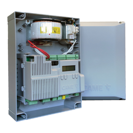
- Page 5 Description 801QA-0090 ZLB24SA - Multifunction control panel, with 230 VAC power supply, for FROG-X 24 V brushless gearmotors, with graphic programming display and signalling, safety device self-diagnostics, adaptive speed and torque technology, BUS CXN, 4 safety inputs and memory space for up to 1000 users.
- Page 6 Fuse table MODELS ZLB24SA ZLB24SR Line fuse 3.15 A F 6.3 A F Control-board fuse 1.6 A T 1.6 A T Accessory fuse 1.6 A F 1.6 A F Motor fuse 15 A T 15 A T...
- Page 7 Terminal board for connecting the gearmotor Terminal board for B1-B2 output Motor fuse Memory Roll card connector Accessories fuse Connector for CAME KEY Control board fuse Display Terminal board for connecting the signalling devices Programming buttons Terminal board for power supply to the control board...
- Page 8 Optional accessories RGSM001 module (806SA-0010) SMA module (009SMA) Use two emergency 12V 7Ah batteries.
- Page 9 Size...
- Page 10 Cable types and minimum thicknesses * no. = see product assembly instructions Warning: the cable cross-section is indicative and varies according to the motor power and cable length. Cable length (m) up to 20 from 20 to 30 Power supply 230 V AC 3G x 1.5 mm²...
- Page 11 INSTALLATION Preparing the control panel...
- Page 12 Fastening the control panel DIN rail Standard...
- Page 13 ELECTRICAL CONNECTIONS Preparing the electrical cables Connect all wires and cables in compliance with the law. Use cable glands to connect the devices to the control panel. One of these must be used exclusively for the power supply cable. Power supply Connecting to the mains (230/120 V AC - 50/60 Hz) F - Line fuse N - Neutral...
- Page 14 For subsequent connections, reposition the control board and remove the board protection. Power supply output for accessories Electric lock or electromagnets 12 V AC/DC - max 15 W. 10 11 E E3 5...
- Page 15 Power (W) Auxiliary contact B1 - B2 24 (24V AC/DC) BUS CXN 15 DC Do not connect anything other than CAME BUS accessories. FROG X gearmotors (801MI-0020) Connecting gearmotor pair M1 =Gearmotor delayed while opening M2 =Gearmotor delayed while closing...
- Page 16 Connecting a single gearmotor Red wire Grey wire Black wire...
- Page 17 Devices with BUS CXN system The CXN CAME system is a two-wire non-polarised communication BUS which allows you to connect up all compatible CAME devices. Connection to the BUS can be in a chain, star or mixed formation. Once the system has been wired, and after having set the address on each device, the function of each accessory can be confi...
- Page 18 Maximum number of devices that can be connected, by type Type of device Maximum number of devices per type Selectors Photocell pairs Interfaces Flashing beacons BUS CXN device consumption Scan the QR code to access an interactive table showing consumption data, and calculate the maximum number of BUS devices you can connect to the control panel.
- Page 19 Command and control devices STOP button (NC contact) Stop the gate and exclude automatic closing. Use a control device to resume movement. When the contact is being used, it must be activated during programming. See function [Total stop]. Control device (NO contact) Open command When the [Hold-to-run] function is active, a control device must be set to OPEN.
- Page 20 Signalling devices Flashing beacon It fl ashes when the operator opens and closes. Additional light It increases the light in the manoeuvring area. See [Additional light] function. Operator status warning light It notifi es the user of the operator status. See function [Passage-open warning light].
- Page 21 Safety devices During programming, confi gure the type of action that must be performed by the device connected to the input. Connect the safety devices to the CX and/or CY and/or CZ and/or CK inputs. If used, the contacts C1 CX CY CZ CK must be confi gured during programming. For systems with multiple pairs of photocells, please see the manual for the relevant accessory.
- Page 22 DXR - DLX photocells DXR - DLX photocells Standard connection Connection with safety test See [Safety devices test] function. 10 TS 2 CX CY CZ CK 10 11 E E3 5 10 TS 2 CX CY CZ CK 10 11 E E3 5 10 11 OUT 10 11 OUT 10 11 SY...
- Page 23 PROGRAMMING Programming button functions ESC button The ESC button is used to perform the operations described below. Exit the menu Delete the changes Go back to the previous screen Stop the operator < > buttons The <> buttons are used to perform the operations described below. Navigate the menu Increase or decrease values ENTER button...
- Page 24 Diagrams showing leaf speed, slowdown and approach points Closing limit-switch Opening speed Opening limit-switch Closing speed Opening slowdown point Opening slowdown speed Closing slowdown point Closing slowdown speed Opening approach point Approach speed (fi xed) Closing approach point Invert-motion zone in case of obstructions Stop-motion zone in case of obstructions Graph showing speed curves during movement, slowdown and approach.
- Page 25 Without using slowdown space (slowdown space = 0) Opening or closing speed Approach speed (fi xed) Obstruction travel sensitivity Opening or closing limit-switch Opening or closing approach point Functions menu Menu layout Some options only show on the display if certain conditions are met. For more information, please see the information for the individual functions.
- Page 26 Gate travel settings Opening speed Closing speed Travel AST control Part. open point Op. approach point Cl. approach point Opening slowdown point Closing slowdown point Opening slowdown speed Closing slowdown speed Slowdown AST control Impact test Confi gure M1 Opening speed Closing speed Op.
-
Page 27: Table Of Contents
Wired safety devices Total stop CX input CY input CZ input CK input Safety devices test RIO safety devices RIO ED T1 RIO ED T2 RIO PH T1 RIO PH T2 BUS Devices BUS Photocell 1 Photocell BUS 2 Photocell BUS 3 Photocell BUS 4 Photocell BUS 5 Photocell BUS 6... - Page 28 BUS 6 key selector Key to the right Key to the left BUS 7 key selector Key to the right Key to the left I/O module 1 input I1 input I2 Light output Relay output I/O module 2 input I1 input I2 Light output Relay output...
- Page 29 Times Automatic close Automatic partial close M1 open delay M2 close delay Manage lights Passage-open warning light Light E3 Courtesy time Pre-fl ashing time RSE communication CRP address RSE speed External memory Save data Read data Parameter reset Guided procedure (Wizard) Manage users New user Remove user...
- Page 30 Timer management Show clock Set the clock Automatic DST Time format Create new timer Open Start time End time Days of the week Partial opening Start time End time Days of the week B1-B2 output Start time End time Days of the week BUS 1 module relay Start time End time...
- Page 31 List of functions Number of motors Set the number of motors that control the gate. Confi guration> Number of motors M1+M2 (Default) Motor settings Opening direction Set the gate opening direction. By selecting an opening direction for M2, M1 is automatically set to the opposite direction. Confi...
- Page 32 Leaf weight Set the weight of leaves M1 and M2. Confi guration> Leaf weight Gate-leaf length 4 m Motor settings Maximum = 400 kg (Default) 50 kg to 400 kg (increments of 50 kg) Gate-leaf length 3.5 m Maximum = 500 kg (Default) 50 kg to 500 kg (increments of 50 kg) Gate-leaf length 3 m Maximum = 700 kg (Default)
- Page 33 Travel AST control Adjust the obstruction detection sensitivity during the gate travel in percentage terms. Confi guration> Travel AST control Deactivated (Default) Gate travel settings Maximum thrust and low obstruction sensitivity. Minimum Average Maximum* Minimum thrust and high obstruction sensitivity. Customised Customised closing Customised opening...
- Page 34 Closing slowdown point Set the percentage of the total travel to be used for the M1 and M2 closing slowdown. If the value set for M1 is diff erent to the value set for M2, only the value for M2 is shown here. Confi...
- Page 35 Impact test Activate/deactivate test mode for impact tests. With the function on, the operator does not signal errors connected to obstacle detection after more than one consecutive impact. Test mode is deactivated automatically after 1 hour. With the function on, the display shows the icon.
-
Page 36: Safety Devices Test
CX input , CY input , CZ input , CK input Associate a function with the input CX CY CZ CK Confi guration> CX input Deactivated (Default) Wired safety devices CY input C1 = Reopen while closing (photocells) CZ input C2 = Reclose while opening (photocells) CK input C3 = Partial stop Only with [Automatic close] activated. -
Page 37: Rio Safety Devices
RIO ED T1 and RIO ED T2 Associate one of the available functions with a wireless safety device. The function only appears if the RIO CONN interface board is present. Confi guration> RIO ED T1 Deactivated (Default) RIO safety devices RIO ED T2 P0 = It stops the gate and excludes automatic closing. -
Page 38: I/O Module 1
BUS <n> key selector Associate a function with the input BUS <n> key selector. Diff erent functions can be set according to the key turning direction. <n> is between 1 and 7 and corresponds to the address set on the key selector dip switch The function only appears if there is a BUS key selector connected. -
Page 39: I/O Module 1
I/O module <n> - Light output Associate a function to the I/O module <n> input 1. <n> is between 1 and 2 and corresponds to the address set on the module dip switch. The function only appears if there is a BUS I/O module connected. Confi... - Page 40 BUS fl ashing beacon <Automatic closing time colour> Set the BUS fl ashing beacon colour during the automatic closing time. The function only appears if there is a BUS fl ashing beacon connected. Confi guration> Auto. cl. colour BUS Devices> White BUS fl...
-
Page 41: Bus Device Lights
Signal maintenance Set the colour of the fl ash on enabled BUS devices (fl ashing beacons and selectors) when maintenance is necessary. With the function activated, these devices will signal that maintenance needs to be carried out at the start of each manoeuvre. Confi... - Page 42 Thrust Before every opening or closing manoeuvre, the leaves thrust inwards to release the electric lock. The thrust motion is performed during opening or closing, depending on where the electric lock is active. See Function [Lock]. Confi guration> Thrust Deactivated (Default) Functions Removing obstacles If the function is active, when the operator detects an obstacle via the AST control on the control board or via the sensitive...
- Page 43 Automatic closing after either partial or pedestrian opening Set the time before automatic closure after a partial opening command has been performed or after the photocells have caused a partial stop [C3]. The function does not work if any of the safety devices are triggered when an obstacle is detected, after a complete stop, during a power outage or if there is an error.
- Page 44 Pre-fl ashing time Adjust the time for which the beacon is activated before each manoeuvre. Confi guration> Pre-fl ashing time Deactivated (Default) Manage lights 1 to 10 seconds CRP address Assign a unique identifi cation code (CRP address) to the control board. The function is used where there are multiple operators connected to the same communication BUS using the CRP protocol.
- Page 45 New user Register up to a maximum of 1000 users and assign a function to each one. The operation can be carried out by using a transmitter or a BUS selector device (e.g. a keypad or transponder reader). The board that manages the control devices (AF) must be inserted into the connector. Manage users New user Choose the function to be assigned to the user.
- Page 46 Radio decoding Choose the type of radio coding for the transmitters enabled to control the operator. If you choose the type of radio coding for the transmitters [Rolling code] or [TW key block], any transmitters saved previously will be deleted. Manage users Radio decoding All decodings...
- Page 47 FW version Display the fi rmware version number and the GUI installed. Information FW version Use the < > arrows to show: FW MC.x.x.xx (motor board fi rmware version) FW UI.x.x.xx (display board fi rmware version) GUI x.x (graphics) BUS device status Show the status of all devices that can be connected to the BUS and managed by the fi...
- Page 48 Confi gure maintenance Set the number of manoeuvres the operator can perform before a maintenance warning signal is generated. The warning is displayed as an [Maintenance required] message and signalled by 3 + 3 fl ashes every hour on the device connected to the 10-5 output. Information Confi...
- Page 49 Create new timer Time one or more types of activation chosen from those available. You can set up to 8 timers and 16 special days. Timer management Create new timer Use the arrows to choose the desired command. Open Partial opening B1-B2 output BUS 1 module relay - Activate output 2 (relay output) on BUS 1 I/O module...
- Page 50 Language Set the display language. Language Italiano (IT) English (EN) (Default) Français (FR) Deutsch (DE) Español (ES) Português (PT) Русский (RU) Polski (PL) Românesc (RO) Magyar (HU) Hrvatski (HR) Yкраїнський (UA) Nederlands (NL) Enable password Set a 4-digit password. The password will be requested to anyone who wants to access the main menu. This option only shows if a password has NOT been enabled.
- Page 51 When you reset the control board, all saved users, set times, manoeuvre confi gurations and calibration operations are deleted. When using a CAME KEY device, always update the board fi rmware to the latest version. Import/export data Save user data and system confi guration data on a MEMORY ROLL card.
- Page 52 DISPLAY WARNINGS KEY The [Impact test] function is on. The operator detected an obstacle during closing. The operator detected an obstacle during opening. The operator detected two obstacles during closing. The number on the display varies according to the number of obstructions detected. When the maximum number of detected obstructions has been reached, the operator stops and an error message shows on the display.
- Page 53 RIO safety device active The <n> value is associated with the selected parameter for the functions [RIO P<n> ED T1 - RIO ED T2] and [RIO PH T1 - RIO PH T2] ID confl ict detected on BUS devices. BUS address conflict No BUS device with a safety function confi...
- Page 54 ERROR MESSAGES Motor M1 calibration error Motor M2 calibration error Encoder signal not detected error Service test failure error Operating time error Consecutive obstacles detected during closing Consecutive obstacles detected during opening Maximum number of obstacles Motor supply voltage missing or insuffi cient Incompatible transmitter error Wireless system communication error Wireless system not confi...
- Page 55 FINAL OPERATIONS Before closing up the casing, check that the cable inlets are sealed to stop insects getting in and to prevent damp.
- Page 60 AFFIX THE PRODUCT LABEL FROM THE BOX HERE CAME S.p.A. Via Martiri della Libertà, 15 31030 Dosson di Casier Treviso – Italy Tel. (+39) 0422 4940 Fax (+39) 0422 4941...
Need help?
Do you have a question about the ZLB24SA and is the answer not in the manual?
Questions and answers