Table of Contents
Advertisement
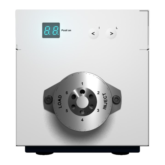
Quick Links
Advertisement
Table of Contents

Related Manuals for Knauer BlueShadow V6


Summary of Contents for Knauer BlueShadow V6
- Page 1 BlueShadow Valves V6-V16 Service manual V7696A HPLC...
-
Page 2: Table Of Contents
Table of contents Table of contents Safety for service technicians ........Protective measures . -
Page 3: Safety For Service Technicians
Safety for service technicians Safety for service technicians Checking intended use Only use the device for applications that fall within the range of the intended use. Otherwise, the protective and safety equipment of the device could fail. The installation manual is an addition to the existing device manual;... -
Page 4: Protective Measures
Disassembling the housing Protective measures The following applies for all repairs on the device: Hazard symbol Warning instructions DANGER! Danger due to toxic, caustic or radioactive substances due to con- tamination of the device. The customer must ensure that the device has been thoroughly deconta- minated before repairs are performed. - Page 5 Disassembling the housing Removing the device Process Figure hood Legend 1. Remove the two hexagon screws on A Hexagon screws the rear side of the device. Fig. 1 Unscrew the device hood Legend 2. Push back the device hood approx. 2 cm; A Device hood using both hands, lift to remove.
-
Page 6: Removing The Sides Of Device
Disassembling the housing Removing the sides of device The two side panels are inserted into the front side of the housing. Prerequisite The device hood is open. Procedure Lift the side up and tilt out Duration Approx. 3 min Level of difficulty Level 2 (from 1 to 7, very easy to very difficult) Removing the sides Process... -
Page 7: Replacing The Fan
Replacing the fan Replacing the fan Danger of electric shock! WARNING! Switch off the power supply! Pull the power plug! Legend A PIN connector B Fan with power cable Fig. 5 Removing the fan Prerequisite The device hood has been removed. ... -
Page 8: Installing The Fan
Replacing the fan Removing the fan Process Figure 1. Remove the fan power supply cable from the PIN connector (A) on the main board. 2. Open the cable holder (B). 3. Use the wrench to hold the nuts inside the Fig. - Page 9 Replacing the fan Installing the fan Process Figure 1. Insert the four rubber dampers (D) into the rear panel of the device. 2. Set the fan (A) onto the rear panel of the device, so that the arrow on the fan indi- cating the direction of air suction corresponds with the arrow in the...
-
Page 10: Installing And Removing The Valve Drive
Installing and removing the valve drive Installing and removing the valve drive The valve drive is composed of the following subassemblies Legend Slotted disk (A) photoelectronic sensor (B) gearbox and motor (C) Fig. 8 Valve drive Note: Together, the gearbox and the motor form a single subas- sembly. -
Page 11: Removing The Gearbox And Motor
Installing and removing the valve drive Tools 3.0 mm and 2.5 mm Allen wrenches Cross-head screwdriver size 1 Oscilloscope Soldering iron Duration Approx. 15 min Level of difficulty Level 3 (from 1 to 7, very easy to very difficult) Removing the gearbox and motor Process Figure... - Page 12 Installing and removing the valve drive Process Figure 3. Unscrew both of the inner 2.5 mm hexa- gon socket screws (A,B) in order to lift off the slotted disk. Unfastening the 6P or Fig. 11 16P slotted disk 4. Using a cross-head screwdriver, loosen the three Phillips- head screws hold-...
-
Page 13: Installing The Gearbox And Motor
Installing and removing the valve drive Installing the gearbox and motor Note The gearbox and motor are always installed with a clearance of 0.25–0.5 mm so that these have sufficient play during operation Always leave 0.2 mm clearance from the drive mounting when installing the slotted disk ... -
Page 14: Installing The Motor And Gearbox
Installing and removing the valve drive Installing the motor and gearbox Process Figure 1. Installing the subas- sembly Fig. 14 Slotted disk (A), photoelec- tric sensor (B), gearbox (C), and motor (D) 2. Rotate the drive axle with setup marking (B) and the slotted disk with adjustment opening (A) -
Page 15: Adjusting Position 1 Of The Valve
Installing and removing the valve drive Adjusting position 1 of the valve Process Illustration/description 1. Position the alignment tool (A) and secure in place with the hexagon socket screws Fig. 16 Alignment tool 2. The setup mark- ing (B) needs to be centered in the alignment tool... -
Page 16: Installation And Connection
Installation and connection Installation and connection Mounting of the valve on the valve drive Delivery ex works All valve drives are delivered with a ready-mounted injection or multiposition valve. For repeat orders, the electrical valves are delivered with included adapter plate. Screw the adapter plate to the back side of the valve. -
Page 17: Screw The Valve Onto The Valve Drive
Installation and connection Screw the valve onto the valve drive Caution! Risk of mix-up! Always mount the switch or injection valve onto the matching valve drive. An operation of the valve with the wrong valve drive can block the eluent flow. Damage to the device or the system might be the consequence. -
Page 18: Mounting Plate For Valves And Column Holder
Installation and connection Mounting plate for valves and column holder Valves can be attached on the side of housings of pumps, detec- tors, valves, or multifunction modules (assistant) with a mount- ing plate (order number G6725) and 4 screws. Legend A. -
Page 19: Inserting The Needle Seal In The Syringe Connection
Installation and connection Prerequisite The capillary end was cut off cleanly and at a right angle to the capillary axis with a tube cutter (order number A0569). Connecting the capillar- Steps Figure 1. Place the biconical seal (C) on the nee- dle seal (B). -
Page 20: Multifunction Module 'Assistant
Installation and connection The injection valve is prepared for the injection of sample solu- tions in the sample loop via a glass syringe with luer lock: Legend A. Injection valve B. Syringe connection C. Needle seal D. Sample loop E. Metal cannula with luer lock F. -
Page 21: Connection Of The Pump With Other Devices
Installation and connection Connection of the pump with other devices Control of the pump with chromatography software The valves can be controlled individually or as part of a HPLC system by means of a computer and chromatography software. Local area network and automatic configuration The valve is controlled either by means of the function keys on the front of the device or by means of the chromatography soft-... -
Page 22: Remote Terminal Strip
Installation and connection The connections at the interfaces are detected automatically by the device. The LAN connection and the RS-232 interface can be used for the valves. The remote control is often used when the devices are employed in an analytical system whose chromatography software does not support the driver software of the manufac- turer. -
Page 23: Home
Installation and connection HOME If the valve is controlled by HOME , it has priority over control via RS-232 or manual operation. As long as the switch-off signal is not cancelled, the valve cannot be started. The indicator of the position flashes to indicate that the start of the valve is pre- vented by an external signal. -
Page 24: Binary Code
Installation and connection Binary code Prerequisite: The DIP switch of the device was set for the binary control. A binary code is entered during binary control so that the valve can be set externally in the correct position (nominal position). Position BIN 0... -
Page 25: Replacing Eeprom Or Motherboard
Replacing EEPROM or motherboard Replacing EEPROM or motherboard EEPROM The EEPROM chip stores the serial numbers, operating hours and error messages from the device. Various solutions are availa- ble for transmitting the EEPROM data: Insert the EEPROM from the previous motherboard onto the new motherboard ... -
Page 26: Replacing The Eeprom
Replacing EEPROM or motherboard Replacing the EEPROM Caution! Microelectronic components can become damaged by electrostatic discharge (ESD) when touched. Take precautions against electrostatic discharge! Process Figure 1. Make a digital photo of the cabling on the motherboard to help reconnect the cables later on. - Page 27 Replacing EEPROM or motherboard 7. Install a new EEPROM with the correct ori- entation (A) and observe the mar- kings on the socket and EEPROM! Fig. 29 Insert the EEPROM with the correct orientation 8. Before pressing it in, check the positioning of the pins (A) so that none become bent.
-
Page 28: Troubleshooting
Troubleshooting Troubleshooting First measures 1. Check all cabling 2. Check all screw fittings 3. Check whether air has gotten into the supply lines 4. Check device for leaks 5. Observe system messages on the display Possible problems and rectifications Problem Solution The slotted disk Replace the gear-motor subassembly. -
Page 29: Spare Parts
Spare parts Spare parts Valves and valve drives V6-V16 Order number Name G1278 Motor complete with cable and 66:1 ratio G1279 Motor complete with cable and 134:1 ratio G2520 Sensor board with photoelectric sensor K0175 Special microchip EEPROM for saving data G2519XA Motherboard valve drive... - Page 30 © Wissenschaftliche Gerätebau Dr. Ing. Herbert Knauer GmbH All rights reserved. The information in this document is subject to change without prior notice. Translation of the original German edition of this manual. 2011-10-31 Printed in Germany. www.knauer.net HPLC · SMB · Osmometry Wissenschaftliche Gerätebau...
Need help?
Do you have a question about the BlueShadow V6 and is the answer not in the manual?
Questions and answers