Table of Contents
Advertisement
Quick Links
Iwaki
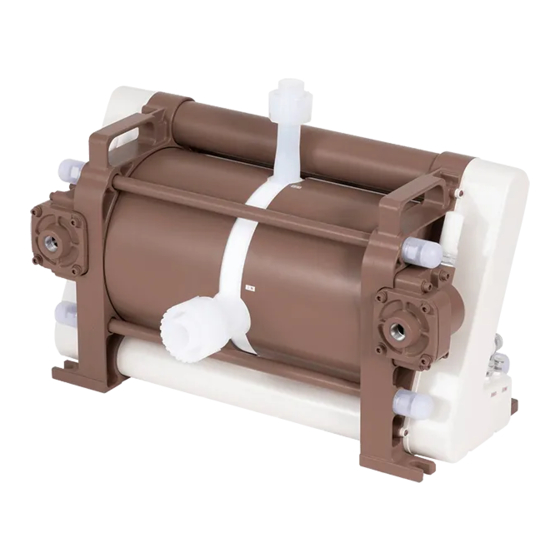
Pneumatic Drive Bellows Pump
FLP-75W
Instruction manual
Thank you for choosing our product.
Please read through this instruction manual before use.
This instruction manual describes important precautions and instruc-
tions for the product. Always keep it on hand for quick reference.
©2014 IWAKI CO., LTD.
Advertisement
Table of Contents

Related Manuals for IWAKI PUMPS FLP-75W


Summary of Contents for IWAKI PUMPS FLP-75W
- Page 1 Iwaki Pneumatic Drive Bellows Pump FLP-75W Instruction manual Thank you for choosing our product. Please read through this instruction manual before use. This instruction manual describes important precautions and instruc- tions for the product. Always keep it on hand for quick reference.
-
Page 2: Order Confirmation
Order confirmation Open the package and check that the product conforms to your order. If any problem or inconsistency is found, immediately contact your distributor. a. Check if the delivery is correct. Check the nameplate to see if the information such as model codes are as ordered. b. -
Page 3: Table Of Contents
Contents Order confirmation ............................2 Safety instructions ..............7 Warning ................................8 Caution ................................9 Precautions for use ............................ 11 Overview ...................12 Introduction ..............................12 Pump structure & Operating principle ...................... 12 Features ..............................13 Operation mode ............................13 Safety functions ............................13 Part names .............................. - Page 4 Before air piping ............................25 Solenoid valve (SV) ..........................25 Regulator ............................. 25 Air line piping layout (FLP-75W) ......................25 Supply air port I.D..........................26 Effective cross-sectional area ........................27 Effective cross-sectional area required for decompression process ..........27 Composite effective cross-sectional area required for compression process ........
- Page 5 User PLC ............................. 36 Proximity switch/Displacement sensor/Leak sensor ................38 Electropneumatic regulator or Pressure sensor .................. 39 Operation ................. 40 Before operation ............................40 Programming menu ............................ 42 Basic key operation ..........................43 Main menu ............................43 Pump operation ............................44 Pump model selection ..........................44 Teaching ..............................45 Manual operation .............................46...
- Page 6 Specification/Outer dimension ........................67 Specification ............................. 67 Pump ..............................67 LPC-1 controller ..........................67 Proximity switch ..........................68 Displacement sensor .......................... 68 Leak sensor ............................68 Outer dimension ............................69 FLP-75W .............................69 LPC-1 controller ..........................69 Part names ............................... 70 FLP-75W ............................. 70 Contents...
-
Page 7: Safety Instructions
Safety instructions Read through this section before use. This section describes important information for you to prevent personal injury or property damage. ■ Symbols In this instruction manual, the degree of risk caused by incorrect use is noted with the follow- ing symbols. -
Page 8: Warning
WARNING Turn off power before work Risk of electrical shock. Be sure to turn off power to stop the pump and related devices before service is performed. Let other people know about the situation by displaying a notice such as "POWER OFF (Maintenance)" Requirement near the power switch. -
Page 9: Caution
CAUTION Do not lift the pump by gripping the right-and-left cylinder head cov- ers or the top-and-bottom covers The pump can drop unintentionally as one of those parts breaks. Hold the Requirement pump by the handgrips to lift it up. Qualified personnel only The pump should be handled or operated by qualified personnel with a full understanding of the pump. - Page 10 CAUTION Static electricity When low electric conductivity liquids such as ultra-pure water and fluor inactive liquid (e.g. Fluorinert ) are handled, the static electricity may be generated in the pump and may cause static discharge. Take counter- Requirement measures to remove the static electricity. Wear part replacement Follow instructions in this manual for wear part replacement.
-
Page 11: Precautions For Use
Precautions for use • During transit: –Do not hit/wet the package. –Do not place the package lateral/up side down. – Do not stack the package on top of another. Prohibited • Electrical work should be performed by a qualified electrician. Otherwise, personal injury or property damage could result. -
Page 12: Overview
Pump structure & Operating principle The FLP-75W is a pneumatic drive pump with a pair of bellows and is controlled with the LPC-1 controller. The special design of this pump alone reduces discharge pulsation without the assistance of a dampener, as low as the combination of existing models and a dampener can achieve. -
Page 13: Features
Features ● Low discharge pulsation Displacement sensors and proximity switches monitor bellows movement for the LPC-1 controller to deter- mine the optimal time to offset flow pulsations one after the other without the support of a dampener. ● No need for a pressure and a flow sensor Displacement sensors and proximity switches alone monitor bellows movement. -
Page 14: Part Names
Part names Pump Handgrip Outlet Silencer Cable outlet for the: laser displacement sensor, proximity switch, and leak sensor Supply air port Inlet Displacement sensor cooling air inlet (I.D. 6mm) Displacement sensor cooling air outlet (I.D. 6mm) Supply air port Quick exhaust valve Base Always anchor the pump through the base. -
Page 15: Lpc-1
LPC-1 ■ Control panel START/STOP key MENU key ENTER key RETURN/RESET key SELECT key UP/DOWN key START/STOP key Used to start/stop the pump in MANU mode. The START/STOP LED lights during operation. The pump stops at any time during MANU or AUTO mode if the key is pressed and held for 2 seconds (emergency stop) and returns to the main menu after 7 seconds. -
Page 16: Leds
■ LEDs POWER LED (green) TEACHING LED (orange) LEAK LED (red) FAST LED (red) TIME UP LED (red) LIFE LED (red) E-P Reg LED (red) START/STOP LED (green) POWER LED Lights green as powered on. TEACHING LED Lights orange when the LPC-1 is measuring the max stroke length and the origin position (teaching) by select- ing "2. -
Page 17: Operating Conditions
Operating conditions Pump stroke Operation over the maximum stroke rate can take in a large amount of air during operation. Set the maximum allowable speed at each supply air pressure range as a fast alarm speed into the LPC-1 controller. Stroke rate at each supply air pressure Items Spec... -
Page 18: Operation And Stoppage
Operation and Stoppage ■ During operation Make sure a suction and a discharge line are fully opened. ■ When stopping the pump • Before stopping the pump, make sure the discharge line is open to the atmosphere. Otherwise, the bellows may deform. -
Page 19: Identification Codes
Identification codes Each code represents the following information. FLP - 75 W H C 2 - 01 a c d e a. Series name FLP-W : Medium & high liquid temperature (low pulsation) b. Bellows size c. Allowable liquid temperature range H : 5-180ºC d. -
Page 20: Installation
Installation This section describes the installation of the pump, piping and wiring. Read through this section before work. To operate this pump, a 5-port solenoid valve and LPC-1 controller is needed. Points to be observed Observe the following points when installing the pump. •... - Page 21 Select a location Select a level location, free from vibration, that won't hold liquid. Anchor the pump so it doesn't vibrate. See page 11 as well. Flooded suction application is recommended. * Observe the maximum suction lift (1m) in suction lift application. Keep the pump footprint clear so nothing applies stress to the un- der cover.
-
Page 22: Liquid Line Piping
Liquid line piping An Nippon pillar packing Super 300 type 1-¼" union nut/sleeve is originally equipped to the inlet of the pump and that of 1" union nut/sleeve to the outlet of the pump. Use an applicable tube of O.D. 31.8mm × I.D. 28mm to the inlet and that of O.D. 25.4mm × I.D. 22.2mm to the outlet for the connection between the pump and your piping system. -
Page 23: Suction Line
Suction line ■ Flooded suction In flooded suction application, observe the pump inlet N.D. of 1-1/4" (O.D. 31.8mm × I.D. 28mm), the suction line can be laid to the maximum length of 5.3m with no elbows. * If five 90° elbows (0.6m resistance at each elbow) are used, the maximum length is shortened to 2.3m. In suction lift application, observe the maximum suction lift of 1m (operation with clan water at ambient tem- perature and the max spm). -
Page 24: Degassing
Degassing Gas bubbles are generated when a strong acid is fed into the reaction tank or liquid is transferred through a narrow tube. If such bubbles enter the bellows, the pump runs with entrained gas, increasing stroke rate or dis- turbing liquid transfer. -
Page 25: Air Line Piping
Our existing pneumatic pumps use one solenoid valve to supply air to both right-and-left air chambers in turn, but then the FLP-75W needs two 5-port solenoid valves at each air chamber. Plug the normally-open out port and exhaust port of the solenoid valves, or the pump will not run correctly. -
Page 26: Supply Air Port I.d
Points to be observed Observe the following points when building up a supply air line. • A fluctuation of supply air pressure affects the stroke rate and the flow rate. Install a regulator to maintain the supply air pressure constant. •... -
Page 27: Effective Cross-Sectional Area
Effective cross-sectional area Effective cross-sectional area of the air piping, silencer, solenoid valve or so determines the performance of pressurization and depressurization in the air chambers. The less effective cross-sectional area than the required square millimetres (independently for decompression and compression) prevents the contraction and expansion of the bellows and eventually causes a poor liquid flow and significant pulsation. -
Page 28: Air Supply Capacity Of Pneumatic Devices
■ Air supply capacity of pneumatic devices 1. Pneumatic devices In the field of pneumatic devices, the term “effective cross-sectional area” is used to indicate the amount of an air flow which each device actually can deliver. In general, the air flow increases as effective cross- sectional area becomes larger. -
Page 29: Air Line Piping Diagram
Air line piping diagram The diagram below is a general layout of an air-line. Pump a. Silencer on the Built in the quick exhaust valve (QEV) Always connect the SMC AN40-04 silencers directly to both right and left QEVs built in the pump. b. - Page 30 f. Silencer on the solenoid valve Use of the SMC AN40-04 is recommended. Connect the silencer to the normally-closed exhaust port 5(R of the solenoid valve when the SMC SY9140-5-04-X90 is used. g. Piping between the SV and the silencer. Do not use a tube for the connection.
-
Page 31: Electric Wiring
Electric wiring Two 5-port solenoid valves and the LPC-1 controller is required. Points to be observed Observe the following points during wiring work. • Electrical work should be performed by a qualified electrician. Always observe applica- ble codes or regulations. •... -
Page 32: Wiring Diagram (Lpc-1)
Wiring diagram (LPC-1) CN1 24VDC power IN CN2 Power OUT Not used. CN3 Solenoid valve signal OUT Right-and-left SV are connected. CN4 Alarm signal OUT An alarm signal is sent out to a user PLC. CN5 Control signal IN User PLC can control the LPC-1 via this terminal. CN6 Sensor signal IN Displacement sensors, proximity switches and leak sen- sors are connected. -
Page 33: Wiring Diagram (Normal Operation With A Single Solenoid Valve)
Wiring diagram (normal operation with a single solenoid valve) See page 36 for the wiring of the double solenoid valve (CN3). Black Black Left regulator Right regulator CN1 CN2 CN3 pressure sensor pressure sensor Blue Blue SMC PSE540A-01 SMC PSE540A-01 Brown Brown PIN10 INPUT Brown wire... -
Page 34: Wiring Diagram (Feedback Control With A Single Solenoid Valve)
Wiring diagram (feedback control with a single solenoid valve) White White Green Green Left electropneumatic Right electropneumatic Black Black CN1 CN2 CN3 CN4 regulator regulator Shield Shield CKD EVD3500-010AN-_ _-3 CKD EVD3500-010AN-_ _-3 PIN18 OUTPUT Sky blue wire PIN10 INPUT Brown wire Blue Blue PIN14 SGND Gray wire... -
Page 35: End Terminals
End terminals ■ Power line CN1 Power voltage input (controller) Connector # Connector manufacturer Housing VHR-4N Contact SVH-21T-P1.1 Applicable power lead AWG #22-#18 H JST Pin # Assignment F.G. (Frame Ground) N.C. (Not used) +24V in (24VDC power input) * Capacity of the 24VDC power supply must be 2A or more. -
Page 36: Double Solenoid Valve
■ Double solenoid valve CN3 SV output (controller) Connector # Connector manufacturer Housing PHDR-8VS Contact SPHD-001T-P0.5 Applicable power lead AWG #26-#22 Pin # Assignment Right SV control output (Normally closed) 24VDC (Normally closed) Left SV control output (Normally closed) 24VDC (Normally closed) Right SV control output (Normally open) 24VDC (Normally open) - Page 37 CN5 Control signal input (controller) Connector # Connector manufacturer Housing PHDR-10VS Contact SPHD-001T-P0.5 Applicable power lead AWG #26-#22 Pin # Assignment START/STOP Alarm reset Dry running start/stop Electropneumatic regulator error Not used Not used * Pin 9 and 10 are not used. Use the combination of pin 1 &...
-
Page 38: Proximity Switch/Displacement Sensor/Leak Sensor
■ Proximity switch/Displacement sensor/Leak sensor CN6 Sensor input (controller) Connector # Connector manufacturer Housing PHDR-24VS Contact SPHD-001T-P0.5 Applicable power lead AWG #26-#22 Pin # Assignment Right proximity switch 24VDC Left proximity switch 24VDC Not used Not used Right proximity switch GND Left proximity switch GND Not used Not used... -
Page 39: Electropneumatic Regulator Or Pressure Sensor
■ Electropneumatic regulator or Pressure sensor CN7 Electropneumatic regulator/pressure sensor input/output (controller) Connector # Connector manufacturer Housing PHDR-20VS Contact SPHD-001T-P0.5 Applicable power lead AWG #26-#22 Pin # Assignment Right electropneumatic regulator/pressure sensor 24VDC Left electropneumatic regulator/pressure sensor 24VDC Not used Not used Right electropneumatic regulator/pressure sensor GND Left electropneumatic regulator/pressure sensor GND... -
Page 40: Operation
Operation This section describes pump operation and programming. Run the pump after pipework and wiring are completed. Before operation Always check the following items before the first-time operation or resuming operation after a long period of stoppage. Check if electric wiring is made correctly. Check the wiring of proximity switches, leak sensors, solenoid valves, displacement sensors and elec- tropneumatic regulators (pressure sensors). - Page 41 Tighten stud bolts. Stud bolts may loosen during storage or transit due to temperature fluctuation. Loose stud bolts can cause an air leak from the joint of the cylinder head and pump head. Be sure to tighten the M14 nuts by 30N•m to secure the stud bolts before operation.
-
Page 42: Programming Menu
Programming menu Operation at each mode is individually set and controlled by the LPC-1 controller. Make proper setting to ensure optimal operation. The controller will show version information for 3 seconds after power is turned on and then nine main-menu options. Sub-menu options will be available at each main-menu options. -
Page 43: Basic Key Operation
Basic key operation Operation control or setting with keypad operation. ■ Main menu The main menu has 9 options. Move the cursor between the options with the UP and DOWN keys and push the ENTER key to make a selection. The sub-menu options also can be selected in the same way. The follow- ing shows the steps to enter the AUTO mode through basic key operation. -
Page 44: Pump Operation
Pump operation The start/stop of the pump is controlled by the LPC-1 controller in MANU mode or a user PLC in AUTO mode. Points to be observed Before operation in your system, conduct a trial run with pure water (or chemical liquid) to flush out particles or to measure metal ion level. -
Page 45: Teaching
Teaching During the teaching behaviour, the LPC-1 controller measures the maximum possible stroke length and the ori- gin position (0 stroke length) with the right-and-left displacement sensors. The teaching process is necessary to keep synchronization between the pump and the controller. NOTE •... -
Page 46: Manual Operation
The right display shows up and the TEACHING LED flashes when the right (or left) proximity switch does not detects the right (or left) connecting plate within 10 seconds during teaching behaviour. * Check if air lines and electric wiring are correctly made. * Check if liquid lines are kept open. - Page 47 Select "3. PUMP DRIVE" in the main menu and push the ENTER key. Use the UP and DOWN keys (or the SELECT key) to choose "YES" and push the EN- TER key if feedback control is required. Or choose "No". See page 52 for feedback control.
-
Page 48: Operation Stop
■ Operation stop Points to be observed • Before stopping the pump, release the pressure from the discharge line. Otherwise, the bellows may deform. • Do not close a discharge valve as stopping the pump. An impact pressure may damage the bellows or a connecting plate. -
Page 49: Auto Operation
AUTO operation Run or stop the pump with the external signal (CN5 PIN1 START/STOP signal) from user PLC. Select "7. MANU or AUTO" in the main menu and push the ENTER key. Select "AUTO" and push the ENTER key. The controller returns to the main menu. Select "3. -
Page 50: Display Information
Display information ■ Operation display * Push the RETURN/RESET key to turn off the Alarm LED if it lights. A calculated flow rate by liquid volume per shot and the number of shots Pump model Stroke rate Regulator air pressure If electropneumatic regulators instead of normal regulators are used to the operation with no feedback control, the... -
Page 51: Operation Programming
Operation programming Select "4. SETTING" for programming the feedback control (1. QUANT.CONST.CTRL), alarm output behaviour (2. ALARM), setting/mode confirmation (3. SET VALUE CONFIRM) and defaulting the LPC-1 (4. RESET ALL DATA). Select "4. SETTING" in the main menu and push the ENTER key. Sub-menu options will appear. -
Page 52: Feedback Control (4. Setting: 1. Quant. Const. Ctrl)
Feedback control (4. SETTING: 1. QUANT. CONST. CTRL) Program a target flow rate, the set pressure of the electropneumatic regulators and liquid volume per shot. An electropneumatic regulator is always required to both the right and left air lines between the SV and the REG in order to adjust the amount of supply air to the pump and to keep the target flow rate under pressure fluctuation. -
Page 53: Electropneumatic Regulator (Epreg) Setting
■ Electropneumatic regulator (EPREG) setting Set the starting pressure, minimum/maximum allowable supply air pressure to the LPC-1 controller. Select "2. E-P REGULATOR" (electropneumatic regulator setting) in the sub menu and push the ENTER key. Select each setting option and push the ENTER key. -
Page 54: Liquid Volume Per Shot Setting
■ Liquid volume per shot setting Set the liquid volume per shot to the LPC-1 controller. The flow rate on the operation display is calculated by multiplying the liquid volume by the number of pump shots. Select "3. 1 shot d CAPA" in the sub menu and push the ENTER key. -
Page 55: Alarm Output (4. Setting: 2. Alarm)
Alarm output (4. SETTING: 2. ALARM) Program alarm output behaviours of Time-up, Fast and Life alarms. ■ Time up alarm setting (Default: 20sec) The LPC-1 controller outputs the time-up alarm to the user PLC and the TIME UP LED lights when either right or left proximity switch does not detect the connecting plate within the set time. -
Page 56: Setting Confirmation (4. Setting: 3. Set Value Confirmation)
Set the time up, fast and life alarm behaviour and push the ENTER keys. Move between digits with the SELECT key and change numerical values with the UP and DOWN keys. When setting the time up alarm, enter the maximum allowable time for a proximity switch to detect the connecting plate. -
Page 57: Default Setting (4. Setting: 4. Reset All Data)
Select one of the sub-menu options and push the ENTER key to check settings. Push the ENTER, RESET, SELECT, UP or DOWN key to return to the confirmation sub- menu or the MENU key to return to the main menu. Default setting (4. -
Page 58: Keypad Lock (5. Key Protect)
Keypad lock (5. KEY PROTECT) Keypad lock can be active for the prevention of erroneous key operation. NOTE Any key operation is not acceptable when the keypad lock is active. In an emergency, press and hold the start/ stop key for 2 seconds. The pump enters a wait state and stops running. ■... -
Page 59: Total Number Of Pump Shots Confirmation/Cancellation (6. Total Count)
Total number of pump shots confirmation/cancellation (6. TOTAL COUNT) Default the accumulated reciprocation times in the TOTAL COUNT1 and 2 through the following procedure as necessary (one reciprocation time means two pump shots.). TOTAL COUNT3 can not be defaulted. * TOTAL COUNT 2 and 3 are not linked to the life alarm output. The life alarm works based on the accumulation in TOTAL COUNT1. -
Page 60: Regulator Set Pressure Confirmation (8. Pressure Sensor)
Regulator set pressure confirmation (8. PRESSURE SENSOR) The greater difference between the right and left regulator set pressure, the more pulsation it becomes. Be sure to keep the same set pressure to both regulators (max allowable deviation is ±0.01MPa). Select "8. PRESSURE SENSOR" and push the ENTER key. When a pressure sensor is provided to the regulator or directory on the supply air line in operation: When a pressure sensor is not provided: When an electropneumatic regulator is provided and the pump stops:... -
Page 61: Alarm Output Cancellation (9. Alarm Reset)
Alarm output cancellation (9. ALARM RESET) Stop the alarm output and turn off the leak, time-up, life or E-P Reg LED through the following procedure. Select "9. ALARM RESET" and push the ENTER key in the main menu. Select "YES" and push the ENTER key. The LPC-1 controller stops outputting the alarm signal and turns off the leak, time-up, life or E-P Reg alarm LED. -
Page 62: Maintenance
Maintenance This section describes troubleshooting, inspection, specification and dimensions. Points to be observed Observe the following points during maintenance work. • Follow instructions in this manual for replacement of wear parts. Do not disassemble the pump beyond the extent of the instructions. •... - Page 63 States Possible causes Points to be checked Solutions Bellows rupture ○ Supply air pressure ● Replace the bellows if (Leak alarm output) ○ Stroke rate damaged.* ○ Liquid temperature ● Observe pump spec and ○ If discharge line pressure composite effective cross is released as soon as the sectional area.
- Page 64 States Possible causes Points to be checked Solutions Supply air pressure or air ○ If proper air line I.D. is ● Reset the system. flow is too low. selected if two or more ● Adjust the regulator set pumps are installed. pressure as necessary.
-
Page 65: Inspection
Inspection Perform daily and periodic inspection to keep pump performance and safety. Daily inspection Check for a leak or any other abnormality during operation. If you notice any abnormal or dangerous condi- tions, suspend operation immediately and inspect/solve problems according to "Troubleshooting". Replace- ment of wear parts is necessary at periodic intervals. -
Page 66: Wear Part List
Wear part list To run the pump for a long period, wear parts need to be replaced every one year or every time when pump performance has reduced. Contact your distributor with the following information for wear part replacement. 1. Part names and part number (See "Part names" on page 70.) 2. -
Page 67: Specification/Outer Dimension
Specification/Outer dimension Specification Information in this section is subject to change without notice. ■ Pump Items Spec Ambient temperature/humidity 0-60ºC/30-60%RH (non-condensing) Storage temperature/humidity -10-60ºC/20-70%RH (non-condensing) Installation location Indoor (no dusty environment) Operation rating Intermittent/continuous Driving method Pneumatic drive O.D. 31.8 × I.D. 28.0 mm PFA tube Inlet tube connection with a Super 300 type 1-¼"... -
Page 68: Proximity Switch
Items Spec Number of input channels Input voltage Input current 5mA(min)/10mA(max) Digital input Insulation Photocoupler insulation Withstand voltage 500VAC/min (breaking current 0.5mA or below) Insulation resistance 50MΩ or more Number of channels to the EPREG Output voltage range to the EPREG 0-10V Output isolation None... -
Page 69: Outer Dimension
Outer dimension ■ FLP-75W Weight: 42kg Supply air port 2×Rc1/2 14.5 14.5 96.5 ■ LPC-1 controller 4×ø4.5 4×ø4.5 4×ø4.5 Panel cutout Specification/Outer dimension... -
Page 70: Part Names
Part names ■ FLP-75W Leak sensor Quick exhaust valve Exhaust air port Rc1/2 Supply air port Rc1/2 Name Q'ty Material Remarks Name Q'ty Material Remarks 1 Pump head 1 PTFE 45 Proximity detector 2 Suction tube 1 PFA 46 Proximity spacer... - Page 71 Specification/Outer dimension...
- Page 72 IWAKI Norge AS TEL : (47)23 38 49 00 FAX : 23 38 49 01 China IWAKI Pumps (Guangdong) Co., Ltd. TEL : (86)750 3866228 FAX : 750 3866278 Singapore IWAKI Singapore Pte. Ltd. TEL : (65)6316 2028 FAX : 6316 3221 China GFTZ IWAKI Engineering &...
Need help?
Do you have a question about the FLP-75W and is the answer not in the manual?
Questions and answers