
Subscribe to Our Youtube Channel
Related Manuals for IWAKI PUMPS FS-15HT1


Summary of Contents for IWAKI PUMPS FS-15HT1
- Page 1 IWAKI Pneumatic Drive Bellows Pump FS Series Instruction Manual Read this manual before use of product...
-
Page 2: Table Of Contents
Thank you for having selected IWAKI's Pneumatic Drive Bellows Pump FS Series. This instruction manual, which is divided into 5 sections, namely “Safety Section,” “Outline Section,” “Installation Section,” “Operation Section” and “Maintenance Section,” deals with the correct handling and operation procedures for the pump. To make maximum use of the pump and to ensure safe and long operation of the pump, please read this manual thoroughly and carefully prior to operating the pump. -
Page 3: Important Instructions
Important Instruction For the Safe and Correct Handling of the Pump • Read the "Safety Instructions" sections carefully to prevent accidents involving your customers or other personnel and to avoid damage or loss of other assets. Always follow the instructions and advice found in these sections. -
Page 4: Safety Section (Instructions To Prevent Accidents)
Safety Section WARNING Look around • Make sure there is no one around the pump when connecting the power cable. The power supply switch is not provided on the pump. Connecting the power cable and supply air to the pump starts pump operation. Do not remodel pump •... - Page 5 Safety Section CAUTION • Lifting pump If a lifting rope or chain breaks or is cut when lifting the pump, a fatal or serious injury to person may result from the accident. Select a lifting rope or chain which is strong enough for the load of the pump.
- Page 6 Safety Section CAUTION Supply air pressure • Supply air pressure must be maintained within specified supply air pressure range. Otherwise, the bellows may be deformed. Pump type Liquid temperature range Supply air pressure range 5-50 deg.C 0.147-0.490 (MPa) FS-15·30·60 51-100 deg.C 0.147-0.294 (MPa) 101-180 deg.C 0.147-0.196 (MPa)
- Page 7 Safety Section CAUTION • Stopping pump operation · When stopping pump operation, release the pressure on the discharge side first. Otherwise, the bellows may be deformed due to the residual pressure on the pump discharge side. · If a valve is provided on the discharge side, do not close the valve upon stopping the pump.
-
Page 8: Outline Of Product
OUTLINE OF PRODUCT This section deals with operating principle, type and specifications of the pump as an introduction of the pneumatic drive bellows pump. 1. Unpacking and Inspection ....7 2. Operating Principle ......7 3. Identification Codes ......8 4. -
Page 9: Unpacking And Inspection
1. Unpacking and Inspection After unpacking the product, check the following points to ascertain that the product is exactly as you ordered. If you find anything wrong, please contact your dealer. [1] Does the model indicated on the nameplate repre- sent what you ordered? [2] Has the pump or any part of it been damaged as the result of an accident or mishandling in transit? -
Page 10: Identification Codes
1: Mechanical connection type 2: Weld type h Special specifications No symbol : Standard : Special specifications (01, 02 ······ ) 4. Specifications Item FS-15HT1/T2 FS-30HT1/T2 FS-60HT1/T2 Max. discharge volume (Note 1) 15 L/min 30 L/min 55 L/min Max. stroke speed (Note 2) -
Page 11: Outer Dimensions/Mass
5. Outer Dimensions/Mass FS-15HT Mass : 6.3kg Unit : mm 2- 12.7 × 9.52 φ φ 15.5 AIR SUP. 2-Rc1/4 (100) FS-30HT Mass : 11.7kg Unit : mm 2- 19 × 16 φ φ AIR SUP. 2-Rc1/4 (100) - 9 -... - Page 12 FS-60HT Mass : 21.5kg Unit : mm 2- 25 × 22 φ φ AIR SUP. 2-Rc3/8 (100) - 10 -...
-
Page 13: Names Of Parts And Structure Of Pump
6. Names of Parts and Structure of Pump FS-15 · 30 · 60HT1 34 33 17 21 19 20 50 49 SECTION : N N : LEAK SENSOR Parts Name Q'ty Material Remarks Parts Name Q'ty Material Remarks Pump head PTFE 28 Proximity switch Tube... - Page 14 FS-15 · 30 · 60HT2 40 39 38 SECTION : N N : LEAK SENSOR Parts Name Q'ty Material Remarks Parts Name Q'ty Material Remarks Pump head PTFE 28 Proximity switch Tube 29 Pan head screw Stainless steel Bellows PTFE 30 O ring Valve case 31 Cylinder head cover...
-
Page 15: Description On Body And Label
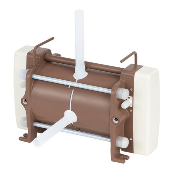
7. Description on Body and Label Caution When cleaning the pump be careful not to wipe the labels or the pump body with solvent. Discharge port Handle to carry OUT label IN label Suction port Air port Name plate Cord Cord for proximity switch and electrode to be connected to controller. -
Page 16: Installation Section
INSTALLATION SECTION This “Installation Section“ must be thoroughly understood by the user before actually installing the pump. Do not start your installation work unless you confirm your understanding of the entire set of descriptions in this section. 1. Before Use ........15 2. -
Page 17: Before Use
1. Before Use For reliable pump performance to suit your application purposes, full safety measures should be taken for the pump unit and the entire system. The following information, including the points to be observed in the handling of the pump, deals with the measures to ensure the safe operation of the system. Please read the description carefully. - Page 18 Points to be Observed Description ™ Liquids to be handled with care · Stripper ¡ Some types of strippers may cause cracks in bellows or piping · Hydrazine (PFA) at an early stage. (Contact Iwaki for a different warranty · Fuming sulfuric acid period applied for such liquids.) ·...
- Page 19 Other precautions to be taken [1] Surface temperature of pump Warning Touching the pump or piping whose surface temperature is extremely high due to the circulation of a hot liquid is very dangerous. Always arrange adequate hand-protective measures when engaged in feeding a hot liquid into the pump.
-
Page 20: Installation, Piping, And Wiring
Direct the discharge port upward and the suction port horizontally. Use anchor bolts to fasten the pump firmly in position. [4] Bolt tightening Tighten the bolts on the housing upon installation by applying the following fastening torque. Fastening torque for FS-15HT1: 9.8N FS-15HT2: 4.9N • •... -
Page 21: Liquid Tubing
2.2 Liquid Tubing The standard tubes for both the discharge and suction ports are PFA tubes. Connect the tubes as described below [1] Pump port diameters and materials Attached to tube from pump head To piping line The standard material of the pump discharge port and suction port is PFA tubing. - Page 22 [3] When installing a valve on the suction pipe, select a valve with an orifice larger than the inner diameter of the said pipe. A smaller orifice may result in a larger suction piping resistance or an increased chance for the valve to be clogged with a crystallized substance.
- Page 23 2.2.3 Air elimination measures When strong acid liquid is fed into the reaction tank or such liquid is circulated through narrow tubing, bubbles are generated. If such bubbles are mingled in the liquid that is sent to the bellows, the system is put into a state of air locked operation.
-
Page 24: Air Piping
¡ Plan B (using auto valve) [2] Plan B (Automatic air elimination with auto valve Air elimination line installed) Auto valve 1 Regardless of the occurrence of air locking, con- tinuous automatic air elimination is executed in the entire system. For example, the air elimina- tion process is activated every 2 minutes after the Filter Reaction... - Page 25 2.3.1 Sample air piping r w q Air source Pump q Regulator w Air piping Note) Bore of air supply port to pump e Electromagnetic valve Rc 1/4 : FS-15, 30 r Muffler Rc 3/8 : FS-60 t Air piping y Quick exhaust valve u Air piping [1] Regulator...
- Page 26 [3] Electromagnetic valve Use table below to select your 5-port electromagnetic valve. Air pressure to pump is 0.49MPa or below. Model Necessary effective cross-sectional area Diameter of port FS-15 14mm or larger Rc 1/4" or larger FS-30 25mm or larger Rc 1/4"...
- Page 27 [6] Quick exhaust valve As shown in Figure 1, the air exhausted out of the pump flows out of the system via the exhaust port of the electromagnetic valve. (Fig. 1) Depending upon the type of liquid applied, some permeated gas may mix with the exhaust air. (The inside of the electromagnetic valve may be corroded by such permeated gas, becoming useless to the system.) In such a case, install a quick exhaust valve between the pump and the electromagnetic valve.
- Page 28 2.3.2 Points to be observed in air piping [1] Diameter of pump connection port The diameter of the connection port on the air sup- ply side is as follows. Pump air supply * Connection port diameter port (pump) FS-15, 30 : Rc 1/4" Piping side tube FS-60 : Rc 3/8"...
- Page 29 2.3.3 Effective cross-sectional area [1] Effective cross-sectional area In the field of pneumatic devices, the term “Effective cross-sectional area” is used to indicate the capacity to allow air to flow freely. When air is sent through a pipe, the air cannot run totally through the actual cross-sectional area of the pipe due to the negative effect of the piping resistance.
-
Page 30: Wiring
2.4 Wiring with controller A 5-port electromagnetic valve and controller of AC-1, FD type, SC type or FDC-1 type are required for the operation of this pump. For wiring, refer to the instruction manual of each controller. 2.4.1 Wiring with AC-1 controller SV Electromagnetic valve Connected with FR Reducing... - Page 31 [3] Wiring for 5-port electromagnetic valve Connect the two wires to terminals no.q (+) and w (–) of the controller. Terminals no. q and w of the AC-1 type controller have polarity. The electromagnetic valve has no polarity. Some types with a built-in surge killer have polarity, which requires special attention in the connection process.
- Page 32 2.4.2 Wiring with FDC-1 controller The FDC-1 controller should be arranged as shown below. For details, refer to the instruction manual of the FDC-1 controller. - 30 -...
- Page 33 2.4.3 Wiring instructions [1] Wires Wires (approximately 1m) of the proximity switch and lead wires (approximately 1.8m) of the electrode are provided with the pump. However, no other connection wires are attached with the product. Obtain the wires required for wiring the controller and 5-port electromagnetic valve in accordance with the following table. Wire Application Power Specification For controller power...
-
Page 34: Operation Section
OPERATION SECTION Pump operation shall be limited to the range covered by and described in this instruction manual. Use of the pump in a different method or procedure that is not described in this instruction manual is prohibited. Iwaki takes no responsibility for injury to person or damage to assets which results from a failure to observe this instruction. -
Page 35: Preparation
1. Preparation Carry out the following preparatory steps when starting the pump operation for the first time after installation or after a long-time suspension of the pump operation. [1] Confirm that the electric wiring has been conducted correctly. (Wiring for proximity switch and electromagnetic valve.) Caution Improper wiring may cause burned proximity switch. -
Page 36: Points To Be Observed In Operation
2.2 Stopping pump [1] Turn off the power switch of the controller. The pump will stop operation and the 'Operation indicator' LED will go out. [2] Make sure the discharge-side valve is open upon stopping the pump. Caution Do not close the discharge-side valve upon stopping the pump. [3] Make sure the system does not allow residual pressure on the discharge side upon the stopping of the pump. -
Page 37: Maintenance Section
MAINTENANCE SECTION Handling, maintenance and inspection of the pump shall be limited to the range covered by and described in this instruction manual. Handling of the pump beyond the range covered by this instruction manual is prohibited. Iwaki takes no responsibility for injury to person or damage to assets caused from a failure to observe this instruction. -
Page 38: Causes Of Trouble And Troubleshooting
1. Causes of Trouble and Troubleshooting Trouble Causes Countermeasures Inspection and check points q Inspect and repair or Pump does not Faulty selection of a Use a quick exhaust valve if operate. electromagnetic valve corrosive gas influences. replace. q Inspect and correct Improper wiring or a Check if the three wires are arranged disconnection in proximity... - Page 39 Trouble Causes Countermeasures Inspection and check points q Set back to initial set Discharge Supply air pressure or air a Secure a diameter and air flow rate in volume is volume is reduced. consideration of the number of value or review air reduced.
-
Page 40: Maintenance And Inspection
[2] Check if bolts on the housing are loose. (This should be done at least once a month.) Release the discharge-side pressure first. Then stop the pump and wait until the pump temperature is lowered to room temperature to tighten the bolt slowly and carefully. Fastening torque for FS-15HT1: 9.8N • FS-30HT1: 15.7N •... -
Page 41: Consumable Parts
3. Consumable Parts The consumable parts shown below must be replaced when the time comes as shown on table below. The replacement must be done by IWAKI. FS-15, 30, 60HT1 Nos. of dwg. on page 11 Parts name Q'ty Time to be replaced 1, 2, 4, 5 Pump head unit Bellows... - Page 42 TEL : (1)508 429 1440 FAX : 508 429 1386 Germany : IWAKI EUROPE GmbH TEL : (49)2154 9254 0 FAX : 2154 1028 Australia : IWAKI Pumps Australia Pty. Ltd. TEL : (61)2 9899 2411 FAX : 2 9899 2421 Italy : IWAKI Italia S.R.L.
Need help?
Do you have a question about the FS-15HT1 and is the answer not in the manual?
Questions and answers