Table of Contents
Advertisement
Quick Links
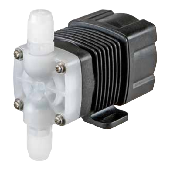
Iwaki Hi-Resolution Pump
HRP (Standard)
Instruction manual
Thank you for choosing our product.
Please read through this instruction manual before use.
This instruction manual describes important precautions and
instructions for the product. Always keep it on hand for quick
reference.
© 2008 IWAKI CO.,LTD.
Advertisement
Table of Contents

Related Manuals for IWAKI PUMPS HRP-54V


Summary of Contents for IWAKI PUMPS HRP-54V
- Page 1 Iwaki Hi-Resolution Pump HRP (Standard) Instruction manual Thank you for choosing our product. Please read through this instruction manual before use. This instruction manual describes important precautions and instructions for the product. Always keep it on hand for quick reference. ©...
-
Page 2: Order Confirmation
Order confirmation After unpacking, check the following points. Contact us or your nearest dealer if the delivery is imperfect. a. Check if the delivery is as per order. Check the nameplate to see if the dis- charge capacity, discharge pressure and voltage are as per order. -
Page 3: Table Of Contents
Contents Order confirmation ..................... 2 Safety instructions ............... 5 WARNING ......................6 CAUTION ......................7 Precautions for use ..................9 Outline ..................11 Introduction .....................11 Pump structure & Operating principle ............11 Features .......................12 Operational function ..................12 Part names.......................13 Identification codes ..................14 Installation .................. - Page 4 Pump & Drive units ................43 Control unit .................... 43 Power cable ................... 43 Option ......................44 Check valve with an air vent ..............44 Check valve ................... 44 Outer dimension ..................45 HRP-54V ....................45 HRP-54H ....................45 Contents...
-
Page 5: Safety Instructions
Safety instructions Read through this section before use. This section describes important information for you to prevent personal injury or property damage. ■ Pictorial indication In this instruction manual, the estimated risk of degree caused by incorrect use is ranked with the following pictorial indications. First, fully understand informa- tion on the pictorial indications. -
Page 6: Warning
WARNING Turn off power before work Risk of electrical shock. Be sure to turn off power to stop the pump and related devices before work. Electrical shock Stop the operation On sensing any abnormality or dangerous sign, suspend operation immediately and inspect/solve problems. Requirement Do not use the pump in anything other than a specified purpose The use of the pump in any purpose other than those clearly speci-... -
Page 7: Caution
CAUTION A qualified operator only The pump must be handled or operated by a qualified person with a full understanding of the pump. Any person who is not familiar with Requirement this product should not take part in operation or management. Use a specified power only Do not apply any power other than the one specified on the nameplate. - Page 8 Observe the correct polarity Otherwise the pump may fail. Caution Do not use the pump in a water place The pump is not totally waterproof. The use of the pump in water or high humidity could lead to electrical shock or short circuit. Prohibition Wear part replacement Follow instructions in this manual for wear part replacement.
-
Page 9: Precautions For Use
Precautions for use • Electrical work should be performed by a qualified opera- tor. Otherwise, personal or property damage accident may result. Caution • Do not install the pump in the following places where... –Under a flammable atmosphere or in a dusty/humid place. –Under direct sunlight or wind &... - Page 10 • Be careful not to drop the pump onto the floor. A strong impact may reduce pump performance. Do not use a pump which has once damaged. Otherwise an electrical leak or shock may result. • The pump is a light water-/dust-proof structure of IP65, but is not totally waterproof.
-
Page 11: Outline
Outline The information such as characteristics, features and part names are described in this section. Introduction Pump structure & Operating principle The HRP series is a diaphragm metering pump which consists of a pump head, drive unit and control unit. A diaphragm is directly driven by electromag- netic force. -
Page 12: Features
Features 12/24VDC power voltage The HRP series powered by 12VDC or 24VDC offers the best fit to the built-in application. High resolution Digitally-controlled spm range is 0-720spm. The minimum flow of 0.055ml per shot offers a constant imperceptible injection. * The operation speed of the stop control type is always fixed to 720spm and is not vari- able. -
Page 13: Part Names
Part names Control unit Drive unit Outlet Pump head unit H type (Pump head) V type Inlet Nameplate Describes the pump specification. Power cable terminal Base Always fix with screws. Part names... -
Page 14: Identification Codes
Identification codes The model code represents the following information. HRP - 5 4 V - 1 P 1 - b c d e f g a. Series name HRP: High resolution pulse pump b. Drive unit (Average power consumption) 5: 5.6W c. -
Page 15: Installation
Installation This section describes the installation of the pump, tubing and wiring. Read through this section before work. Observe the following points when installing the pump. • Be sure to turn off power to stop the pump and related devices before work. •... -
Page 16: Pipework
Pipework Connect tubes to the pump and install a check valve. Before operation Tube end (Side view) • Select proper chemical resistant tubes. • The tubes should resist liquid temperature and pressure. • Cut the tube ends flat. Tube connection Pass a tube into the fitting nut and slide down Tube the tube onto the fitting. -
Page 17: Check Valve Mounting
NOTE Air vent valve mounting • Install valves on both suction and discharge Check valve lines for the convenience of maintenance. Discharge line • Install a three-way joint on the discharge line Three way joint close to the pump to lay on an air vent line. Air vent Maintenance valve... - Page 18 • Suction line pressure is higher than discharge line pressure. In this state siphon or overfeeding happens. Mount the optional check valve at the discharge tube end. * The CA check valve has R1/2 and R3/8 thread connections as well as tube connection.
-
Page 19: Avc Check Valve With An Air Vent (Option)
AVC check valve with an air vent (Option) AVC check valve is designed for being used with the HRP and works for both back-flow check and bleeding. ■ Specification Model Set pressure Tube connection bore AVC-FC1 ø3×ø6mm AVC-FC2 0.1MPa ø4×ø6mm AVC-FC3 1/8"×1/4"... -
Page 20: Wiring
Wiring Wiring for the power source, earthing and external signal. Observe the following points during wiring work. • Electrical work should be performed by a qualified operator. Always ob- serve applicable codes or regulations. • Observe the rated voltage. Otherwise the electrical circuit on the control unit may break. - Page 21 Remove the attached triplex cable from the control unit. Unfasten a snap-fit connector and pull out the cable. Unfasten a snap Connect power and external signal wires. Observe the correct polarity. Allocate pink and black wires for the power, and white and black wires for the external signal.
- Page 22 4-20mA control type or 1-5V control type Note that white wire is positive and black wire is negative. 4-20mA control type 1-5V control type Pink White Black Pink White Black +12VDC or +12VDC or 1-5VDC 4-20mADC +24VDC +24VDC External device External device NOTE •...
- Page 23 NOTE • Power voltage should be charged at a sitting via a switch or a relay. Otherwise CPU may malfunction. See below for the precautions for ON-OFF control by the relay. When the power is applied at a sitting When the power is applied gradually POWER POWER TIME...
-
Page 24: Operation
Operation The pump becomes ready after pipework and wiring is com- pleted. This section describes pump operation and programming. Before operation Check the liquid level in the supply tank, tubing and wiring. And then perform degassing and flow rate adjustment before starting operation. Points to be checked Before operation, check if... -
Page 25: Degassing
Use of a Phillips screwdriver instead of a torque driver (a) Lightly tighten the pump head unit fixing screws until the sprig washer be- comes flat. (b) Further turn the screws clockwise 180 degrees. 180° Until spring washer becomes flat Degassing The gas needs to be expelled from the pump and tubing by degassing. - Page 26 Install an air vent valve or AVC check valve on piping for degassing. Follow the procedure below to conduct degassing in case neither valve is available. Connect a discharge tube and place the tube end in the supply tank or Outlet another container.
-
Page 27: Operation
Operation This pump is controlled by the external signal. Read through this section for proper operation. ■ Operation of the Pulse control type The input of the pulse signal controls the pump operation (stroke rate). The pump makes one shot per pulse synchronously. *The signal input is required to make operation after power activation for this type. -
Page 28: Operation Of The 1-5V Control Type
■ Operation of the 1-5V control type The input of 1-5VDC proportionally controls the pump operation (stroke rate). A stroke rate decreases to 0spm at 1VDC and increases to 720spm at 5VDC. *The signal input is required to make operation after power activation for this type. *An input voltage should be in between 1 to 5VDC and should not exceed the range. -
Page 29: Flow Rate Adjustment
Flow rate adjustment The flow rate is adjusted by the stroke rate. The stroke rate is indicated in spm (stroke per minutes). A stroke rate is determined by the number of external signals. Determine a suitable stroke rate, taking account of the pump operating condi- tion and liquid characteristics. -
Page 30: Maintenance
Maintenance This section describes troubleshooting, inspection, wear part replacement, exploded views and specifications. Important • Observe instructions in this manual for maintenance, inspection, disman- tlement and assembly. Do not dismantle the pump beyond the extent of the instructions. • Always wear protective clothing such as an eye protection, chemical resistant gloves, a mask and a work cap during dismantlement, assembly or maintenance work. -
Page 31: Inspection
Liquid can Foreign matters are stuck in the • Dismantle, inspect and clean not be pump head valves. the pump head unit. Replace as sucked up. necessary. A ball valve is stuck on a valve seat. The flow Air stays in the pump head. •... -
Page 32: Periodic Inspection
Periodic inspection Retighten the pump head unit fixing screws diagonally every three months ac- cording to the following torque. * Mounting screws may loosen in operation. How fast the screws start to loosen is de- pending on operating conditions. Tightening torque Torque Screw 0.7 N•m... -
Page 33: Wear Part Replacement
Wear part replacement For a long operation wear parts need to be replaced periodically. It is recommended that the following parts are always stocked for immediate replacement. Contact us or your nearest dealer for detail. Precautions • When dismantling the pump, pay attention to the residual liquid in the pump. -
Page 34: Before Replacement
Before replacement First release the pressure from the pump and discharge line. Otherwise, liquid may gush out. Stop the pump operation. Release the internal pressure. Open the air vent valve if it is installed. If not, see page 25. Check that liquid comes out from the air vent port and the internal pressure has been expelled. - Page 35 Turn the diaphragm anticlockwise to detach it from the plunger. NOTE Pay attention not to lose diaphragm spacers. Always apply a proper number of dia- phragm spacers. 0 or a few diaphragm spacers are inserted between the retainer and plunger for the adjustment of diaphragm location. Note that the number of diaphragm spacers varies with pump model.
- Page 36 Turn the diaphragm clockwise to attach it to the plunger. Place the O ring into the O ring groove on the pump head unit. * Make sure the O ring does not stick out from the groove. O ring Pump head unit * When O ring can not fit in...
-
Page 37: Maintenance (Avc Check Valve)
Maintenance (AVC check valve) Precautions • When dismantling the check valve, pay attention to the residual liquid in the pump. • Rinse wet ends thoroughly with water. Exploded view (AVC check valve) Part names Q'ty Body Fitting nut Fitting Air vent valve Stopper screw Poppet valve Spring... -
Page 38: Wear Parts List (Avc Check Valve)
Wear part list (AVC check valve) # of Estimat- Parts parts ed life Poppet valve with O rings 8000 Spring hours Orings * Wear part duration varies with the pressure, temperature and characteristics of the liquid. * The estimated life is calculated based on the continuous operation with ambient clean water. * Replace the poppet valve, spring and O rings at the same time. - Page 39 Dismantlement Detach the AVC check valve. Loosen the fitting nut and remove tubes from the IN, OUT and AIROUT ports. Remove the fitting nut. Use an adjustable wrench or spanner to Fitting unscrew the fitting nut. Take out a spring, poppet valve and O rings. Use a pair of tweezers as necessary.
- Page 40 Unscrew the stopper from the changeo- Stopper screw ver knob. Unscrew the changeover knob. Stopper screw Detach O rings. O ring O ring Attach new O rings. Maintenance (AVC check valve)
- Page 41 Screw in the changeover knob until it bottoms out. Do not tighten the knob too much so that the changeover knob stops at a rotation limit. Changeover knob Rotation limit Stopper Screw the stopper screw in the knob. Use a precision screw driver. NOTE Do not tighten the stopper screw too much.
-
Page 42: Exploded View
Exploded view Pump head, Drive unit & Control unit Observe instructions in this manual to dismantle the pump. Drive unit + Control unit Power cable Diaphragm spacer Pump head unit (V type) O ring Plunger (Pump shaft) Diaphragm Fitting Fitting nut Pump head unit (H type) Fitting Fitting nut... -
Page 43: Specification/Outer Dimension
Current Power Model code Flow rate discharge consump- Weight rate tion bore value voltage pressure tion ø3×ø6mm HRP-54V/H-1 12VDC 1.5A 0.2MPa 0-720spm ø4×ø6mm 5.6W 0.5kg mℓ/min HRP-54V/H-2 24VDC 1.0A ø1/8"×ø1/4" * This specification is based on pumping clean water at ambient temperature and rated voltage. -
Page 44: Check Valve With An Air Vent
Option ■ Check valve with an air vent Materials Model code Set pressure Tube connection bore O ring Spring Body AVC-FC1 ø3×ø6mm AVC-FC2 0.1MPa ø4×ø6mm PVDF HC276 AVC-FC3 ø1/8"×ø1/4" ■ Check valve Tube connection bore Materials Model code Set pressure O ring Spring Body... -
Page 45: Outer Dimension
Outer dimensions ■ HRP-54V (101) (25) 22.5 ■ HRP-54H (122) (56) 22.5 Outer dimensions... - Page 46 TEL : (47)66 81 16 60 FAX : 66 81 16 61 China IWAKI Pumps (Guandong) Co., Ltd. TEL : (86)750 3866228 FAX : 750 3866278 Singapore IWAKI Singapore Pte. Ltd. TEL : (65)6316 2028 FAX : 6316 3221 China GFTZ IWAKI Engineering &...
Need help?
Do you have a question about the HRP-54V and is the answer not in the manual?
Questions and answers