
Related Manuals for IWAKI PUMPS FS-80NT Series


Summary of Contents for IWAKI PUMPS FS-80NT Series
- Page 1 IWAKI Pneumatic Drive Bellows Pump FS-80NT Instruction Manual Read this manual before use of product...
-
Page 2: Table Of Contents
Thank you for having selected IWAKI's Pneumatic Drive Bellows Pump FS-80NT Series. This instruction manual, which is divided into 5 sections, namely “Safety Section,” “Outline Section,” “Installation Section,” “Operation Section” and “Maintenance Section,” deals with the correct handling and operation procedures for the pump. To make maximum use of the pump and to ensure safe and long operation of the pump, please read this manual thoroughly and carefully prior to operating the pump. -
Page 3: Before Use Of The Fs-80Nt Series Pumps
● Use of the FDC-1 controller is recommended, however, the AC-1, FD, SC controllers are not usable to the FS-80NT series pumps. The electropneu- matic regulator is not applicable, either. ● The maximum stroke speed is limited at each supply air range. See the table below. -
Page 4: Important Instructions
Important Instruction For the Safe and Correct Handling of the Pump • Read the "Safety Instructions" sections carefully to prevent accidents involving your customers or other personnel and to avoid damage or loss of other assets. Always follow the instructions and advice found in these sections. -
Page 5: Safety Section (Instructions To Prevent Accidents)
Safety section WARNING • Look around Make sure there is no one around the pump when connecting the power cable. Any power supply switch is not provided on the pump. Connecting the power cable sup- plies air to the pump and pump starts operation. •... - Page 6 Safety section CAUTION • Power OFF Make sure no one turns on the power switch while working on the pump. Be sure to turn off the power switch before starting any maintenance/repair work concern- ing the pump. If the working site is noisy or dark, display a notice which clearly states "POWER OFF(Maintenance),"...
- Page 7 Safety section CAUTION • Liquids to be handled with care · Stripper · Solvent-type liquid · Fuming sulfuric acid · Fuming nitric acid • Static electricity When low electric conductivity liquids such as ultra-pure water and fluor inactive liquid (e.g. Fluorinert ) are handled, the static electricity may generate in the pump, which may cause static discharge and damage pump.
-
Page 8: Outline Of Product
OUTLINE OF PRODUCT This section deals with operating principle, type and specifications of the pump as an introduction of the pneumatic drive bellows pump. 1. Unpacking and Inspection ....6 2. Operating Principle ......6 3. Identification Codes ......7 4. -
Page 9: Unpacking And Inspection
1. Unpacking and Inspection After unpacking the product, check the following points to ascertain that the product is exactly as you ordered. If you find anything wrong, please contact your dealer. [1] Does the model indicated on the nameplate repre- sent what you ordered? [2] Has the pump or any part of it been damaged as the result of an accident or mishandling in transit? -
Page 10: Identification Codes
3. Identification Codes FS - 80 N T - 01 (2) (3) (4) (1) Series code (2) Maximum discharge volume 80: 80 L/min. (3) Operating temperature N: 5 - 60 deg.C (4) Pump connection port (discharge port/suction port) T: Tube type connection (Standard) (5) Special specifications No symbol : Standard : Special specifications (01, 02······) -
Page 11: Outer Dimensions/Mass
5. Outer Dimensions/Mass FS-80NT Mass : 23.5kg Unit : mm - 8 - - 8 -... -
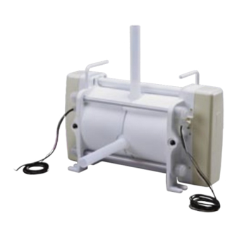
Page 12: Names Of Parts And Structure Of Pump
6. Names of Parts and Structure of Pump FS-80NT Parts Name Q'ty Material Remarks Parts Name Q'ty Material Remarks 37 Nominal dia. 1 Pump head 1 PTFE 29 Stop ring 2 Stainless steel 2 Tube 2 PFA 30 Screw 8 Stainless steel M3×8 Precoat 3 Bellows 2 PTFE... -
Page 13: Description On Body And Label
7. Description of Body and Label Caution When cleaning the pump be careful not to wipe the labels or the pump body with solvent. Discharge port Handle OUT label Caution label IN label Suction port Air port Name plate Cord Cord for the proximity switch and the electrode. -
Page 14: Installation Section
INSTALLATION SECTION This “Installation Section“ must be thoroughly understood by the user before actually installing the pump. Do not start your installation work unless con- firming your understanding of the entire set of descriptions in this section. 1. Before Use ........12 2. -
Page 15: Before Use
1. Before Use Safety measures should be taken correctly for the pump unit and the entire system. Observe operating cautions and the measures to ensure the safe operation of the system, reading the following description carefully. To operate this pump, the 3-position 5 port solenoid valve and the FDC-1 type controller are required. In addition, to enhance system safety, a quick exhaust valve must be installed. - Page 16 Points to be Observed Description Do not suspend pump operation for Caution a long period with any liquid in the Suspending pump operation for a long period with any liquid pump. in the pump chamber may cause corrosion of the electrode or other parts due to permeation of the liquid’s gas content.
-
Page 17: Installation, Piping, And Wiring
2. Installation, Piping, and Wiring When perceiving any danger or abnormal condition during installation or set-up work, stop the work. WARNING Make sure power switch is turned off before installation or piping/wiring arrangement and is not turned on unintentionally. If the working site is noisy or dark, display a notice which clearly states “POWER OFF(MAINTENANCE),”... -
Page 18: Liquid Tubing
2.2 Liquid Tubing The standard tubes for both discharge and suction ports are PFA . Connect the tubes as described below [1] Pump port diameters and materials Attached to tube To piping line from pump head The standard tube of discharge/suction port is PFA. The applicable tubing diameters are as follows. - Page 19 2.2.2 Points to be observed in discharge pipe arrangement [1] A pump discharge load increases as discharge pipe length is longer or pipe has many bends on it. In order to decrease a load, install a dampener which minimizes pulsation. Install a check valve on discharge pipe in riser pip- ing.
-
Page 20: Air Piping
2.3 Air Piping CAUTION Instrument air which is clean and free from moisture and dust should be used as supply air. If water, oil, or dust enter the supplied air, the pump may fail in starting. If water enter the air chambers, the electrode may detect it and sounds an alarm. - Page 21 [3] Electromagnetic valve Use table below to select your 5 port solenoid valve. Model Necessary effective cross-sectional area Diameter of port FS-80NT 85mm or larger Rc 3/8" or larger Caution Use the 3-position 5 port exhaust center type solenoid valve. [4] Muffler A muffler is installed on the exhaust port of the solenoid valve and quick exhaust valve.
- Page 22 [6] Quick exhaust valve As shown in Figure 1, the air exhausted out of the pump flows out of the system via the exhaust port of the electro- magnetic valve. (Fig. 1) Depending upon the type of liquid applied, some permeated gas may mix with the exhaust air. (The inside of the electromagnetic valve may be corroded by such permeated gas, becoming useless to the system.) In such a case, install a quick exhaust valve between the pump and the electromagnetic valve.
- Page 23 2.3.2 Points to be observed in air piping [1] Diameter of pump connection port The diameter of the connection port on the air sup- ply side is as follows. Pump air supply * Connection port diameter port (pump) FS-80NT: Rc 3/8" Piping side tube Tube coupling [2] Install a relief type reducing valve.
-
Page 24: Wiring
2.3.3 Effective cross-sectional area [1] Effective cross-sectional area In the field of pneumatic devices, the term “Effective cross-sectional area” is used to indicate the capacity to allow air to flow freely. When air is sent through a pipe, the air cannot run totally through the actual cross-sectional area of the pipe due to the negative effect of the piping resistance. - Page 25 2.4.1 Wiring with the AC-1 controller The following diaphragm shows the connection diagram of the FS-80NT and the FDC-1 controller. Refer to instruc- tion manual for further information. - 22 -...
- Page 26 [1] Wiring for proximity switch Caution The proximity switches of the FS-80NT has three wires: black, white, and red. Improper wiring may cause the proximity switch burn. Carry out the wiring carefully and accurately. ► Connect the wires (black, white, and red) of proximity switch R with terminals CN3 of the controller. ►...
- Page 27 2.4.3 Wiring instructions [1] Extension of electrode wire Control the resistance value to 5k Ω or lower, including the attached lead wire (about 1.8m in length). Any resistance larger than 5k Ω may result in inability to stop the pump. (Because detection by the auto-stop alarm will not be available due to the valve in excess of the detection range of the controller when the bellows is damaged.) [2] Wiring of proximity switch...
-
Page 28: Operation Section
OPERATION SECTION Pump operation shall be limited to the range covered by and described in this instruction manual. Use of the pump in a different method or procedure that is not described in this instruction manual is prohibited. Iwaki takes no responsibility for injury to person or damage to assets which results from a failure to observe this instruction. -
Page 29: Preparation
1. Preparation Carry out the following preparatory steps when starting the pump operation for the first time after installation or after a long-time suspension of the pump operation. [1] Confirm that the electric wiring has been conducted correctly. (Wiring for proximity switch and electromagnetic valve.) Caution Improper wiring may cause burned proximity switch. -
Page 30: Points To Be Observed In Operation
2.2 Stopping pump [1] Operate the FDC-1 controller to stop the pump. Refer to the FDC-1 instruction manual for detail. [2] Make sure the discharge-side valve is open when stopping the pump. Caution Do not close the discharge-side valve right after stopping the pump. [3] Make sure the system does not allow residual pressure on the discharge side at pump stopping. -
Page 31: Maintenance Section
MAINTENANCE SECTION Handling, maintenance and inspection of the pump shall be limited to the range covered by and described in this instruction manual. Handling of the pump beyond the range covered by this instruction manual is prohibited. Iwaki takes no responsi- bility for injury to person or damage to assets caused from a failure to observe this instruction. -
Page 32: Causes Of Trouble And Troubleshooting
1. Causes of Trouble and Troubleshooting Trouble Causes Countermeasures Inspection and check points Faulty selection of solenoid Inspect and repair or a Use a quick exhaust valve if corrosive valve. gas influences. replace. Improper wiring or discon- Inspect and correct a Check if the three wires are arranged nection in proximity switch wiring. - Page 33 Trouble Causes Countermeasures Inspection and check points Supply air pressure or air vol- Set back to initial set a Secure a diameter and air flow rate in ume is reduced. consideration of the number of pumps value or review air installed.
-
Page 34: Maintenance And Inspection
2. Maintenance and Inspection WARNING ● Wear protectors Make sure to wear protective gear (protective goggles, cap, mask, etc.) when carrying out maintenance and inspection work. ● Release pressure out of piping Residual pressure in the piping may force the liquid and cause an unexpected accident. Release the residual pressure before starting the work. - Page 35 TEL : (1)508 429 1440 FAX : 508 429 1386 Germany : IWAKI EUROPE GmbH TEL : (49)2154 9254 0 FAX : 2154 1028 Australia : IWAKI Pumps Australia Pty. Ltd. TEL : (61)2 9899 2411 FAX : 2 9899 2421 Italy : IWAKI Italia S.R.L.
Need help?
Do you have a question about the FS-80NT Series and is the answer not in the manual?
Questions and answers